Table of Contents
Advertisement
44158 ANCENIS CEDEX - FRANCE
MSI 20 T Série 2-E3 - MSI 20 T BUGGIE Série 2-E3
MSI 25 T Série 2-E3 - MSI 25 T BUGGIE Série 2-E3
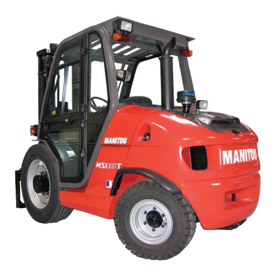
MSI 30 T Série 2-E3 - MSI 30 T BUGGIE Série 2-E3
MSI 35 T Série 2-E3 - MSI 35 T BUGGIE Série 2-E3
THIS OPERATOR'S MANUAL MUST BE KEPT IN THE LIFT TRUCK AND MUST BE READ AND UNDERSTOOD BY OPERATORS.
MANITOU BF
BP 10249
TEL: + 33 (0)2 40 09 10 11
YOUR DEALER
647000 EN (03/05/2010)
MH 20-4 T BUGGIE Série 2-E3
MH 25-4 T BUGGIE Série 2-E3
OPERATOR'S MANUAL
Advertisement
Table of Contents

Related Manuals for Manitou MSI 30 T


Summary of Contents for Manitou MSI 30 T
- Page 1 MSI 20 T Série 2-E3 - MSI 20 T BUGGIE Série 2-E3 MSI 25 T Série 2-E3 - MSI 25 T BUGGIE Série 2-E3 MSI 30 T Série 2-E3 - MSI 30 T BUGGIE Série 2-E3 MSI 35 T Série 2-E3 - MSI 35 T BUGGIE Série 2-E3 MH 20-4 T BUGGIE Série 2-E3...
- Page 3 1 - OPERATING AND SAFETY INSTRUCTIONS 2 - DESCRIPTION 3 - MAINTENANCE 4 - ADAPTABLE ATTACHMENTS IN OPTION ON THE RANGE 02/07/2008 1st DATE OF ISSUE 23/03/2009 UP DATING (2-4; 2-7; 2-9; 2-11; 2-13 – 2-17; 2-22 – 2-29; 3-6 – 3-9) 03/05/2010 UP DATING (1-5 ;...
- Page 5 1 - OPERATING AND SAFETY INSTRUCTIONS...
-
Page 7: Table Of Contents
TABLE OF CONTENTS INSTRUCTIONS TO THE COMPANY MANAGER 1 - 4 THE SITE 1 - 4 THE OPERATOR 1 - 4 THE LIFT TRUCK 1 - 4 A - THE LIFT TRUCK’S SUITABILITY FOR THE JOB 1 - 4 B - ADAPTATION OF THE LIFT TRUCK TO STANDARD ENVIRONMENTAL CONDITIONS 1 - 4 C - MODIFICATION OF THE LIFT TRUCK 1 - 5... -
Page 8: Instructions To The Company Manager
A - THE LIFT TRUCK’S SUITABILITY FOR THE JOB - MANITOU has ensured that this lift truck is suitable for use under the standard operating conditions defined in this operator’s manual, with a STATIC TEST COEFFICIENT OF 1.33 and a DYNAMIC TEST COEFFICIENT OF 1, as specified in harmonised norm EN 1726-1 for mast trucks. -
Page 9: C - Modification Of The Lift Truck
C - MODIFICATION OF THE LIFT TRUCK - For your safety and that of others, you must not change the structure and settings of the various components used in your lift truck (hydraulic pressure, calibrating limiters, I.C. engine speed, addition of extra equipment, addition of counterweight, unapproved attachments, alarm systems, etc.) yourself. -
Page 10: Instructions For The Operator
INSTRUCTIONS FOR THE OPERATOR PREAMBULE WHENEVER YOU SEE THIS SYMBOL IT MEANS: WARNING ! BE CAREFUL ! YOUR SAFETY OR THE SAFETY OF THE LIFT TRUCK IS AT RISK. The risk of accident while using, servicing or repairing your lift truck can be restricted if you follow the safety instructions and safety measures detailed in these instruction. -
Page 12: Operating Instructions Unladen And Laden
OPERATING INSTRUCTIONS UNLADEN AND LADEN A - BEFORE STARTING THE LIFT TRUCK - Carry out daily maintenance (see: 3 - MAINTENANCE: A - DAILY OR EVERY 10 HOURS SERVICE). - Make sure the lights, indicators and windscreen wipers are working properly. - Make sure the rear view mirrors are in good condition, clean and properly adjusted. -
Page 13: C - Environment
C - ENVIRONMENT - Comply with site safety regulations. - If you have to use the lift truck in a dark area or at night, make sure it is equipped with working lights. - During handling operations, make sure that no one is in the way of the lift truck and its load. - Do not allow anybody to come near the working area of the lift truck or pass beneath an elevated load. -
Page 14: E - Starting The Lift Truck
E - STARTING THE LIFT TRUCK SAFETY NOTICE The lift truck must only be started up or manoeuvred when the operator is sitting in the driver’s cab, with his seat belt adjusted and fastened. - Never try to start the lift truck by pushing or towing it. Such operation may cause severe damage to the transmission. If necessary, to tow the lift truck in an emergency, the transmission must be placed in the neutral position (see: 3 - MAINTENANCE: G - OCCASIONAL MAINTENANCE). -
Page 15: G - Stopping The Lift Truck
- Use the rear-view mirrors frequently. - Drive round obstacles. - Never drive on the edge of a ditch or steep slope. - It is dangerous to use two lift trucks simultaneously to handle heavy or voluminous loads, since this operation requires particular precautions to be taken. -
Page 16: H - Driving The Lift Truck On The Public Highway
H - DRIVING THE LIFT TRUCK ON THE PUBLIC HIGHWAY SAFETY INSTRUCTIONS - Operators driving on the public highway must comply with current highway code legislation. - The lift truck must comply with current road legislation. If necessary, there are optional solutions. Contact your dealer. INSTRUCTIONS - Make sure the revolving light is in place, switch it on and verify its operation. -
Page 17: Instructions For Handling A Load
A - CHOICE OF ATTACHMENTS - Only attachments approved by MANITOU can be used on its lift trucks. - Make sure the attachment is appropriate for the work to be done (see: 4 - ADAPTABLE ATTACHMENTS IN OPTION ON THE RANGE). -
Page 18: C - Transverse Attitude Of The Lift Truck
C - TRANSVERSE ATTITUDE OF THE LIFT TRUCK The transverse attitude is the transverse slope of the chassis with respect to the horizontal. Raising the load reduces the lift truck’s lateral stability. The transverse attitude must be set with the mast in down position as follows: - Position the lift truck so that the bubble in the level is between the two lines (see: 2 - DESCRIPTION: INSTRUMENTS AND CONTROLS). -
Page 19: E - Taking Up And Laying A High Load On Tyres
E - TAKING UP AND LAYING A HIGH LOAD ON TYRES You must not raise the mast if you have not checked the transverse attitude of the lift truck (see: INSTRUCTIONS FOR HANDLING A LOAD: C - TRANSVERSE ATTITUDE OF THE LIFT TRUCK). REMINDER: Make sure that the following operations can be performed with good visibility (see: OPERATIONS INSTRUCTIONS UNLADEN AND LADEN: D - VISIBILITY). -
Page 20: Maintenance Instructions Of The Lift Truck
MAINTENANCE INSTRUCTIONS OF THE LIFT TRUCK GENERAL INSTRUCTIONS - Ensure the area is sufficiently ventilated before starting the lift truck. - Wear clothes suitable for the maintenance of the lift truck, avoid wearing jewellery and loose clothes. Tie and protect your hair, if necessary. -
Page 21: Welding
WELDING - Disconnect the battery before any welding operations on the lift truck. - When carrying out electric welding work on the lift truck, connect the negative cable from the equipment directly to the part being welded, so as to avoid high tension current passing through the alternator. - Never carry out welding or work which gives off heat on an assembled tyre. -
Page 22: Introduction
The following recommendations are intended to prevent the lift truck from being damaged when it is withdrawn from service for an extended period. For these operations, we recommend the use of a MANITOU protective product, reference 603726. Instructions for using the product are given on the packaging. -
Page 23: Bringing The Lift Truck Back Into Service
BRINGING THE LIFT TRUCK BACK INTO SERVICE - Remove the waterproof adhesive tape from all the holes. - Refit the intake hose. - Refit and reconnect the battery. - Remove the protection from the cylinder rods. - Perform the daily service (see: 3 - MAINTENANCE: A - DAILY OR EVERY 10 HOURS SERVICE). - Put the handbrake on and remove the axle stands. - Page 24 1-20...
- Page 25 2 - DESCRIPTION...
- Page 27 CHARACTERISTICS MSI 25 T Série 2-E3 MSI 25 T BUGGIE Série 2-E3 2-10 CHARACTERISTICS MSI 30 T Série 2-E3 MSI 30 T BUGGIE Série 2-E3 2-12 CHARACTERISTICS MSI 35 T Série 2-E3 MSI 35 T BUGGIE Série 2-E3 2-14 CHARACTERISTICS MH 20-4 T BUGGIE Série 2-E3...
- Page 28 430, rue de l’Aubinière - BP 10249 - 44158 - ANCENIS CEDEX - FRANCE Address Dossier technique, MANITOU BF - 430, rue de l’Aubinière Technical file BP 10249 - 44158 - ANCENIS CEDEX - FRANCE Constructeur de la machine décrite ci-après, Manufacturer of the machine described below MSI 20 T Série 2-E3...
- Page 29 bg : 1) cs : 1) da : 1) de : 1) el : 1) es : 1) et : 1) fi : 1) ga : 1) hu : 1) is : 1) it : 1) lt : 1) lv : 1) mt : 1) nl : 1) no : 1)
- Page 30 NOTE: For the owner’s convenience, it is recommended that a note of these numbers is made in the spaces provided, at the time of the delivery of the lift truck. LIFT TRUCK MANUFACTURER’S PLATE (FIG. A) - Model - Series MANITOU BF 44158 ANCENIS CEDEX FRANCE MODELE MODELLO SERIE SERIE...
- Page 31 - Year of manufacture MAST (FIG. I) - Mast identification Nr ATTACHMENT MANUFACTURER’S PLATE (FIG. J) - Model - Serial Nr - Year of manufacture MANITOU BF 44158 ANCENIS CEDEX FRANCE MODELE N dans la série Année fabrication Masse à vide...
- Page 32 CHARACTERISTICS MSI 20 T Série 2-E3 MSI 20 T BUGGIE Série 2-E3 I.C. ENGINE Type KUBOTA V2403 M T E3 1J477-23000 Fuel Diesel Number of cylinders 4 in line Suction Supercharged Injection system Mechanical Ignition sequence 1-3-4-2 Capacity 2434 Bore and stroke 87 x 102,4 Compression ratio 23/1...
- Page 33 HYDRAULIC CIRCUIT Hydraulic pump CASAPPA Type Gear pump Capacity Max. rating capacity unladen l/mn Flow rate at 1800 rpm l/mn Filtration Return µm Suction µm Maximum service pressure Double mast with all-round vision Triple mast with free-acting lift Double mast with free-acting lift Triple mast without free-acting lift Front/rear tilting circuit 140/140...
- Page 34 CHARACTERISTICS MSI 25 T Série 2-E3 MSI 25 T BUGGIE Série 2-E3 I.C. ENGINE Type KUBOTA V2403 M T E3 1J477-23000 Fuel Diesel Number of cylinders 4 in line Suction Supercharged Injection system Mechanical Ignition sequence 1-3-4-2 Capacity 2434 Bore and stroke 87 x 102,4 Compression ratio 23/1...
- Page 35 HYDRAULIC CIRCUIT Hydraulic pump CASAPPA Type Gear pump Capacity Max. rating capacity unladen l/mn Flow rate at 1800 rpm l/mn Filtration Return µm Suction µm Maximum service pressure Double mast with all-round vision Triple mast with free-acting lift Double mast with free-acting lift Triple mast without free-acting lift Front/rear tilting circuit 170/170...
- Page 36 CHARACTERISTICS MSI 30 T Série 2-E3 MSI 30 T BUGGIE Série 2-E3 I.C. ENGINE Type KUBOTA V2403 M T E3 1J477-23000 Fuel Diesel Number of cylinders 4 in line Suction Supercharged Injection system Mechanical Ignition sequence 1-3-4-2 Capacity 2434 Bore and stroke...
- Page 37 HYDRAULIC CIRCUIT Hydraulic pump CASAPPA Type Gear pump Capacity Max. rating capacity unladen l/mn Flow rate at 1800 rpm l/mn Filtration Return µm Suction µm Maximum service pressure Double mast with all-round vision Triple mast with free-acting lift Double mast with free-acting lift Triple mast without free-acting lift Front/rear tilting circuit 185/185...
- Page 38 CHARACTERISTICS MSI 35 T Série 2-E3 MSI 35 T BUGGIE Série 2-E3 I.C. ENGINE Type KUBOTA V2403 M T E3 1J477-23000 Fuel Diesel Number of cylinders 4 in line Suction Supercharged Injection system Mechanical Ignition sequence 1-3-4-2 Capacity 2434 Bore and stroke 87 x 102,4 Compression ratio 23/1...
- Page 39 HYDRAULIC CIRCUIT Hydraulic pump CASAPPA Type Gear pump Capacity Max. rating capacity unladen l/mn Flow rate at 1800 rpm l/mn Filtration Return µm Suction µm Maximum service pressure Double mast with all-round vision Triple mast with free-acting lift Double mast with free-acting lift Triple mast without free-acting lift Front/rear tilting circuit 190/190...
- Page 40 CHARACTERISTICS MH 20-4 T BUGGIE Série 2-E3 I.C. ENGINE Type KUBOTA V2403 M T E3 1J477-23000 Fuel Diesel Number of cylinders 4 in line Suction Supercharged Injection system Mechanical Ignition sequence 1-3-4-2 Capacity 2434 Bore and stroke 87 x 102,4 Compression ratio 23/1 Nominal rating loaded...
- Page 41 HYDRAULIC CIRCUIT Hydraulic pump CASAPPA Type Gear pump Capacity Max. rating capacity unladen l/mn Flow rate at 1800 rpm l/mn Filtration Return µm Suction µm Maximum service pressure Double mast with all-round vision Triple mast with free-acting lift Double mast with free-acting lift Triple mast without free-acting lift Front/rear tilting circuit 150/150...
- Page 42 CHARACTERISTICS MH 25-4 T BUGGIE Série 2-E3 I.C. ENGINE Type KUBOTA V2403 M T E3 1J477-23000 Fuel Diesel Number of cylinders 4 in line Suction Supercharged Injection system Mechanical Ignition sequence 1-3-4-2 Capacity 2434 Bore and stroke 87 x 102,4 Compression ratio 23/1 Nominal rating loaded...
- Page 43 HYDRAULIC CIRCUIT Hydraulic pump CASAPPA Type Gear pump Capacity Max. rating capacity unladen l/mn Flow rate at 1800 rpm l/mn Filtration Return µm Suction µm Maximum service pressure Double mast with all-round vision Triple mast with free-acting lift Double mast with free-acting lift Triple mast without free-acting lift Front/rear tilting circuit 180/180...
- Page 44 CHARACTERISTICS OF MASTS WITH ROLLERS MSI 20 T Série 2-E3 MSI 20 T BUGGIE Série 2-E3 MSI 25 T Série 2-E3 MSI 25 T BUGGIE Série 2-E3 DOUBLE MAST WITH ALL-ROUND VISION MAST 3m00 3030 10° 12° 2150 3831 3m30 3330 10°...
- Page 45 CHARACTERISTICS OF MASTS WITH ROLLERS MSI 30 T Série 2-E3 MSI 30 T BUGGIE Série 2-E3 MSI 35 T Série 2-E3 MSI 35 T BUGGIE Série 2-E3 DOUBLE MAST WITH ALL-ROUND VISION MAST 3m00 3035 10° 12° 2150 3893 3m30 3335 10°...
- Page 46 CHARACTERISTICS OF MASTS WITH ROLLERS MH 20-4 T BUGGIE Série 2-E3 MH 25-4 T BUGGIE Série 2-E3 DOUBLE MAST WITH ALL-ROUND VISION MAST 2m70 2730 10° 12° 1995 3531 3m00 3030 10° 12° 2145 3831 3m30 3330 10° 12° 2295 4131 3m50 3530 10°...
- Page 47 2-23...
- Page 48 FRONT AND REAR TIRES PRESSURE (bar) FRONT TYRE LOAD (kg) PRESSURE 10,5R20 14PR MPT80 134G Front unladen TUBELESS Front laden 2450 2850 3400 3700 2550 2900 CONTINENTAL PRESSURE Plein Plein Plein Plein 8,25X20 Front unladen CSE SC15 Front laden 2450 2850 3400 3700...
- Page 49 PRESSURE ON THE CONTACT SURFACE AREA OF THE CONTACT SURFACE PRESSURE LOAD (kg/cm2) (cm2) (bar) (kg) HARD SOIL LOOSE SOIL HARD SOIL LOOSE SOIL 2450 2550 10,5R20 14PR MPT80 134G 2850 TUBELESS 2900 3400 5,40 3700 3,27 3,37 3,56 8,25X20 Plein 2450 6,51...
- Page 50 PRESSURE ON THE CONTACT SURFACE AREA OF THE CONTACT SURFACE PRESSURE LOAD (kg/cm2) (cm2) (bar) (kg) HARD SOIL LOOSE SOIL HARD SOIL LOOSE SOIL 275/70R22,5 GOODYEAR RHS 148/145M 2450 TUBELESS 2850 3400 3700 2450 280/80R20 2550 XMCL TUBELESS 2850 2900 MICHELIN 3,21 1050...
- Page 51 2-27...
- Page 52 DIMENSIONS AND LOAD CHART MSI 20 T Série 2-E3 MSI 20 T BUGGIE Série 2-E3 1100 (mm) 1800 (mm) (mm) 2945 (mm) 4045 (mm) (mm) 1046 1102 (mm) (mm) (mm) (mm) (mm) (mm) (mm) (mm) 2300 (mm) 4131 (mm) (mm) 1025 (mm) CAPACITE NOMINALE...
- Page 53 DIMENSIONS AND LOAD CHART MSI 25 T Série 2-E3 MSI 25 T BUGGIE Série 2-E3 1100 (mm) 1800 (mm) (mm) 2945 (mm) 4045 (mm) 1046 (mm) 1102 (mm) (mm) (mm) (mm) (mm) (mm) (mm) (mm) 2300 (mm) 4131 (mm) (mm) 1025 (mm) CAPACITE NOMINALE...
- Page 54 CAPACIDAD EFECTIVA G - G1 - G2 - G3 = Unladen 3000 CAPACITÀ EFFETTIVA 2750 1960 G* - G1* - G2* = Rated load U = MSI 30 T Série 2-E3 218157 U* = MSI 30 T BUGGIE Série 2-E3 2-30...
- Page 55 DIMENSIONS AND LOAD CHART MSI 35 T Série 2-E3 MSI 35 T BUGGIE Série 2-E3 1100 (mm) 1800 (mm) (mm) 3030 (mm) 4130 (mm) 1046 (mm) 1102 (mm) (mm) (mm) (mm) (mm) (mm) (mm) (mm) 2300 (mm) 4193 (mm) (mm) 1025 (mm) CAPACITE NOMINALE...
- Page 56 DIMENSIONS AND LOAD CHART MH 20-4 T BUGGIE Série 2-E3 1100 (mm) 1800 (mm) (mm) 2945 (mm) 4045 (mm) 1160 (mm) 1164 (mm) (mm) (mm) (mm) (mm) (mm) (mm) ROUGH TERRAIN (1) INDUSTRIAL FLOOR (2) (mm) CAPACITE NOMINALE CAPACITE NOMINALE RATED CAPACITY RATED CAPACITY 1835...
- Page 57 DIMENSIONS AND LOAD CHART MH 25-4 T BUGGIE Série 2-E3 1100 (mm) 1800 (mm) (mm) 2945 (mm) 4045 (mm) 1160 (mm) 1164 (mm) (mm) (mm) (mm) (mm) (mm) (mm) ROUGH TERRAIN (1) INDUSTRIAL FLOOR (2) (mm) CAPACITE NOMINALE CAPACITE NOMINALE RATED CAPACITY RATED CAPACITY 1835...
-
Page 58: Instruments And Controls
INSTRUMENTS AND CONTROLS 2-34... - Page 59 DESCRIPTION 1 - DRIVER’S SEAT 2 - SAFETY BELT 3 - CONTROL AND SIGNAL LIGHTS PANEL 4 - SWITCHES 5 - HORN SWITCH 6 - IGNITION SWITCH 7 - BATTERY CUT-OFF 8 - ACCELERATOR PEDAL 9 - SERVICE BRAKE PEDAL AND TRANSMISSION CUT-OFF 10 - FUSES AND RELAYS IN THE CAB 11 - FUSES AND RELAYS UNDER THE CAB (NOT ILLUSTRATED) 12 - FORWARD/NEUTRAL/REVERSE GEAR SELECTION...
- Page 60 1 - DRIVER’S SEAT DESIGNED FOR MAXIMUM COMFORT, THIS SEAT CAN BE ADJUSTED AS FOLLOWS. LONGITUDINAL ADJUSTMENT - Pull the locking lever 1 upwards. - Slide the seat to the required position. - Release the lever and ensure it returns to the lock position. SEAT SUSPÒENSION ADJUSTMENT - Pull and lift up the locking lever 2 so as to place it into one of these five positions.
- Page 61 3 - CONTROL AND SIGNAL LIGHTS PANEL CONTROL INSTRUMENTS A - HOURMETER B - FUEL LEVEL Red zone B1 indicates that you are using the reserve supply and that time of use is limited. 00000 SIGNAL LIGHTS When activating the electrical system of the lift truck, all the red lamps and the panel’s buzzer must light to indicate their good working order.
- Page 62 NOTE: The location of the switches may vary MSI 25 T Série 2-E3 + BUGGIE depending on the options. MSI 30 T Série 2-E3 + BUGGIE MH 20-4 Turbo Série 2-E3 MSI 35 T Série 2-E3 + BUGGIE MH 25-4 Turbo Série 2-E3...
- Page 63 8 - ACCELERATOR PEDAL 9 - SERVICE BRAKE PEDAL AND TRANSMISSION CUT-OFF This pedal operates in two steps: - First, the pedal acts upon a hydraulic valve which progressively cuts off the hydrostatic transmission so as to carry out a slow approach with all the I.C.
- Page 64 12 - FORWARD/NEUTRAL/REVERSE GEAR SELECTION When operating this control, the lift truck should be travelling at slow speed and not accelerating. When the reverser is in the neutral position a mechanical lock prevents an accidental shifting movement. FORWARD: Lift slightly and push the lever forwards (position A). REVERSE: Lift slightly and pull the lever backwards (position B).
- Page 65 17 - LEVEL INDICATOR Enables the operator to check that the lift truck is in the horizontal position. 18 - OVERHEAD GUARD LIFTING Make sure that the mast is tilted forwards to a maximum and the engine is stopped before lifting the overhead guard.
- Page 66 18 - CAB LIFTING (OPTION) Ensure that the mast is tilted forwards to a maximum, that the engine is stopped and that the two doors are shut before lifting the cab. N°234878 UNLOCKING THE CAB - Half-open the right door of the cab. - Keep the ignition on in the lift truck.
- Page 67 19 - ROOF LIGHT (OPTION) 20 - HEATING VENTS (OPTION) 21 - HEATER CONTROL (OPTION) Allows the temperature inside the cab to be adjusted. A - With the valve closed, the fan delivers fresh air. B - With the valve opened completely, the fan delivers warm air. The intermediate positions allow the temperature to be adjusted.
- Page 68 TOWING PIN AND HOOK Located at the rear of the lift truck, this device is used to attach a trailer. Its capacity is limited for each lift truck by the authorised gross vehicle weight, tractive effort and maximum vertical force on the coupling point. This information is given on the manufacturer’s plate fixed to each lift truck (see : 2 - DESCRIPTION : IDENTIFICATION OF THE LIFT TRUCK).
- Page 69 2-45...
- Page 70 DESCRIPTION AND USE OF ELECTRIC AND HYDRAULIC OPTIONS 1 - REVOLVING LIGHT The revolving light is dismountable to make it possible, for example, to reduce the bulkiness of the lift truck or to avoid being stolen. - Loosen nut 1 and remove the revolving light. - Protect mounting 2 with cap 3.
- Page 71 5 - REAR LIGHTS (CAB MODEL) A - Left rear indicator. B - Left tail light. C - Left rear stoplight. D - Right rear stoplight. E - Right tail light. F - Right rear indicator. 6 - REAR REVERSE LIGHT 7 - REVERSE BUZZER ALARM 8 - EMERGENCY STOP BUTTON - In the event of danger, it lets you stop the I.C.
- Page 72 10 - ADAPTATION 4TH SINGLE-ACTING OR DOUBLE-ACTING DISTRIBUTOR ELEMENT ADDITIONAL ATTACHMENT - The lever C forwards or backwards. 11 - ADAPTATION 3 ON LINE DISTRIBUTOR ELEMENTS LIFTING OF THE LOAD - The lever A backwards when lifting. - The lever A forwards when lowering. NOTE : The engine r.p.m.
- Page 73 3 - MAINTENANCE...
- Page 75 TABLE OF CONTENTS MANITOU ORIGINAL SPARE PARTS AND EQUIPMENT START-UP CHECKLIST FILTERS CARTRIDGES AND BELTS LUBRICANTS AND FUEL SERVICING SCHEDULE 3-10 A - DAILY OR EVERY 10 HOURS SERVICE 3-12 B - EVERY 50 HOURS SERVICE 3-14 C - EVERY 250 HOURS SERVICE...
- Page 76 - Improvements due to experience feedback. - Operator training. - Only the MANITOU network has detailed knowledge of the design of the lift truck and therefore the best technical ability to provide maintenance. ORIGINAL REPLACEMENT PARTS ARE DISTRIBUTED EXCLUSIVELY BY MANITOU AND ITS DEALER NETWORK.
- Page 77 START-UP CHECKLIST 0 = OK 1 = Missing 2 = Incorrect ENGINE ATTACHMENTS 01 Air filter 01 Fitting on machine 02 Fuel tank 02 Hydraulic couplings CABIN/PROTECTOR/ELECTRIC CIRCUIT 03 Fuel lines - Filter 04 Injection or carburetion system 01 Seat 05 Radiator and cooling system 02 Dashboard and radio 06 Belts...
- Page 79 FILTERS CARTRIDGES AND BELTS I.C. ENGINE I.C. ENGINE OIL FILTER FUEL TANK BREATHER Part number: 272192 Part number: 222381 Change: 500 H Change: 1000 H DRY AIR FILTER CARTRIDGE ALTERNATOR BELT Part number: 227959 Part number: 747994 Clean: 50 H* Change: 500 H Change: 500 H* SAFETY DRY AIR FILTER CARTRIDGE...
-
Page 80: Lubricants And Fuel
USE THE RECOMMENDED LUBRICANTS AND FUEL: - For topping up, oils may not be miscible. - For oil changes, MANITOU oils are perfectly appropriate. DIAGNOSTIC ANALYSIS OF OILS If a service or maintenance contract has been organized with the dealer, a diagnostic analysis of engine, transmission and axle oils may be requested depending on the rate of use. - Page 81 5 L. 486424 CAB (OPTION) ORGANS TO BE LUBRICATED RECOMMENDATION PACKAGING PART NUMBER 400 g 161589 1 kg 720683 MANITOU Grease CAB DOOR 5 kg 554974 BLUE multi-purpose 20 kg 499233 50 kg 489670 1 L. 490402 WINDSCREEN WASHER TANK Windscreen washer fluid 5 L.
- Page 82 SERVICING SCHEDULE (1): MANDATORY 500 HOUR OR 6 MONTH SERVICE This service must be carried out after approximately the first 500 hours of operation or within the 6 months following the start-up of the machine (whichever occurs first). A = ADJUST, C = CHECK, G = GREASE, N = CLEAN, PAGE P = BLEED, R = REPLACE, V = DRAIN I.C.
- Page 83 MSI 20 T Série 2-E3 - MSI 20 T BUGGIE Série 2-E3 MSI 25 T Série 2-E3 - MSI 25 T BUGGIE Série 2-E3 MSI 30 T Série 2-E3 - MSI 30 T BUGGIE Série 2-E3 MSI 35 T Série 2-E3 - MSI 35 T BUGGIE Série 2-E3 3-17 <<<...
- Page 84 A - DAILY OR EVERY 10 HOURS SERVICE A1 - I.C. ENGINE OIL LEVEL A1/1 CHECK Place the lift truck on level ground with the I.C. engine stopped, and let the oil drain into the sump. - Lift overhead guard (see DESCRIPTION INSTRUMENTS AND CONTROLS).
- Page 85 200 N.m ± 15 % MSI 25 T Série 2-E3 - MSI 25 T BUGGIE Série 2-E3 MSI 30 T Série 2-E3 - MSI 30 T BUGGIE Série 2-E3 MH 20-4 Turbo BUGGIE Série 2-E3 MH 25-4 Turbo BUGGIE Série 2-E3 MSI 35 Turbo Série 2-E3 - MSI 35 Turbo BUGGIE Série 2-E3...
- Page 86 Never clean the cartridge by tapping it against a hard surface. Your eyes must be protected during this intervention. - Clean the cartridge seal surfaces with a damp, clean lint-free cloth and grease with a silicone lubricant (MANITOU reference : 479292).
- Page 87 B4 - TENSION AND ALIGNMENT OF THE MAST LIFTING CHAINS CHECK - ADJUST Place the lift truck on level ground with the mast in a vertical position and the forks lifted at approximately 200 mm. - Check the alignment of the mast lifting chains between the carriage’s chain fasteners and the chain rollers.
- Page 88 B6 - HYDRAULIC OIL LEVEL B6/1 CHECK Place the lift truck on level ground with the I.C. engine stopped, the mast tilted backwards and lowered as far as possible. - Refer to gauge 1 (fig. B6/1). - The oil level is correct when it is at the level of the red point. - If necessary, add oil (see : 3 - MAINTENANCE : LUBRICANTS AND FUEL).
- Page 89 MSI 20 T Série 2-E3 - MSI 20 T BUGGIE Série 2-E3 MSI 25 T Série 2-E3 - MSI 25 T BUGGIE Série 2-E3 MSI 30 T Série 2-E3 - MSI 30 T BUGGIE Série 2-E3 MSI 35 T Série 2-E3 - MSI 35 T BUGGIE Série 2-E3 - Clean and lubricate the following points with grease (see : 3 - MAINTENANCE : LUBRICANTS AND FUEL) and remove the surplus of grease.
- Page 90 C - EVERY 250 HOURS SERVICE Carry out the operations described previously as well as the following operations. C1 - FUEL FILTER C1/1 CLEAN - Lift up the overhead guard or the cab (see: 2 - DESCRIPTION: INSTRUMENTS AND CONTROLS). - Close the fuel valve 1 (fig.
- Page 91 3-19...
- Page 92 D - EVERY 500 HOURS SERVICE Carry out the operations described previously as well as the following operations. D1 - I.C. ENGINE OIL D1/1 DRAIN D2 - I.C. ENGINE OIL FILTER CHANGE Place the lift truck on level ground, let the I.C. engine run at idle for a few minutes, then stop the I.C.
- Page 93 D3 - DRY AIR FILTER CARTRIDGE CHANGE In case of use in a heavily dust laden atmosphere, there are pre-filtration cartridges, see: 3 - MAINTENANCE: FILTERS CARTRIDGES AND BELTS. Also, the checking and cleaning periodicity of the cartridge must be reduced (up to 250 hours in a heavily laden dust atmosphere and with pre-filtration).
- Page 94 D5 - FUEL PRE-FILTER D5/1 CHANGE - Take the pre-filter 1 from the clip 2 (fig. D5/1). - Remove and discard the pre-filter 1 (fig. D5/2). - Fit a new pre-filter (see: 3 - MAINTENANCE: FILTERS CARTRIDGES AND BELTS). - Place the new pre-filter under the clip 2 (fig. D5/1). - Open the fuel valve 1 (fig.
- Page 95 D7 - MAST LIFTING CHAINS CLEAN - CHECK - GREASE - Wipe the mast lifting chains 1 (fig. D7) with a clean, lint-free cloth, then examine them closely so as to detect any signs of wear. - Vigorously brush the chains to get rid of any foreign matter, with a hard nylon brush and clean diesel fuel.
- Page 96 E - EVERY 1000 HOURS SERVICE Carry out the operations described previously as well as the following operations. E1 - FUEL TANK E1/1 CLEAN E2 - FUEL TANK BREATHER CHANGE While carrying out these operations, do not smoke or work near a flame. Place the lift truck on level ground with the I.C.
- Page 97 E4 - HYDRAULIC OIL E4/1 DRAIN E5 - SUCTION STRAINER FOR HYDRAULIC OIL TANK CLEAN E6 - FILTER CAP FOR HYDRAULIC OIL TANK CHANGE Put the lift truck on level ground, the I.C. engine stopped and the mast lowered as far as possible.
- Page 98 E7 - SEAT BELT CHECK SEAT BELT WITH TWO ANCHORING POINTS - Check the following points : • Fixing of the anchoring points on the seat. • Cleanness of the strap and the locking mechanism. • Triggering of the locking mechanism. •...
- Page 99 3-27...
- Page 100 F - EVERY 2000 HOURS OF SERVICE Carry out the operations described previously as well as the following operations. F1 - COOLING LIQUID F1/1 DRAIN These operations are to be carried out if necessary or every two years at the beginning of winter.
- Page 101 F2 - FRONT WHEELS REDUCERS OIL DRAIN This operation should be carried out once a year if the lift truck has not reached 2000 hours service within the year. Place the lift truck on level ground with the I.C. engine stopped and the reducers oil still warm.
- Page 102 G - OCCASIONAL MAINTENANCE G1 - FUEL SYSTEM G1/1 BLEED These operations are to be carried out only in the following cases: - A component of the fuel system replaced or drained. - A drained tank. - Running out of fuel. Ensure that the level of fuel in the tank is sufficient and bleed in the following order: - Lift up the overhead guard or the cab (see: 2 - DESCRIPTION: INSTRUMENTS AND CONTROLS).
- Page 103 - Unlock the nuts of the wheel to be changed. REAR WHEEL For this operation, we advise you to use the hydraulic jack MANITOU Reference 505507. G2/2 - Place the jack under the counterweight. It must be situated in the middle and under the flat part of the counterweight (fig.
- Page 104 - If necessary, raise the mast until it is approximately 50 cm above the overhead guard or the cab. - Unscrew the two screws 2 (fig. G3/2) on the roof and replace them with two MANITOU eyes 3 (fig. G3/3) Reference 72422.
- Page 105 G4 - BREAKDOWN OF BATTERY G4/1 - Remove the exhaust pipe 1 (fig. G4/1). - Remove the cowl 2 (fig. G4/1) to access the battery 3 (fig. G4/2). - Bring a floating battery of the same type as the one used for the lift truck and battery cables. - Connect the floating battery while respecting the polarity.
- Page 106 MSI 25 T Série 2-E3 MSI 25 T BUGGIE Série 2-E3 MSI 30 T Série 2-E3 MSI 30 T BUGGIE Série 2-E3 MSI 35 T Série 2-E3 MSI 35 T BUGGIE Série 2-E3 If the lift truck is not on a horizontal ground, to fix so that it does not descend the slope.
- Page 107 G6 - LIFT TRUCK G6/1 MH 20-4 T BUGGIE Série 2-E3 MH 25-4 T BUGGIE Série 2-E3 If the lift truck is not on a horizontal ground, to fix so that it does not descend the slope. The lift truck must be towed very slowly (less than 5 km/h) and for as short a distance as possible (less than 100 m).
- Page 108 MSI 25 T BUGGIE Série 2-E3 A = 1040 mm B = 760 mm MSI 30 T Série 2-E3 MSI 30 T BUGGIE Série 2-E3 A = 1120 mm B = 680 mm MSI 35 T Série 2-E3 MSI 35 T BUGGIE Série 2-E3...
- Page 109 G8 - LIFT TRUCK ON A PLATFORM G8/1 TRANSPORT Ensure that the safety instructions connected to the platform are respected before the loading of the lift truck and that the driver of the means of transport is informed about the dimensions and the weight of the lift truck (see : 2 - DESCRIPTION : CHARACTERISTICS).
- Page 110 3-38...
- Page 111 4 - ADAPTABLE ATTACHMENTS IN OPTION ON THE RANGE...
- Page 113 TABLE OF CONTENTS INTRODUCTION TECHNICAL SPECIFICATIONS OF ATTACHMENTS ATTACHMENT SHIELDS 4-14...
- Page 115 In this case, the movement cut-out must be switched on and the transverse attitude perfectly horizontal. Only attachments approved by MANITOU are to be used on our lift trucks (see : 4 - ADAPTABLE ATTACHMENTS IN OPTION ON THE RANGE : TECHNICAL SPECIFICATIONS OF ATTACHMENTS).
- Page 116 85 kg 101 kg 105 kg STANDARDISED SIDE-SHIFT CARRIAGE MSI 30 T Série 2-E3 MSI 30 T BUGGIE Série 2-E3 MSI 35 T Série 2-E3 MSI 35 T BUGGIE Série 2-E3 TDL 3T5 L 1260 FEM2 TDL 3T5 L 1470 FEM2...
- Page 117 Section 125 x 45 x 1200 mm Weight 65 kg STANDARDISED FORK MSI 30 T Série 2-E3 MSI 30 T BUGGIE Série 2-E3 PART NUMBER 415690 415693 415694 Section 100 x 45 x 1100 mm 100 x 45 x 1200 mm 100 x 45 x 1500 mm...
- Page 118 1580 mm Weight 37 kg 41 kg 43 kg LOAD BACK REST MSI 30 T Série 2-E3 MSI 30 T BUGGIE Série 2-E3 MSI 35 T Série 2-E3 MSI 35 T BUGGIE Série 2-E3 PART NUMBER 556008 555325 556010 Width...
- Page 119 2022 mm Weight 420 kg 450 kg DIGGING BUCKET MSI 30 T Série 2-E3 MSI 30 T BUGGIE Série 2-E3 MSI 35 T Série 2-E3 MSI 35 T BUGGIE Série 2-E3 SP 500-30N A.D. FEM3 SP 500-30N L.A.D. FEM3 PART NUMBER...
- Page 120 470 kg 600 kg 700 kg GRAIN BUCKET MSI 30 T Série 2-E3 MSI 30 T BUGGIE Série 2-E3 MSI 35 T Série 2-E3 MSI 35 T BUGGIE Série 2-E3 BA 1000 30N FEM 3A BA 1500 30N FEM 3A...
- Page 121 MSI 25 T Série 2-E3 MSI 25 T BUGGIE Série 2-E3 MSI 30 T Série 2-E3 MSI 30 T BUGGIE Série 2-E3 MH 20-4 T BUGGIE Série 2-E3 MH 25-4 T BUGGIE Série 2-E3 PFB 25 N TI L 1260...
- Page 122 MSI 20 T BUGGIE Série 2-E3 MSI 25 T Série 2-E3 MSI 25 T BUGGIE Série 2-E3 MSI 30 T Série 2-E3 MSI 30 T BUGGIE Série 2-E3 MH 20-4 T BUGGIE Série 2-E3 MH 25-4 T BUGGIE Série 2-E3 PART NUMBER...
- Page 123 GRAIN BUCKET (ON TILTABLE CARRIAGE TI) MSI 30 T Série 2-E3 MSI 30 T BUGGIE Série 2-E3 MH 20-4 T BUGGIE Série 2-E3 MH 25-4 T BUGGIE Série 2-E3 CBA 900 L 1500 S3 PART NUMBER 570543 Rated capacity 878L...
- Page 124 ATTACHMENT SHIELDS FORK PROTECTOR PART NUMBER 227801 BUCKET PROTECTOR NOTE: Always ensure that the width of the protector you choose is less than or equal to the width of the bucket. PART NUMBER 206734 206732 206730 Width 1375 mm 1500 mm 1650 mm PART NUMBER 235854...
Need help?
Do you have a question about the MSI 30 T and is the answer not in the manual?
Questions and answers