
Summary of Contents for ASEM Ubiquity RM10
- Page 1 ASEM Open Automation Systems USER’S GUIDE Ubiquity router family Code 86060362 Version A02 Date 03.06.2014...
- Page 2 Revisions Revisor Date Release Thei – Zamò 18/04/2014 ES Draft Thei – Mori - Zamò 07/05/2014 ES 01 Thei - Zamò 13/05/2014 ES 02 Thei - Mori 14/05/2014 ES 03 Thei – Mori - Zamò 15/05/2014 ES 04 Thei – Zamò – Marchiol - Mantovani 30/05/2014 Thei –...
-
Page 3: Table Of Contents
Summary SECTION 1 ........................................... 1 Preliminary Information ..................................... 1 General notes ....................................2 Trademarks ......................................2 Instructions on disposal ..................................2 Description of safety symbols................................3 Qualified Personnel ................................... 4 Basic knowledge required .................................. 4 Proper use of the product .................................. 4 Purpose of the user’s guide ................................ - Page 4 Maintenance and care ....................................53 Maintaining & cleaning ..................................54 5.1.1 Backup battery replacement (CR1220 3V) ............................ 54 Backup and restore ..................................57 Updating the system ..................................57 Technical support & repairs................................58 Recycling and disposal ..................................58 SECTION 6 ......................................... 59 Technical specifications ....................................
-
Page 7: Section 1
Ubiquity Router family - User’s guide SECTION Preliminary Information... -
Page 8: General Notes
The information in this manual is subject to change and is in no way binding upon ASEM S.p.A. b) ASEM S.p.A. is not responsible for technical errors or other omissions in the manual, and shall not accept any responsibility deriving from its use. -
Page 9: Description Of Safety Symbols
Ubiquity Router family - User’s guide Das Symbol auf dem Produkt oder seiner Verpackung weist darauf hin, dass dieses Produkt nicht als normaler Haushaltsabfall zu behandeln ist, sondern an einem Sammelpunkt für das Recycling von elektrischen und elektronischen Geräten abgegeben werden muss. Durch ihren Bei- trag zum korrekten Entsorgen dieses Produkts schützen Sie die Umwelt und die Gesundheit Ihrer Mitmenschen. -
Page 10: Qualified Personnel
1.7 Proper use of the product a) ASEM products may only be used for the applications described in the catalogue and in the technical documentation. b) If products and components from other manufacturers are used, these must be approved by Asem. -
Page 11: Scope Of The Operating Instructions
Ubiquity Router family - User’s guide 1.11 Scope of the operating instructions a) The operating instructions describe how to install, connect and setup the RK/RM family devices and the Ubiquity runtime (in the following ‘Ubiqui- ty Router device’). The devices are the following: RK10 Device for remote assistance by cabled network Device for remote assistance via wired networkwith extended tempera-... -
Page 12: Notes About Usage
SECTION 1 – Preliminary Informations 1.13 Notes about usage Ubiquity Router devices are approved for indoor use only. Ubiquity Router devices may be damaged if operated outdoors. 1.14 Applicable standard Please refer to section 6 for details about the relevant standards. -
Page 13: Section 2
Ubiquity Router family - User’s guide SECTION Description... -
Page 14: Product Description
Ubiquity Router implements a specific variant of Ubiquity Runtime; from the functional point of view this is equivalent to the standard Runtime 2.2 Key features ASEM Ubiquity Router runtime on Microsoft Windows Embedded Compact 7. Full compatibility with standard Ubiquity software functions (see Ubiq- uity Control Center on-line manual for further information). -
Page 15: Package
Ubiquity Router family - User’s guide 2.3 Package Ubiquity Router device package consists of: RK/RM system RK10 RM10 RK11 RM11 User’s guide CD DIN mount kit (mounted) Wall mount kit Table 1 n.1 Power supply Package plug n.1 Isolated IO plug Pentaband Stilo Antenna (option-... -
Page 16: Front View Rk10
SECTION 2 - Description 2.4 Front view RK10 Figure 1 RK10 Reset LED (Yellow) Run /Stop LED (Green/Red) COM Rx LED WAN ETH2 LAN ETH1 COM Tx LED (Green) Remote Connection LED (Green) Power LED (Green) - Page 17 Ubiquity Router family - User’s guide The following behaviors are defined: Steady lighted Blinking Continuous sequence of a blink codes with a short pause in between to report a status Single sequence of a blink code to report an event Status Description RESET...
-
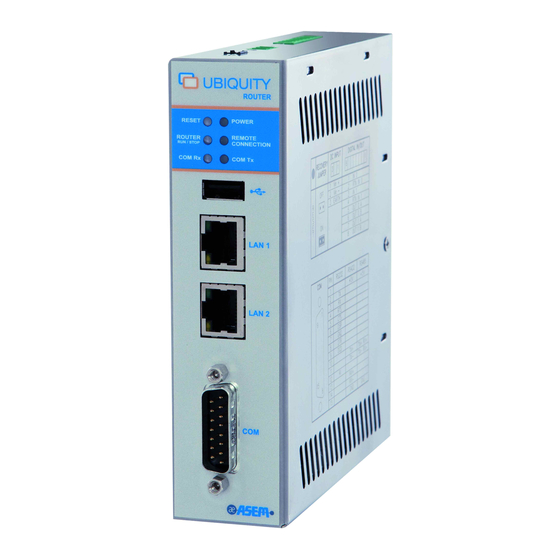
Page 18: Front View Rm10
SECTION 2 - Description 2.5 Front view RM10 Reset LED (Yellow) Run /Stop LED (Green/Red) COM Rx LED WAN ETH2 LAN ETH1 COM Tx LED (Green) Remote Connection LED (Green) Power LED (Green) - Page 19 Ubiquity Router family - User’s guide The following behaviors are defined: Steady lighted Blinking Continuous sequence of a blink codes with a short pause in between to report a status Single sequence of a blink code to report an event Status Description RESET...
-
Page 20: Front View Rk11
SECTION 2 - Description 2.6 Front view RK11 13 12 Figure 2 RK11 Reset LED (Yellow) Run /Stop LED (Green/Red) COM Rx LED WAN ETH2 LAN ETH1 COM Tx LED (Green) 2G/3G/3G+ Modem Activity 2G/3G/3G+ Modem Connection RF antenna connector Remote Connection LED (Green) Power LED (Green) - Page 21 Ubiquity Router family - User’s guide The following behaviors are defined: Steady lighted Blinking Continuous sequence of a blink codes with a short pause in between to report a status Single sequence of a blink code to report an event Status Description RESET...
-
Page 22: Front View Rm11
SECTION 2 - Description 2.7 Front view RM11 Figure 3 RM11 Reset LED (Yellow) Run /Stop LED (Green/Red) COM Rx LED WAN ETH2 LAN ETH1 COM Tx LED (Green) 2G/3G/3G+ Modem Activity 2G/3G/3G+ Modem Connection RF antenna connector Remote Connection LED (Green) Power LED (Green) - Page 23 Ubiquity Router family - User’s guide The following behaviors are defined: Steady lighted Blinking Continuous sequence of a blink codes with a short pause in between to report a status Single sequence of a blink code to report an event Status Description RESET...
-
Page 24: Up View
SECTION 2 - Description 2.8 UP view Figure 4 RK10 Reset button Restore factory defaults button DC Input Digital In / Out Antenna connector (RM only) RESET Forces the device restart. The command ensures a complete initiali- zation of all internal electronics and software. The visual feedback of the operation is returned by the RESET LED. -
Page 25: Right View
Ubiquity Router family - User’s guide This input works as “Connection mode”, also referred as “selector key” in- put. By default the status of this input is ignored. When the Ubiquity Router device is configured to handle the input (see “General options” in the Ubiquity Router device configuration chapter) it can be used to control from outside the connection to the server. -
Page 26: Left View
SECTION 2 - Description 2.10 Left view Figure 6 RK10 Full stainless steel enclosure Aeration holes 2.11 Rear view (RK11/RK11 ET – RM11 / RM11 ET) Figure 7 RK11/RM11 Wall book mounting plate holes DIN rail book mounting hook holes SIM card socket... -
Page 27: Rear View (Rk10/Rk10 Et-Rm10/Rm10 Et)
Ubiquity Router family - User’s guide 2.12 Rear view (RK10/RK10 ET-RM10/RM10 ET) Figure 8 RK10 Wall book mounting plate holes DIN book mounting hook holes... -
Page 28: Labels
SECTION 2 - Description 2.12.1 Labels On the side panels there are the following labels: Figure 9 RK10 LAN IP 192.168.0.1 Mask 255.255.255.0 WAN IP DHCP User admin Password admin MAC LAN code MAC WAN code Serial number Bar Code IMEI... -
Page 29: Figure 10 Rk10
Ubiquity Router family - User’s guide Figure 10 RK10 DC Input pinout Digital In / Out pinout CE marking Disposal Electrical information Model COM pinout Restore factory defaults button Reset button... -
Page 30: Antenna
SECTION 2 - Description Figure 11 RK11 SIM card insertion label 2.12.2 Antenna 2.12.2.1 Pentaband stilo antenna RK11 direct mount or panel mount using extension cable 0dBi 50 Ohms 48mm SMA-M Figure 12 Pentaband stilo antenna... -
Page 31: Figure 13 Pentaband Wall-Mount Antenna
Ubiquity Router family - User’s guide 2.12.2.2 Pentaband wall-mount antenna 5mt cable wall mount with 90° bracket IP67 2,5dBi 50 Ohms 248mm SMA-M Figure 13 Pentaband wall-mount antenna... -
Page 32: Figure 14 Pentaband Outdor Antenna
SECTION 2 - Description 2.12.2.3 Pentaband outdor antenna 3mt cable outdoor panel mount IP67 3,2dBi 50 Ohms 48x50mm ▪ SMA-M Figure 14 Pentaband outdor antenna... -
Page 33: Section 3
Ubiquity Router family - User’s guide SECTION Installation and connection... -
Page 34: Preparation For Installation
Check the package content for visible signs of transport damage and for completeness. In the case of damaged parts, contact your ASEM representative. Do not Note: install parts damaged during shipment. please refer to paragraph 2.3 Package. 3.3 Checking the operating conditions ... -
Page 35: Damage Due To Overheating
An inclined installation reduces the thermal convection of the device and the maximum permissible ambient temperature for operation. Please contact ASEM for details. The device may otherwise be damaged and its certifications and warran- ty will be void. -
Page 36: Mounting The Device
SECTION 3 – Installation and connection 3.6 Mounting the device 3.6.1 Wall mounting installation procedure The system can be installed on a panel as follows: Figure 15 Wall mounting installation procedure Install the hook as illustrated in the picture. Figure 16 Wall mounting installation procedure... -
Page 37: Figure 17 Wall Mounting Installation Procedure
Ubiquity Router family - User’s guide Drill the required holes on the housing panel according to the instructions detailed in the figure. There are 2 fastening points. Fastening can be made using stainless steel screws M4x20. Figure 17 Wall mounting installation procedure ... -
Page 38: Figure 21 Wall Mounting Installation Procedure
SECTION 3 – Installation and connection Figure 21 Wall mounting installation procedure Step 4: Tighten two screws. -
Page 39: Din Guide Mounting Installation Procedure
Ubiquity Router family - User’s guide 3.6.2 DIN guide mounting installation procedure The system can be installed on a DIN guide as follows: Figure 22 Wall mounting installation procedure Figure 23 Wall mounting installation procedure Install the DIN hook as illustrated in the picture. Figure 24 Wall mounting installation procedure... -
Page 40: Figure 25 Wall Mounting Installation Procedure
SECTION 3 – Installation and connection Hang the system to the DIN guide. Figure 25 Wall mounting installation procedure Example of correct installation. Figure 26 Wall mounting installation procedure... -
Page 41: Figure 27 Wall Mounting Installation Procedure
Ubiquity Router family - User’s guide To remove the system from the DIN guide: Lift the system up and release it from the DIN guide Figure 27 Wall mounting installation procedure... -
Page 42: Sim Installation
SECTION 3 – Installation and connection 3.7 SIM installation The SIM card is not provided with the product. The SIM card must be associated with a data traffic plan. The traffic plan must be properly chosen depending on foreseen traffic generated by the remote assistance sessions and SMS notification usage (for RM models). -
Page 43: Figure 30 Sim Card Insertion
Ubiquity Router family - User’s guide Pull the SIM card in the hole till you listen a “clic” Figure 30 SIM card insertion Figure 31 SIM card inserted (datail) -
Page 44: Antenna Installation
SECTION 3 – Installation and connection 3.7.1 Antenna Installation Pentaband stilo antenna 3.7.1.1 For dimension installation please refer to pararagraph 6.4 Figure 32 Pentaband stilo antenna installation Drill a 6,5mm hole on the metal. Max thickness 2mm 6,5mm hole Figure 33 Pentaband stilo antenna installation Recommended torque for mounting is 0.9 Nm. -
Page 45: Figure 34 Pentaband Wall-Mount Antenna Installation
Ubiquity Router family - User’s guide Pentaband wall mount antenna 3.7.1.2 For dimension installation please refer to pararagraph 6.4 Figure 34 Pentaband wall-mount antenna installation For dimension installation please refer to pararagraph 6.5 3.7.1.3 Pentaband outdor antenna For dimension installation please refer to pararagraph 6.6 Figure 35 Pentaband outdor antenna installation ... -
Page 46: Figure 36 Pentaband Outdor Antenna Installation
SECTION 3 – Installation and connection Max thickness 5mm Figure 36 Pentaband outdor antenna installation Recommended torque for mounting is 2.94 Nm. Maximum torque for mounting is 3.92 Nm. -
Page 47: Connecting The Device
Ubiquity Router family - User’s guide 3.8 Connecting the device 3.8.1 Notes on connection Ubiquity Router device must be installed in accordance with the indications contained in this operating instructions. These devices are intended to be connected to a “Secondary Circuit Over- voltage Category II”... -
Page 48: Connecting The Ethernet Ports
SECTION 3 – Installation and connection Figure 38 Power supply connection detail 3.8.4 Connecting the Ethernet ports The Routers have always two Ethernet ports, one referred as WAN, the other one referred as LAN. LAN for automation network Figure 39 Ethernet connection detail WAN for Internet connection When using the cable connection for Internet, it must be connected to the WAN... -
Page 49: Switching On And Testing The Ubiquity Router Device Device
Ubiquity Router family - User’s guide 3.8.5 Switching on and testing the Ubiquity Router device Device Connect the power supply cable to Ubiquity Router device. Switch the power supply on. The green POWER LED will light on. Figure 40 Power supply connection detail Please refer to the Ubiquity Control Center on-line help for all the details about how to configure and use Ubiquity Router device. -
Page 50: Connecting The Serial Port
A unique DB15 male connector hosts all serial protocols (please check par. 6.4.1 for pin-out details) so it is necessary to adapt this connection to plant needs; ASEM can supply connector adapters as optional parts but user can adapt DB15 connector by himself. -
Page 51: Figure 42 Adapters Detail
The line termination and polarization is normally realized by using resistors mounted internally to the standard Profibus / MPI connectors. The cable adapter provided by ASEM provides on the DB9-F connector side all the signals required by the MPI communication and line termination. -
Page 52: Connecting Digital I/O
SECTION 3 – Installation and connection 3.10 Connecting digital I/O In this section will be shown some example on how to connect the digital I/O to key, button and lamps. 3.10.1 IN0 - WAN connection enabling security key UBIQUITY ROUTER CONFIGURATION (DEFAULT) SENSE? -
Page 53: Out0 - Wan Connection Enabled Signalling
Ubiquity Router family - User’s guide 3.10.3 OUT0 - WAN connection enabled signalling DIGITAL 24V DC IN / OUT 200mA Figure 45 OUT0 – WAN connection enabling signal- OUT0A ling example OUT0B 24V DC 230V AC DIGITAL IN / OUT 200mA Figure 46 OUT0A... - Page 54 SECTION 3 – Installation and connection...
-
Page 55: Section 4
Ubiquity Router family - User’s guide SECTION Commissioning... -
Page 56: Configuring
Ubiquity Router device commissioning. Ubiquity Router device requires for the configuration Ubiquity Control Center version 2 or above. Control Center is available for download in the dedicated product section of the www.asem.it web site. 4.1.1 Ubiquity Router RM models... - Page 57 Ubiquity Router family - User’s guide Select TCP in the upper left list. Write the IP address of the Router (WAN or LAN port IP) Choose where to download the project into the Router specifying the “Upload Device Path”. Note: the project must be transferred to the “MMCMemory” data storage de- vice.
- Page 58 SECTION 5 – Commissioning a project figured to use the internal modem, you just need to configure the alarm thresholds according to the application requirements. Please see the Premium HMI Studio on-lien help for further information about how to setup alarm notification via SMS Note: Ubiquity RM models without integrated modem, DO NOT support alarm notification via SMS.
-
Page 59: Section 5
Ubiquity Router family - User’s guide SECTION Maintenance and care... -
Page 60: Maintaining & Cleaning
SECTION 6 – Maintenance and care 5.1 Maintaining & cleaning Ubiquity Router device is designed for maintenance-free operation except for the replacing of the battery backup when necessary. Attention: Do not use detergents, solvents, cleaners or objects that could scratch the surface. Attention: switch off the power before any cleaning operation. -
Page 61: Figure 51 Backup Battery Replacement
Ubiquity Router family - User’s guide Remove the screw as indicated in figure. Figure 51 Backup battery replacement Locate the battery position. Figure 52 Backup battery replacement... -
Page 62: Figure 53 Backup Battery Replacement
SECTION 6 – Maintenance and care Remove the battery. Figure 53 Backup battery replacement Figure 54 Backup battery replacement... -
Page 63: Backup And Restore
Ubiquity Router device. For more information please see the Ubiquity Control Center on-line manual or contact the ASEM support center. 5.3 Updating the system Ubiquity Router device is a hardware device that works thanks to a set of soft- ware components;... -
Page 64: Technical Support & Repairs
No action is requested by the user. The update is completed after the ASEM offers wide-ranging, complete after-sales technical support. The staff Ubiquity Router device is auto- who deal with this handle questions on the entire range of products skillfully, matically restarted. -
Page 65: Section 6
Ubiquity Router family - User’s guide SECTION Technical specifications... -
Page 66: Technical Specifications
Integrated sys- Operating System Microsoft Windows Embedded Com- System software characteristics tem software pact 7 (C7P) Other software ASEM Ubiquity runtime firmware System hardware characteristics Motherboard Model All-in-one, ASEM R171 Hardware with battery backup Processor ARM Cortex A8 - Freescale i.MX535 - 1 GHz... - Page 67 Ubiquity Router family - User’s guide Environmental characteristics Temp. RK10, Operation -0° ÷ +50°C RM10, RK11, Storage -20° ÷ +60°C RM11 Operation -20° ÷ +70°C Temp. RK10ET, Storage -30° ÷ +80°C RM10ET Table 6 Temp. RK11ET, Operation -20° ÷ +60°C Environmental characteristics RM11ET Storage...
- Page 68 SECTION 8 - Technical specifications Outdoor Panel antenna characteristics Electrical Antenna Standard 2G/3G/4G Operation Frequency (MHz) 698~960 MHz 1710~2170 MHz 2500~2800MHz Peak Gain 1.2 dBi 3.2dBi 2.5dBi Table 9 Average Gain -4.5 dB -2.5dB -4.5dB Outdor Panel antenna characteristics Efficiency VSWR <3.0:1 Impedance...
-
Page 69: Certificates And Approvals
Ubiquity Router family - User’s guide 6.2 Certificates and approvals ASEM’s products are compliant with European Directive 2004/108/CE concerning electromagnetic compatibility and Directive 2006/95/CE con- cerning the safety of electrical products, and subsequent variations. RoHs 2011/65/UE. Emission ... -
Page 70: Dimension Drawings
SECTION 8 - Technical specifications 6.3 Dimension drawings Figure 57 Dimensions... - Page 71 Ubiquity Router family - User’s guide Figure 58 Dimensions...
-
Page 72: Panel Antenna Drawing Dimensions
SECTION 8 - Technical specifications 6.4 Panel antenna drawing dimensions Figure 59 Panel antenna drawing dimensions... -
Page 73: Wall Mount Antenna Drawing Dimensions
Ubiquity Router family - User’s guide 6.5 Wall mount antenna drawing dimensions Figure 60 Wall mount antenna drawing dimensions Main bracket Back bracket 3”8L screw 4”25L screw 6”24L wall mount stud CFD 200 cable SMA(M) ST Heat shrink tube Housing Flexible whip... -
Page 74: Outdoor Panel Antenna Drawing Dimensions
SECTION 8 - Technical specifications 6.6 Outdoor panel antenna drawing dimensions Figure 61 Outdoor panel antenna drawing dimen- sions Housing top Housing bottom Gasket Multi tooth washer Nut M12 RG316 Heat shrink tube SMA(M) ST O-ring... -
Page 75: Ports Pinout
Ubiquity Router family - User’s guide 6.7 Ports PINOUT 6.7.1 COM1 – DB15M Serial Signal Isolated +5 VDC Transmit Data (RS-232) Receive Data (RS-232) Table 10 Request To Send COM1 – DB15M Serial Clear To Send Data Set Ready Isolated Ground Data Terminal Ready Carrier Detect... -
Page 76: Dc Input
SECTION 8 - Technical specifications 6.7.3 DC Input Signal Vin + Table 12 Vin - DC Input EARTH... - Page 77 Index of figures Figure 1 RK10 ..................................10 Figure 2 RK11 ..................................14 Figure 3 RM11 ................................... 16 Figure 4 RK10 ..................................18 Figure 5 RK10 ..................................19 Figure 6 RK10 ..................................20 Figure 7 RK11/RM11 ................................. 20 Figure 8 RK10 ..................................21 Figure 9 RK10 ..................................
- Page 78 Table 9 Outdor Panel antenna characteristics ........................62 Table 10 COM1 – DB15M Serial ............................69 Table 11 Digital In/Out ..............................69 Table 12 DC Input................................70 ASEM S.p.A. Via Buia, 4 33011 Artegna (UD) Italy Tel. +39/0432-9671 Fax. +39/0432-977465...
Need help?
Do you have a question about the Ubiquity RM10 and is the answer not in the manual?
Questions and answers
Hallo I have a RK10 router it's on but the lan ports is not blinking what could be the problem?
If the LAN ports on the ASEM Ubiquity RM10 router are not blinking, possible problems could include:
1. No Physical Connection – The Ethernet cable may not be properly connected to the LAN port.
2. Faulty Cable – The Ethernet cable might be damaged or not working properly.
3. No Network Activity – The connected device may be powered off or not transmitting data.
4. Hardware Issue – The LAN port on the router or the connected device may be malfunctioning.
5. Configuration Issue – The router settings may not be correctly configured for LAN communication.
Checking the cable, device status, and router configuration may help identify and resolve the issue.
This answer is automatically generated