Table of Contents
Advertisement
CARLO GAVAZZI
Carlo Gavazzi Controls SpA,
Via Safforze, 8 - 32100
Belluno (Italy)
A u t o m a t i o n
C o m p o n e n t s
Tel. +39 0437 931000,
Fax +39 0437 931021
EM24DIN USE IM ENG ITA ESP 8020769 031007
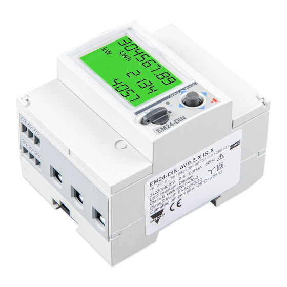
EM24 DIN
"Compact 3-phase Energy Analyzer"
LED
Fig. 1
Fig. 2
TAB 1
1
2
3
ENG- Displaying of water cubic meters
ITA- Visualizzazione contatore metri cubi acqua
ESP- Visualización metros cúbicos de agua
ENG- Displaying of gas cubic meters
ITA- Visualizzazione contatore metri cubi gas
ESP- Visualización metros cúbicos de gas
ENG- Displaying of phase-to-neutral system voltage
ITA- Visualizzazione tensione fase-neutro di sistema
ESP- Visualización tensión sistema fase a neutro
ENG- Displaying of phase-to-phase system voltage
ITA- Visualizzazione tensione fase-fase di sistema
ESP- Visualización tensión sistema fase a fase
ENG- Displaying of max values
ITA- Visualizzazione valori massimi
ESP- Visualización valores máx.
ENG- User ID
ITA- Identificatore Utente
ESP- ID, identificación de usuario
ENGLISH
I I JOYSTICK AND KNOB FUNCTIONS
Refer to fig.1. In the measurement mode: 1) push for at least 3 seconds to
enter programming; 2-3) to scroll the measurement pages according to tab.
3; 4-5) to display and scroll the information pages relevant to the pro-
grammed parameters and instrument firmware release (see TAB 5). In the
programming mode: 1) to access to the menu or enter the modified value;
2-3) to scroll the menus or increase/decrease the values to be modified; 4-5)
to scroll the menus or increase/decrease the values to be modified. The knob
(see fig.2) prevents from accessing the programming mode when in
posi-
tion. It allows the direct access to a selected page (among the available ones,
depending on the "APPLiCAt" parameter, see tab.3) when in "1", "2" and
positions. The frontal red LED (fig.2) flashes proportionally to the active
imported energy consumption if the selector is in "
- 1 - 2" position, and to
the reactive inductive energy consumption in "kvarh" position. Any kind of
negative (exported) energy and power will not be managed by the front LED.
I I DISPLAY LAYOUT
The display is divided into 3 lines (as illustrated by the dotted lines in the TAB
1 table). The engineering units are referred to the variable shown in the rele-
vant line. The "negative" symbols (∑, dmd) refer to all the displayed vari-
ables. To improve the display legibility, the EM24 uses some symbols (see
TAB 1). In case of "OVERFLOW", the instrument displays "EEEE": at the same
time the DMD calculation, the hour-counter and the energy meters functions
are inhibited and the alarm outputs are activated. The indication "EEEE" in a
single phase variable automatically implies the overflow condition of the rel-
evant system variable, and the PF indication is forced to "0.000".
I I MEASUREMENT PAGES AND INFORMATION PAGES
To display and scroll the measurement pages the joystick is to be moved to
direction 2 or 3 (see fig.1). According to the selected "APPLiCAt" parame-
ter (see tab.2), different measurement pages are available (see tab.3). To
display and scroll the information pages the joystick is to be moved to direc-
tion 4 or 5 (see fig.1).
I I BASIC PROGRAMMING AND RESET
To enter the complete programming mode the joystick is to be pressed in
direction 1 for at least 3 sec. (see fig.1): the knob (see fig.2) is NOT to be
in
(with the knob in this position, the access to programming is allowed
only for some of the menus, see tab. 7), otherwise the programming mode
is not allowed. Entering the programming mode, all the measurements and
control functions are inhibited.
00
: only for A, B, C and E applications and only with the knob in position
and moving the joystick towards direction 1 (see fig. 1), it will be possible to
reset the "Wdmd max" and "VAdmd max" values; the display will show "rESEt
no": set "YES" and confirm pushing the joystick towards direction 1 (this
action may be made only once from the switching on of the instrument).
PASS?: entering the right password (default value is 0) allows access-
01
ing the main menu. RESET: entering the password value 1357 allows
accessing the "reset" menu. "rESEt
"= peak dmd values reset;
"rESEt.dmd"= dmd values reset; "EnE
P.rES"= partial energy meter reset.
CnG PASS: it allows changing the password.
02
APPLiCAt: it allows selecting the pertinent
03
application (see tab.2).
ITALIANO
I I FUNZIONI DEL JOYSTICK E DEL SELETTORE
In modalità di misura: 1) Premere per almeno 3sec. per accedere alla program-
mazione; 2-3) scorre le pagine di misura (Tab 3); 4-5) visualizza e scorre le pagi-
ne di informazione relative ai parametri di programmazione e revisione firmwar-
re (vedi TAB 5). In modalità di programmazione: 1) conferma valore ed entra
nei sotto menù; 2-3) scorre i menù ed incrementa/decrementa i valori alfanume-
rici; 4-5) scorre i menù e incrementa/decrementa i valori alfanumerici. Il selet-
tore visibile in figura 2, oltre a bloccare l'ingresso in programmazione se posi-
zionata in
, permette un accesso diretto alle pagine di misura pre-selezionate
(Tab 3) nelle posizioni 1, 2 e
. Le pagine di misura cambiano a seconda della
modalità "APPLiCAt" selezionata. Il LED rosso frontale (fig.2) lampeggia pro-
porzionalmente al consumo di energia attiva totale importata se il selettore è in
posizione "
- 1 - 2" e al consumo di energia reattiva induttiva se in posizione
"kvarh". Ogni tipo di energia negativa (esportata) non è gestita dal LED.
I I LETTURA DISPLAY
Il display è suddiviso in tre "fasce" dette righe di lettura (come illustrato
nella immagine in tabella TAB 1 con le linee tratteggiate). Le unità di misu-
ra si riferiscono ai valori corrispondenti nelle rispettive righe di lettura ad
eccezione di quelle scritte in "negativo" (∑, dmd) che si riferiscono a tutti
i valori visualizzati dal display. Al fine di migliorare la chiarezza e l'immedia-
tezza della lettura dello strumento, EM24 utilizza alcuni simboli grafici (Tab1).
In caso di "OVERFLOW" lo strumento visualizza "EEEE": contemporaneamente le
funzioni di calcolo DMD, conta-ore e contatori di energia vengono inibite e le
uscite allarme vengono attivate. L'indicazione "EEEE" su una variabile di singola
fase si estende automaticamente alla corrispondente variabile di sistema e l'in-
dicazione PF viene portata a "0.000".
I I PAGINE DI MISURA E PAGINE INFORMAZIONI STRUMENTO
Per visualizzare e scorrere le pagine di misura agire sul joystick nelle direzioni
2-3 (fig 1). A seconda della modalità "APPLiCAt" preselezionata (TAB 2) ver-
ranno visualizzate le pagine di misura della tabella "TAB 3". Per visualizzare le
pagine informative dello strumento agire sul joystick nelle direzioni 4-5 (fig. 1).
I I PROGRAMMAZIONE BASE E RESET
Per accedere alla programmazione completa dello strumento premere il joy-
stick nella direzione 1 per almeno 3sec. (fig 1), il selettore di figura 2 NON si
deve trovare nella posizione di blocco programmazione indicata con il simbo-
lo
(con il selettore in questa posizione è permesso l'accesso alla program-
mazione solo ad alcuni menu vedi TAB 7). Quando si accede alla programma-
zione, si inibiscono tutte le funzioni di misura e controllo.
: solamente per le applicazioni A, B, C ed E e solamente con il selettore
00
in posizione
premendo il joystick nella direzione 1 (fig. 1), sarà possibi-
le resettare i valori "Wdmd max" e "VAdmd max": comparirà sul display
l'indicazione "rESEt
no" impostare "YES" e confermare premendo il joy-
stick in direzione 1 tale opzione può essere fatta solamente una volta dal-
l'accensione dello strumento.
PASS? : inserendo il valore di password corretto (di default 0) si accede al
01
menù principale. RESET: inserendo il valore di password 1357 si accede al
menù "reset". "rESEt
dmd"= reset dei valori dmd massimi; "rESEt.(dmd)"=
reset dei valori dmd; "EnE P.rES"= reset dei contatori di energia parziali.
CnG PASS: nuova password, personalizza la password.
02
APPLiCAt: seleziona l'applicazione pertinente (vedere tabella TAB. 2).
03
ESPAÑOL
I I FUNCIONES DEL JOYSTICK Y DEL INTERRUPTOR
Referente a la fig. 1. En el modo de medición: 1) presionar durante 3
segundos mín. para entrar al modo de programación; 2-3) Para avanzar
por las páginas de medición, según tab. 3. 4-5) Para visualizar y avanzar
por las páginas de información relevantes a los parámetros programados y
la versión firmware del instrumento (ver TAB 5). En el modo de programa-
ción: 1) para acceder al menú o introducir el valor modificado. 2-3) Para
avanzar por los menús o
aumentar/disminuir los valores
a modificar. 4-5) Para avanzar
por los menús o aumentar/dis-
minuir los valores a modificar. El
interruptor (ver fig. 2) evita acce-
der al modo de programación
cuando esté en la posición
Permite el acceso directo a la
página seleccionada (entre las
disponibles, dependiendo del
parámetro "APPLiCAt", ver tab. 3)
si está en las posiciones "1", "2" y
. El LED rojo frontal (fig. 2)
parpadea proporcionalmente al
consumo de energía activa
importada total si el selector
está en posición "
- 1 - 2" , y
al consumo de energía reactiva
si está en posicion "kvarh". No se indicará desde el LED frontal ninguna
clase de energía negativa (generada) ni potencia.
I I DISPOSICIÓN DEL DISPLAY
El display está dividido en 3 líneas, como se muestra con las líneas punteadas
en la tabla TAB 1. Las unidades ingenierísticas se refieren a la variable mos-
trada en la línea correspondiente. Los símbolos negativos (∑, dmd) se refie-
ren a todas las variables visualizadas. Para mejorar la interpretación del dis-
play, el EM24 usa ciertos símbolos (ver TAB 1). En caso de "SOBRERRANGO",
el equipo indica "EEEE" al mismo tiempo que el cálculo DMD, el contador
horario y las funciones de los medidores de energía se inhiben y las salidas de
alarma se activan. La indicación "EEEE" en una variable de fase monofásica
implica automáticamente la condición de sobrerrango de la variable del siste-
ma relevante y la indicación PF marcará "0.000".
I I PÁGINAS DE MEDICIÓN Y DE INFORMACIÓN
Para visualizar y avanzar por las páginas de medición, hay que mover el
joystick en dirección 2 ó 3 (ver fig. 1). Según el parámetro "APPLiCAt"
seleccionado (ver tab. 2) están disponibles diferentes páginas (ver tab. 3).
Para visualizar y avanzar por las páginas de información hay que mover el
joystick en dirección 4 ó 5 (ver fig. 1).
I I PROGRAMACIÓN BÁSICA Y PUESTA A CERO
Para entrar al modo de programación completo hay que presionar el joy-
stick en dirección 1 por al menos 3 seg. (ver fig. 1): el interruptor (ver fig.
2) NO debe estar en posición
(con el interruptor en está posición se
puede acceder sólo por algunos menus, ver tabla 7), de lo contrario no se
accede al modo de programación. En el modo de programación completa
del instrumento, todas las medidas y las funciones de control están inhibi-
das.
00
: solamente para las applicaciones A, B, C y E y solamente con el selec-
tor en posición " " hay que presionar el joystick en dirección 1 (fig. 1),
para poner a cero los valores "Wdmd max" y "VAdmd max": el display
mostrará la indicación "rESEt
no": seleccionar "YES" y confirmar pre-
sionando el joystick en dirección 1 (esta operación se puede hacer sólo una
vez desde el encendido del instrumento).
PASS? : introduciendo la clave correcta (valor por defecto 0) se acce-
01
de al menú principal. RESET: con el valor de clave 1357 se accede al menú
"reset" (puesta a cero). "rESEt
" = puesta a cero de valores pico dmd.
"rESEt.dmd": puesta a cero de los valores dmd. "EnE P.rES" = puesta a cero
del contador de energía parcial.
CnG PASS : permite cambiar la clave.
02
03
APPLiCAt : permite seleccionar la aplicación correspondiente (ver tab. 2).
TAB. 2
ENGLISH Application
ITALIANO Applicazione
A
Basic domestic Domestica base
Domestica base
b
Shopping centres
Centri commerciali
C
Advanced domestic
Domestica avanzata
d
Multi domestic (camping, marinas)
Multi-domestica (campeggi, porti turistici)
E
Solar energy
Energia solare
F
Industrial
Industriale
G
Advanced industrial
Industriale avanzata
H
Advanced industrial for power generation
Industriale avanzata per cogenerazione
TAB. 3
Line 1
No
Riga 1
1ª línea
1
Phase seq.
1
2
2
Phase seq.
3
Tot kWh (+)
4
kWh
A dmd max (5)
ENG- In this
5
Tot kvarh (+)
VA sys dmd
position
the
ENG-
Selector
6
kvarh
front
LED
position
which
blinks propor-
7 (1)
Totalizer 1 (2)
can be linked to
tionally to the
8 (1)
Totalizer 2 (2)
any of the variable
9 (1)
Totalizer 3 (2)
reactive energy
conbinations list-
10 (1)
kWh (+)
(kvarh) being
ed above (No.
mesured.
11 (1)
kWh (+)
from 1 to 31).
12 (1)
kWh (+)
ITA- In questa
13 (1)
kWh (+)
ITA- Posizione del
posizione
il
14 (1)
kvarh (+)
selettore associa-
L E D f r o n t a l e
15 (1)
kvarh (+)
bile ad ogni com-
lampeggia pro-
16 (1)
kvarh (+)
binazione di varia-
porzionalmen-
17 (1)
kvarh (+)
te all'energia
bili elencate sopra
18 (1)
kWh (+) X
reattiva (kvarh)
(No. da 1 a 31)
19 (1)
kWh (+) Y
misurata
20 (1)
kWh (+) Z
21
Total kvarh (-)
VA sys dmd
ESP- Posición del
ESP- En esta
22
Total kWh (-)
selector
que
posición
el
23
Hours
puede vincularse
LED
frontal
24
Hours
a cualquiera de
parpadea pro-
25
var L1
las combinacio-
porcionalmen-
26
VA L1
nes de variables
te a la energía
27
PF L1
arriba
descritas
r e a c t i v a
28
W L1
(de 1 a 31).
(kvarh)
en
29
A L1
medición.
30
V L1-2
31
V L1
ENGLISH- (1) The page is available according to the enabled functions (see pos. 04 or pos. 10 in the flowchart). (2) m 3 Gas, m 3 Water, kWh remote heating. (3) Hot or Cold (water). (4) The acti-
ve tariff is displayed with an "A" before the "t1-t2-t3-t4" symbols. Note: in case of alarm all the indications blink. When moving the joystick in any directions, the blinking will stop and will start
again after the joystick has not been moved for 60 sec., and only if the alarm is still active. During the programming phase there's a time out of 120 sec. expired which the instrument goes back
to the previously selected measuring page. (5) Highest dmd current among the three phases. There is a time out of 60sec that brings the scrolled page to the default one. ITALIANO- (1) La pagi-
na è disponibile a seconda della funzione abilitata (vedere pos. 04 o pos. 10 nel diagramma di flusso). (2) m 3 Gas, m 3 Acqua, kWh teleriscaldamento. (3) Hot (acqua calda) o Cold (acqua Fredda).
(4) La tariffa attiva è visualizzata con una "A" prima dei simboli "t1-t2-t3-t4". Note: in caso di allarme tutte le indicazioni lampeggiano. Agendo sul joystick in qualsiasi direzione il lampeggio si inter-
rompe per poi riprendere dopo 60sec. di inattività se la condizione di allarme persiste. In fase di programmazione c'è un tempo di time out di 120 sec., scaduto il quale lo strumento si riporta alla
pagina di misura preselezionata. (5) Massima corrente dmd tra le tre fasi. C'è un tempo di time-out di 60sec. scaduto il quale lo strumento passa dalla pagina visualizzata in quel momento alla pagi-
na definita dal menù "selector". ESPAÑOL- (1) La página está disponible según las funciones habilitadas (ver pos. 04 o pos. 10 en el diagrama de flujo). (2) m 3 Gas, m 3 Agua, lectura remota de
kWh de calefacción. (3) Caliente o fría (agua). (4) La tarifa activa se visualiza con una "A" antes de los símbolos "t1-t2-t3-t4". Nota: en caso de alarma todas las indicaciónes son parpadeantes.
Cuando se presiona el joystick en todas las direcciones, el parpadear termina y empieza de nuevo si el joystick no es activado para 60 sec., y solo si la alarma es ya activa. Durante la fase de
programación, transcurridos 120 segundos de pausa, el equipo vuelve a la página de medición anteriormente seleccionada. (5) Intensidad dmd máxima entre las tres fases. Transcurridos 60 segun-
dos de pausa el instrumento vuelve de la página visualizada en aquel momento a la página definida dal menu "selector".
TAB. 4
ENG- In applications A, b, C, d and G the flow direction of the current into the instrument does not affect the measurements.
ITA- Nelle applicazioni A, b, C, d, G il verso della corrente nello strumento non influisce nella misura.
SPA- En las aplicaciones A, b, C, d y G la dirección de la intensidad en el equipo no afecta a las medidas.
APPLICATION
REAL MEASUREMENTS
DISPLAYED VALUES
APPLICAZIONE
MISURE REALI
VALORI VISUALIZZATI
APLICACIÓN
MEDIDAS REALES
VALORES VISUALIZADOS
W, var, L PF
W, var
W, -var, C PF
W, -var
A - b - C - d - G
-W, var, C PF
W, -var
-W, -var, L PF
W, var
W, var, L PF
W
W, -var, C PF
W
E
-W, var, C PF
-W
-W, -var, L PF
-W
W, var, L PF
W, var
W, -var, C PF
W, -var
F
-W, var, C PF
-W, var
-W, -var, L PF
-W, -var
H
W, var, L PF
W, var, L PF
W, -var, C PF
W, -var, C PF
-W, var, C PF
-W, var, C PF
-W, -var, L PF
-W, -var, L PF
Aplicaciones ESPAÑOL
Domésticas básicas
Centros comerciales
Domésticas avanzadas
Múltiples apl. domésticas (inc. campings y puertos)
Energía solar
Industrial
Industrial avanzada
Industrial avanzada para cogeneración
Line 2
Line 3
APPLiCAt
Riga 2
Riga 3
A
b
C
d
E
F
G
2ª línea
3ª línea
VLN sys
Hz
x
x
x
x
x
x
VLL sys
Hz
x
x
W sys dmd
W sys dmd max
x
x
x
x
x
x
PArt
x
x
VA sys dmd max
x
x
x
x
VA sys
PArt
x
x
W sys
(3)
x
x
x
W sys
(3)
x
x
x
W sys
(3)
x
x
x
t1 (4)
W sys dmd
x
x
x
t2 (4)
W sys dmd
x
x
x
t3 (4)
W sys dmd
x
x
x
t4 (4)
W sys dmd
x
x
x
t1 (4)
W sys dmd
x
x
x
t2 (4)
W sys dmd
x
x
x
t3 (4)
W sys dmd
x
x
x
t4 (4)
W sys dmd
x
x
x
W X
User X
x
W Y
User Y
x
W Z
User Z
x
VA sys dmd max
x
W sys dmd
W sys dmd max
x
x
W sys
PF sys
x
x
x
var sys
PF sys
x
x
x
var L2
var L3
x
VA L2
VA L3
x
PF L2
PF L3
x
W L2
W L3
x
x
A L2
A L3
x
x
V L2-3
V L3-1
x
V L2
V L3
x
x
x
x
ENERGIES ENERGIE ENÉRGIA
DISPLAYED ENERGIES
NOTES
ENERGIE VISUALIZZATE
NOTE
ENERGÍAS VISUALIZADAS
NOTAS
kWh, kvarh
ENG- The negative energies are not counted at all
kWh, kvarh
ITA- Le energie negative non sono conteggiate
kWh, kvarh
ESP- Las energías negativas no se cuentan
kWh, kvarh
kWh
kWh
-kWh
-kWh
kWh, kvarh
kWh, -kvarh
-kWh, kvarh
-kWh, -kvarh
kWh, kvarh
kWh, -kvarh
-kWh, kvarh
-kWh, -kvarh
H
x
x
x
x
x
x
x
x
x
x
x
x
x
x
x
x
x
x
x
x
x
x
x
x
x
x
x
x
Advertisement
Table of Contents

Related Manuals for CARLO GAVAZZI EM24 DIN


Summary of Contents for CARLO GAVAZZI EM24 DIN
- Page 1 CARLO GAVAZZI Carlo Gavazzi Controls SpA, TAB. 2 Via Safforze, 8 - 32100 Belluno (Italy) ENGLISH Application ITALIANO Applicazione Aplicaciones ESPAÑOL A u t o m a t i o n C o m p o n e n t s Tel.
- Page 2 CARLO GAVAZZI Carlo Gavazzi Controls SpA, Via Safforze, 8 - 32100 Belluno (Italy) A u t o m a t i o n C o m p o n e n t s Tel. +39 0437 931000, Fax +39 0437 931021...
- Page 3 CARLO GAVAZZI Carlo Gavazzi Controls SpA, Via Safforze, 8 - 32100 Belluno (Italy) A u t o m a t i o n C o m p o n e n t s Tel. +39 0437 931000, Fax +39 0437 931021...
- Page 4 input; 4000VRMS output to supply input. Digital inputs: Number of inputs: Errori addizionali: grandezze di influenza: secondo EN50470-3, EN62053- Coppia min/max serraggio: 0,4Nm / 0,8Nm. Custodia DIN: Dimensioni 71 la escala del display. Histéresis: de 0 a 100% de la escala completa. Retardo a la ENGLISH I I SAFETY PRECAUTIONS 21, EN62053-23.
- Page 5 CARLO GAVAZZI Carlo Gavazzi Controls SpA, TAB. 2 Via Safforze, 8 - 32100 Belluno (Italy) FRANÇAIS Application DEUTSCH Applikationsbereich A u t o m a t i o n C o m p o n e n t s Tel. +39 0437 931000,...
- Page 6 CARLO GAVAZZI Carlo Gavazzi Controls SpA, Via Safforze, 8 - 32100 Belluno (Italy) A u t o m a t i o n C o m p o n e n t s Tel. +39 0437 931000, Fax +39 0437 931021...
- Page 7 CARLO GAVAZZI Carlo Gavazzi Controls SpA, Via Safforze, 8 - 32100 Belluno (Italy) A u t o m a t i o n C o m p o n e n t s Tel. +39 0437 931000, Fax +39 0437 931021...
- Page 8 (écriture et lecture): Tous les paramètres de configuration. Format de don- 48 bis 62Hz). Modell AV5 In: 5A, Imax: 10A; Un: 160 bis 480VLN (277 bis kondensierend @ 40°C) gemäß EN50470-1 und EN62053-23. FRANÇAIS I I PRÉCAUTIONS DE SECURITE nées: 1 bit de démarrage, 8 bit de données, pas de parité,1 bit d’arrêt. 830VLL).
Need help?
Do you have a question about the EM24 DIN and is the answer not in the manual?
Questions and answers