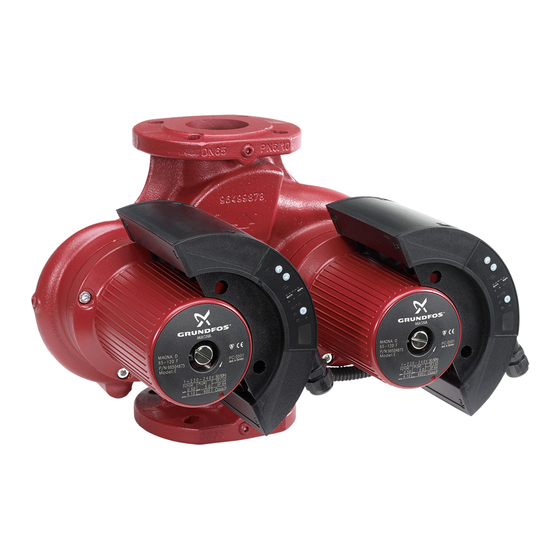
Grundfos Magna 32-120 Service Instructions Manual
Magna 2000 series 50/60 hz
Hide thumbs
Also See for Magna 32-120:
- Installation and operating instructions manual (39 pages) ,
- Instructions manual (9 pages) ,
- Installation and operating instructions manual (352 pages)
Advertisement
The pump must be serviced by a qualified person.
Service must be carried out in accordance with local regulations and accepted codes of good practice.
1.
Type identification ....................................................................................................................... 2
1.1
Nameplate...................................................................................................................................................... 2
1.2
Type key .......................................................................................................................................................... 2
2.
Dismantling and assembly .......................................................................................................... 3
2.1
Dismantling the pump................................................................................................................................4
3.
Fault correction............................................................................................................................. 5
3.1
Fault finding................................................................................................................................................... 5
3.2
Fault correction procedure.........................................................................................................................8
3.3
Fault indications via R100 fault log .......................................................................................................14
4.
Winding resistance..................................................................................................................... 15
GB
96558929 0804
Service instructions
MAGNA Series 2000
Magna 32-120, 40-120, 50-60, 50-120, 65-60, 65-120
50/60 Hz
1~
1 / 15
Advertisement
Table of Contents

Summary of Contents for Grundfos Magna 32-120
-
Page 1: Table Of Contents
Service instructions MAGNA Series 2000 Magna 32-120, 40-120, 50-60, 50-120, 65-60, 65-120 50/60 Hz The pump must be serviced by a qualified person. Service must be carried out in accordance with local regulations and accepted codes of good practice. Type identification ........................2 Nameplate.............................. -
Page 2: Type Identification
1. Type identification 1.1 Nameplate MAGNA 32-120F P/N: 96513625 PC: 0116 Model : E Made in Germany 230-240 V 50/60 Hz TF 110 0.15 IP 44 Class F 1.55 Pos. Description Pos. Description Type designation Production code (year + week) Product number Country of origin Model designation... -
Page 3: Dismantling And Assembly
2. Dismantling and assembly The pump must be serviced by a qualified person. Service must be carried out in accordance with local regulations and accepted codes of good practice. Before dismantling • Disconnect the electricity supply to the motor. • Close the isolating valves, if fitted, or drain the system, as the pumped liquid may be burning hot and under high pressure. -
Page 4: Dismantling The Pump
2.1 Dismantling the pump 2.1.1 Changing the position of the terminal box 1. Remove the inspection screw pos. 1 and the four screws pos. 2 in the stator housing, see Fig. 2. Turn the stator housing pos. 3 to the position required. If the stator housing has been prised/lifted off the pump housing, continue with point 2 in 2.1.2 Replacing the stator unit including the rotor... -
Page 5: Fault Correction
• that the requested sensor signal is available. 3.1.1 Printing of data registers The Grundfos R100 remote control enables the printing of status for the data registers by means of a Hewlett Packard infrared printer. The purpose of this is to ensure that the service technician can print out the data registers before starting the fault finding so that this print stating the original fault information can be enclosed, in case the product is re- turned to Grundfos. - Page 6 The following figure shows an example of a print of MAGNA Series 2000 pump data registers. 3.1.2 Fault log MAGNA Series 2000 pumps feature a fault log function: • The fault log function memory can recall the five latest faults. •...
- Page 7 3.1.3 Fault reading via R100 Possible fault and log can be read via R100 in the GENI menu and/or in the OPERATION menu. Fault indications Fig. 3 If the pump is faulty, the cause will appear in the display. The following fault indications can appear: •...
-
Page 8: Fault Correction Procedure
Pump is not running. Pump has been stopped... by means of the operating button via R100 via Grundfos GENIbus by the pump start/stop function. (Input on terminals STOP - is open meaning that 5 VDC can be measured across the terminals.) Pump is not running. - Page 9 Pump is not running. Pump has been stopped... by means of the operating button via R100 via Grundfos GENIbus by the pump start/stop function. Pump can run, however, even if there has previously been a fault. GENI module (if installed).
- Page 10 Pump is running but not as the expected pump type. Description Configuration error Explanation In case the terminal box cannot identify the stator type, the pump will run default as a 40-120 or a 65-120. Check by means of R100 which pump type the terminal Check/remedy box has registered: 1.
- Page 11 Pump is running at normal performance. Description Pump has been stopped due to fault and has restarted automatically. Explanation The fault may be due to fault in the GENI module or the LON module. Is the GENI module connected? Check/remedy YES: Proceed to points 2, 3 and 4.
- Page 12 The HALL sensor in the stator can be tested by measuring the winding resistance using an ordinary multime- ter. The test is more than 95% reliable. All three measurements must be OK. ≥ 1.7 MΩ ≥ 1.7 MΩ Approx. 21 kΩ ID 1 ID 2 ID 3...
- Page 13 HALL sensor in stator "+5V" Output Black White Wire colours ID 1 ID 2 ID 3 Fig. 6 Numbering of the pump's terminal block Comments to the diagram: 1. Coding definition Combination Pump ID 1 (1) ID 2 (3) ID 3 (5) GND (13) Undefined No connections...
-
Page 14: Fault Indications Via R100 Fault Log
3.3 Fault indications via R100 fault log The table shows the fault log possibilities in prioritized order. If two faults occurs at the same time, the fault with the highest priority will be shown! Code Fault indication Prior- Pump (faul Cause Remedy Start after fault... -
Page 15: Winding Resistance
4. Winding resistance Terminal number Pump type 4-10 6-12 5.0 Ω 5.0 Ω 5.0 Ω 32-120 5.0 Ω 5.0 Ω 5.0 Ω 40-120 11.7 Ω 11.7 Ω 11.7 Ω 50-60 3.7 Ω 3.7 Ω 3.7 Ω 50-120 11.7 Ω 11.7 Ω 11.7 Ω...


Need help?
Do you have a question about the Magna 32-120 and is the answer not in the manual?
Questions and answers