Table of Contents
Advertisement
Tel +1 (717) 767-6511
Fax +1 (717) 764-0839
www.redlion.net
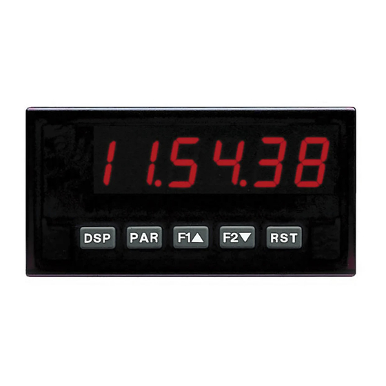
MODEL PAX - 1/8 DIN DIGITAL INPUT PANEL METERS
U L
C C
US LISTED
US LISTED
R
IND. CONT. EQ.
51EB
GENERAL DESCRIPTION
The PAX Digital Input Panel Meters offer many features and performance
capabilities to suit a wide range of industrial applications. Available in three
different models, PAXC Counter/Dual Counter, PAXR Rate Meter and the PAXI
which offers both counting and rate in the same package. Refer to pages 4 - 5 for
the details on the specific models. The PAXC and PAXR offer only the Setpoint
Option, while the PAXI is the fully featured version offering all the capabilities
as outlined in this bulletin as well as a slave display feature. The optional plug-in
output cards allow the opportunity to configure the meter for present applications,
while providing easy upgrades for future needs.
The meters employ a bright 0.56" LED display. The meters are available with
a red sunlight readable or standard green LED display. The intensity of the
display can be adjusted from dark room applications up to sunlight readable,
making it ideal for viewing in bright light applications.
The meters accept digital inputs from a variety of sources including switch
contacts, outputs from CMOS or TTL circuits, magnetic pickups and all
standard RLC sensors. The meter can accept directional, uni-directional or
Quadrature signals simultaneously. The maximum input signal varies up to 34
KHz depending on the count mode and function configurations programmed.
Each input signal can be independently scaled to various process values.
The Rate Meters provide a MAX and MIN reading memory with programmable
capture time. The capture time is used to prevent detection of false max or min
readings which may occur during start-up or unusual process events.
The meters have four setpoint outputs, implemented on Plug-in option cards.
The Plug-in cards provide dual FORM-C relays (5A), quad FORM-A (3A), or
either quad sinking or quad sourcing open collector logic outputs. The setpoint
alarms can be configured to suit a variety of control and alarm requirements.
Communication and Bus Capabilities are also available as option cards for
the PAXI only. These include RS232, RS485, Modbus, DeviceNet, and
Profibus-DP. Readout values and setpoint alarm values can be controlled
DIMENSIONS In inches (mm)
8. 8 . 8 . 8 . 8 . 8
A
B
C
SP1
SP2
SP3
SP4
DSP
PAR
F1
F2
RST
3.80
(96.5)
Note: Recommended minimum clearance (behind the panel) for
mounting clip installation is 2.1" (53.4) H x 5" (127) W.
1.95
(49.5)
.10
(2.5)
(104.1)
COUNT, DUAL COUNTER, RATE AND SLAVE DISPLAY
0.56" RED SUNLIGHT READABLE DISPLAY
VARIABLE INTENSITY DISPLAY
10 POINT SCALING FOR NON-LINEAR PROCESSES (PAXI)
FOUR SETPOINT ALARM OUTPUTS (W/Option Card)
RETRANSMITTED ANALOG OUTPUT (W/Option Card) (PAXI)
COMMUNICATION AND BUS CAPABILITIES (W/Option Card) (PAXI)
BUS CAPABILITIES; DEVICENET, MODBUS, AND PROFIBUS-DP
CRIMSON PROGRAMMING SOFTWARE (PAXI)
ETHERNET(W/ External Gateway) (PAXI)
NEMA 4X/IP65 SEALED FRONT BEZEL
through the bus. Additionally, the meters have a feature that allows a remote
computer to directly control the outputs of the meter. With an RS232 or RS485
card installed, it is possible to configure the meter using Red Lion's Crimson
software. The configuration data can be saved to a file for later recall.
A linear DC output signal is available as an optional Plug-in card for the PAXI
only. The card provides either 20 mA or 10 V signals. The output can be scaled
independent of the input range and can track any of the counter or rate displays.
Once the meters have been initially configured, the parameter list may be
locked out from further modification in its entirety or only the setpoint values
can be made accessible.
The meters have been specifically designed for harsh industrial environments.
With NEMA 4X/IP65 sealed bezel and extensive testing of noise effects to CE
requirements, the meter provides a tough yet reliable application solution.
SAFETY SUMMARY
All safety related regulations, local codes and instructions that appear in this
literature or on equipment must be observed to ensure personal safety and to
prevent damage to either the instrument or equipment connected to it. If
equipment is used in a manner not specified by the manufacturer, the protection
provided by the equipment may be impaired.
Do not use this meter to directly command motors, valves, or other actuators
not equipped with safeguards. To do so can be potentially harmful to persons or
equipment in the event of a fault to the meter.
CAUTION: Risk of Danger.
Read complete instructions prior to
installation and operation of the unit.
1.75
(44.5)
4.10
1
Bulletin No. PAXICR-H
Drawing No. LP0548
Released 01/11
CAUTION: Risk of electric shock.
12
16
20
13
17
21
14
18
22
15
19
23
24
25
1
2
3
5
6
7
4
8
9
10
11
3.60 (91.4)
1.75
(44.5)
Advertisement
Table of Contents

Related Manuals for red lion PAXI


Summary of Contents for red lion PAXI
-
Page 1: General Description
PAXC Counter/Dual Counter, PAXR Rate Meter and the PAXI A linear DC output signal is available as an optional Plug-in card for the PAXI which offers both counting and rate in the same package. Refer to pages 4 - 5 for only. -
Page 2: Table Of Contents
Programming the Meter....12 PAXI Counter/Rate Meter ....5 Factory Service Operations . -
Page 3: General Meter Specifications
ENERAL ETER PECIFICATIONS 1. DISPLAY: 6 digit, 0.56" (14.2 mm) red sunlight readable or standard green ELECTROMAGNETIC COMPATIBILITY Emissions and Immunity to EN 61326:2006: Electrical Equipment for 2. POWER: Measurement, Control and Laboratory use. AC Versions: Immunity to Industrial Locations: AC Power: 85 to 250 VAC, 50/60 Hz, 18 VA Electrostatic discharge EN 61000-4-2... -
Page 4: Paxc Counter
PAXC - 1/8 DIN C ODEL OUNTER 6-DIGIT LED DISPLAY (Alternating 8 digits for counting) DUAL COUNT QUAD INPUTS UP TO 3 COUNT DISPLAYS SETPOINT ALARM OUTPUTS (W/Plug-in card) PAXC SPECIFICATIONS ANNUNCIATORS: MAXIMUM SIGNAL FREQUENCIES: A - Counter A To determine the maximum frequency for the input(s), first answer the B - Counter B questions with a yes (Y) or no (N). -
Page 5: Paxi Counter/Rate Meter
PAXI - 1/8 DIN C ODEL OUNTER ETER COUNT, RATE AND SLAVE DISPLAY 6-DIGIT 0.56" RED SUNLIGHT READABLE DISPLAY VARIABLE INTENSITY DISPLAY 10 POINT SCALING (FOR NON-LINEAR PROCESSES) FOUR SETPOINT ALARM OUTPUTS (W/OPTION CARD) RETRANSMITTED ANALOG OUTPUT (W/OPTION CARD) ... -
Page 6: Optional Plug-In Output Cards
SPC3 ASIC Conformance: PNO Certified Profibus-DP Slave Device PAXI ANALOG OUTPUT CARD (PAXCDL) Baud Rates: Automatic baud rate detection in the range 9.6 Kbaud to 12 Mbaud Either a 0(4)-20 mA or 0-10 V retransmitted linear DC output is available Station Address: 0 to 125, set by rotary switches. -
Page 7: Installing The Meter
1.0 I NSTALLING THE ETER Installation While holding the unit in place, push the panel latch over the rear of the unit The PAX meets NEMA 4X/IP65 requirements when properly installed. The so that the tabs of the panel latch engage in the slots on the case. The panel unit is intended to be mounted into an enclosed panel. -
Page 8: Installing Plug-In Cards
3.0 I NSTALLING ARDS The Plug-in cards are separately purchased optional cards that perform To Install: specific functions. These cards plug into the main circuit board of the meter. The 1. With the case open, locate the Plug-in card connector for the card type to be Plug-in cards have many unique functions when used with the PAX. -
Page 9: Wiring The Meter
4.0 W IRING THE ETER b. Connect the shield to earth ground at both ends of the cable, usually when WIRING OVERVIEW the noise source frequency is above 1 MHz. Electrical connections are made via screw-clamp terminals located on the c. - Page 10 4.3 INPUT WIRING CAUTION: Sensor input common is NOT isolated from user input common. In order to preserve the safety of the meter application, the sensor input common must be suitably isolated from hazardous live earth referenced voltage; or input common must be at protective earth ground potential. If not, hazardous voltage may be present at the User Inputs and User Input Common terminals.
-
Page 11: Reviewing The Front Buttons And Display
Reset (Function key) *** Advances digit location in parameter values * Counters B, and C are locked out in Factory Settings (PAXC and PAXI only). ** Factory setting for the F1, and F2 keys is NO mode. *** Factory setting for the RST key is ... -
Page 12: Programming The Meter
6.0 P ROGRAMMING THE ETER OVERVIEW PROGRAMMING MENU Shaded areas represent program access that is model dependent. PROGRAMMING MODE ENTRY (PAR KEY) PROGRAMMING MODE EXIT (DSP KEY or at PAR KEY) The meter normally operates in the Display Mode. No parameters can be The Programming Mode is exited by pressing the key (from anywhere programmed in this mode. - Page 13 Input B is high, Input A rising edge when Input B is low, Input B rising edge when Input A is high, and Input B falling edge when Input A is low. PAXI: PRESCALER OUTPUT ENABLE * Quad X1 Adds Input A rising edge when User 1 is high.
- Page 14 COUNTER B OPERATING MODE COUNTER B RESET POWER-UP * Counter B may be programmed to reset at each meter power-up. Select the operating mode for Counter B. SELECTION MODE DESCRIPTION...
- Page 15 NOTE: When a user input is used to accept a quad or directional input communications Plug-in card is installed in the meter. signal, then that user input should be programmed for NO function. PROGRAMMING MODE LOCK-OUT PAXI: PRINT REQUEST AND RESET DISPLAYS Programming Mode is locked-out, as long as activated ...
- Page 16 MAINTAINED (LEVEL) RESET AND INHIBIT DEACTIVATE SETPOINT MAINTAINED (LEVEL) The meter deactivates the setpoints configured as , as long as activated The meter performs a reset and inhibits the displays configured as , as ...
- Page 17 6.3 MODULE 3 - D ISPLAY AND ROGRAM ARAMETERS 3-LOC PARAMETER MENU rAtE SP-n CNtLd SCFAC COdE Max Display Counter x Rate Display Counter x Scale Min Display Setpoint 1-4 Security Lock-out Display Lock-out Count Load Factor x Lock-out Access Code Lock-out...
- Page 18 Calculation.) The High Update Time must be higher than the Low Update Time and higher than the desired slowest readable speed (one divided by pulses per PAXI: RATE DISPLAY VALUE FOR SCALING POINT 1 second). The factory setting of 2.0, will force the display to zero for speeds below 0.5 Hz or a pulse every 2 seconds.
- Page 19 0 Hz. A linear relationship is formed between these points to yield a rate display value that corresponds to the incoming input signal rate. The PAXI Enter the corresponding Rate Input Value for the second Scaling Point by and PAXR are capable of showing a rate display value for any linear process.
- Page 20 When reset to count load action is selected, Counter C will reset to this value. at the same time for the math to be performed on the display values. See Serial Communications for details. (PAXI only) COUNTER C RESET POWER-UP * ...
- Page 21 6.6 MODULE 6 - S ETPOINT LARM ARAMETERS 6-SPt PARAMETER MENU SPSEL Lit-n OUt-n SUP-n ACt-n ASN-n SP-n trC-n tYP-n Setpoint Setpoint Output Power-up Setpoint Setpoint Setpoint Setpoint Boundary Select Annunciators Logic State Action Assignment Value Tracking Type Stb-n HYS-n tOFF-n tON-n...
- Page 22 With Latch action, the setpoint output activates when the rate value is equal to the setpoint value. The setpoint output remains PAXI & R: SETPOINT OFF DELAY * active until reset. If after reset, the rate value is greater than or ...
- Page 23 PAXC & I: SETPOINT RESET WITH DISPLAY RESET * PAXC & I: SETPOINT RESET WHEN SPn+1 DEACTIVATES * Select , so the setpoint output will deactivate (reset) when the Setpoint ...
- Page 24 communications plug-in cards. Discard the separate bulletin when using those serial plug-in cards with the PAXI. Also, this section does NOT apply to the DeviceNet, Modbus, or Profibus-DP communication cards. For details on the operation of the Fieldbus cards, refer to the bulletin shipped with each card.
- Page 25 SENDING SERIAL COMMANDS AND DATA Command String Examples: 1. Address = 17, Write 350 to Setpoint 1 When sending commands to the meter, a string containing at least one String: N17VM350$ command character must be constructed. A command string consists of a command character, a value identifier, numerical data (if writing data to the 2.
- Page 26 Auto/Manual Mode Register (MMR) ID: U Writing to this register (VW) while the analog output is in the Manual Mode This register sets the controlling mode for the outputs. In Auto Mode (0) the causes the output signal level to update immediately to the value sent. While in meter controls the setpoint and analog output.
- Page 27 (start bit of next byte). The receiver then continuously looks for the occurrence of the start bit. If 7 data bits and no parity is selected, then 2 stop bits are sent from the PAXI.
-
Page 28: Factory Service Operations
Please discard the separate literature when using the plug- in card with the PAXI. Enter the display value within the selected Analog Assignment that corresponds to the low limit of the type selected. The decimal point is determined by the decimal point setting of the assigned ANALOG TYPE counter or rate. -
Page 29: Troubleshooting
3. Using the chart below, step through the five selections to be calibrated. At When Analog Out recalibration is required (generally every 2 years), it each prompt, use the PAXI arrow keys to adjust the output so that the should be performed by qualified technicians using appropriate equipment. -
Page 30: Parameter Value Chart
Programmer ________________ Date ________ PAX Model Number _________ Meter# _____________ Security Code __________ Rate Input Parameters - PAXI & R only Counter A & B Input Parameters - PAXC & I only FACTORY FACTORY DISPLAY PARAMETER USER SETTING... -
Page 31: Limited Warranty
The Company disclaims all liability for any affirmation, promise or representation with respect to the products. The customer agrees to hold Red Lion Controls harmless from, defend, and indemnify RLC against damages, claims, and expenses arising out of subsequent sales of RLC products or products containing... -
Page 32: Programming Overview
PROGRAMMING QUICK OVERVIEW...
Need help?
Do you have a question about the PAXI and is the answer not in the manual?
Questions and answers