
Related Manuals for YOKOGAWA 2769


Summary of Contents for YOKOGAWA 2769
- Page 1 User's 2769 Manual Portable Double Bridge IM 2769-10E IM 2769-10E 6th Edition: Oct. 2017 (YMI)
- Page 2 Before using this product, thoroughly read this manual to understand how to use it properly. Contact information of Yokogawa offices worldwide is provided on the following sheet. PIM 113-01Z2:...
-
Page 3: Cautionary Notes For Safe Use Of The Product
If you use the instrument in any way other than as instructed in this manual, the instrument’s protective measures may be impaired. YOKOGAWA is by no means liable for any damage resulting from use of the instrument in contradiction to these cautionary notes. - Page 4 • Do not use a mixture of different types of batteries or a mixture of old and new batteries. If the instrument will not be used for a prolonged period, remove the batteries before storage. The battery fluid will leak more readily during long-term storage, resulting in an instrument malfunction. IM 2769-10E ― iii ―...
-
Page 5: Table Of Contents
6.2.2 Error due to Potential Lead ......13 7. CIRCUIT DIAGRAM AND PARTS LIST ......15 IM 2769-10E ― iv ―... -
Page 6: General
1. GENERAL The Portable Double Bridge 2769 is quite convenient with low resistance measurement from 1 mΩ to 110 Ω. This double bridge contains an electronic galvanometer and bridge power supply to facilitate the operation. 2. SPECIFICATIONS Measuring Range: 0.100 mΩ to 110.0 Ω... - Page 7 Approx. 196 × 226 × 130 mm (including handle and rubber feet.) Weight: Approx. 2.6 kg (5.7lbs) Accessories: Plug (A1025WX) User’s Manual Carrying case (B9350AW) Optional accessories: Standard Resistor 277100 (0.01 Ω ±0.1%, with three leadwires) Approx. 30 × 175 × 63 mm Approx. 0.25 kg IM 2769-10E ― 2 ―...
-
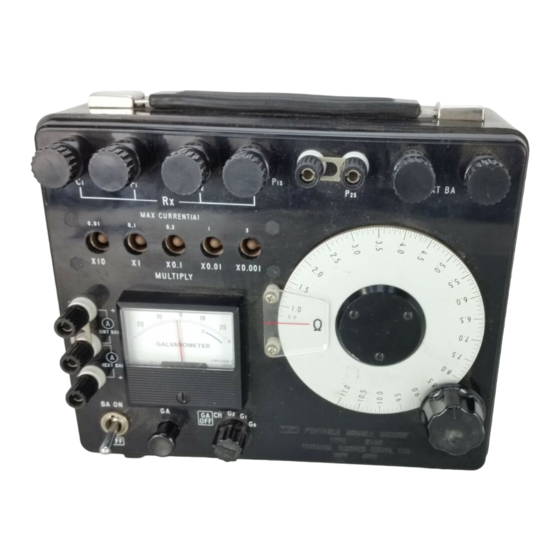
Page 8: Component Names And Functions
This switch turns on/off the power to the bridge. [4] Galvanometer Button Switch The galvanometer is connected to the bridge by depressing this switch. This switch is locked by turning it clockwise or counterclockwise while keeping it depressed. IM 2769-10E ― 3 ―... - Page 9 This is one of the potential terminals to which the Standard Resistor 2771 is connected. [10] EXT. BA Terminals An external battery is connected across these terminals. The minus (-) side of the terminals is one of the current terminals to which the External Standard Resistor is connected. IM 2769-10E ― 4 ―...
- Page 10 Since two batteries are used in parallel connection, replace them with two new ones at a time. Note that use of old battery in combination with new one will result in short battery life. Fig. 3.2 Removal of the Battery Cover A’ Fig. 3.3 Location of Batteries IM 2769-10E ― 5 ―...
- Page 11 Battery EXT BA MAX CURRENT (A) 0.01 ×10 ×1 ×0.1 ×0.01 ×0.001 MULTIPLY Ω (INT BA) (EXT BA) BA ON Ammeter Fig. 3.4 (a) Connection for External Battery Fig. 3.4 (b) Connection for Rx terminal IM 2769-10E ― 6 ―...
-
Page 12: Operating Instructions
If the indication is on the minus (-) side in the beginning of this adjustment, reduce the dial value and obtain zero indication in the same manner as above. If more sensitivity is required, select G position first, and G IM 2769-10E ― 7 ―... - Page 13 Rx = × [Ω] indication standard resistor 2771 Standard Resistor 0.01 Ω EXT BA MAX CURRENT (A) 0.01 2769 ×10 ×1 ×0.1 ×0.01 ×0.001 Portable Double Bridge MULTIPLY Fig. 4.1 Connection for External Standard Resistor IM 2769-10E ― 8 ―...
-
Page 14: Accessories
When an ammeter is used for monitoring current through Rx, remove the short-bar INT. BA (or EXT. BA ) terminals and the ammeter is connected to these terminals. For current monitoring, DC Ammeter 2051 (0.3/1/3/10/30 A) is recommended. IM 2769-10E ― 9 ―... -
Page 15: Cautions
0.5% at 1.0 and 10 on the dial scale. For this check, use of the 2792A or 2792 Series standard resistor is recommended. (2792 Series have been discontinued.) IM 2769-10E ― 10 ―... -
Page 16: Calibration Of Standard Resistor
Resistance value of 100 × variable standard resistor Calibrated value of measuring arm dial Resistance value of standard resistor 1000 Ω Potential leads to R Current leads Plug Fig. 5.1 Calibration of Built-in Standard Resistors IM 2769-10E ― 11 ―... -
Page 17: Principle Of Operation
Where is the lead resistance from the terminal Ps of S to the terminal Px of X. The 2769 double bridge is designed so that the fixed resistors and slide resistors have the following relationship: N = n and M = m Therefore, –... -
Page 18: Error Due To Potential Lead
1.005. Therefore, (1 + N = 0.005N (6.6) Model 2769 bridge is designed so that the N = 21 Ω when the measuring dial scale is minimum (1.0). Substituting N = 21 Ω for equation (6.6), N = 110 mΩ... - Page 19 S. (Ω) Lead Resistance at Potential Terminal 9 10 11 Dial Scale Fig. 6.2 Error due to Potential Lead IM 2769-10E ― 14 ―...
-
Page 20: Circuit Diagram And Parts List
13.24 Ω 120 Ω 390 Ω 1897 Ω 13.24 Ω 1897 Ω (INT.BA) (EXT.BA) 120 Ω 390 Ω 0.3 Ω R101 10 kΩ R102 1 kΩ R103 100 Ω R104 1 MΩ R105 18 Ω IM 2769-10E ― 15 ―... - Page 21 Printed in Japan...
Need help?
Do you have a question about the 2769 and is the answer not in the manual?
Questions and answers