Table of Contents
Advertisement
WARNING: If the information in this manual is not
followed exactly, a fire or explosion may result causing
property damage, personal injury or loss of life.
— Do not store or use gasoline or other flammable va-
pors and liquids in the vicinity of this or any other
appliance.
— WHAT TO DO IF YOU SMELL GAS
• Do not try to light any appliance.
• Do not touch any electrical switch; do not use any
phone in your building.
• Immediately call your gas supplier from a neighbor's
phone. Follow the gas supplier's instructions.
• If you cannot reach your gas supplier, call the fire
department.
— Installation and service must be performed by a quali-
fied installer, service agency or the gas supplier.
WARNING: This appliance is equipped for natural and
propane gas. Field conversion is not permitted other than
between natural or propane gases.
Questions, problems, missing parts? Before returning to your retailer, call
our customer service department at 1-855-607-6557, 8:00 am - 4:30 pm EST,
Monday through Friday or email info@factorybuysdirect.com
VENT-FREE GAS STOVE
OWNER'S OPERATION AND
INSTALLATION MANUAL
MODELS
FDSR25 & FDSR25GF
PFS
®
US
Advertisement
Table of Contents

Related Manuals for Duluth Forge FDSR25

Summary of Contents for Duluth Forge FDSR25
- Page 1 VENT-FREE GAS STOVE OWNER’S OPERATION AND INSTALLATION MANUAL MODELS FDSR25 & FDSR25GF ® WARNING: If the information in this manual is not followed exactly, a fire or explosion may result causing property damage, personal injury or loss of life. — Do not store or use gasoline or other flammable va- pors and liquids in the vicinity of this or any other appliance.
-
Page 2: Table Of Contents
TABLE OF CONTENTS Safety ............3 Operation ..........18 Specifications ..........4 Inspecting Burners........22 Qualified Installing Agency ......5 Care And Maintenance ......23 Product Features ........5 Electrical ..........24 Local Codes..........5 Troubleshooting ........26 Product Identification ......... 6 Service Hints ........... -
Page 3: Safety
SAFETY IMPORTANT: Read this owner’s WARNING: Any change to manual carefully and completely this stove or its controls can be before trying to assemble, dangerous. operate, or service this stove. Improper use of this stove can WARNING: Do not allow fans cause serious injury or death to blow directly into stove. -
Page 4: Specifications
SAFETY 1. Do not place Propane/LP supply tank(s) 9. Turn stove off and let cool before servic- inside any structure. Propane/LP supply ing. Only a qualified service person should tank(s) must be placed outdoors. service and repair stove. 2. This stove shall not be installed in a bed- 10. -
Page 5: Qualified Installing Agency
QUALIFIED INSTALLING AGENCY Only a qualified agency should install and a) Installing, testing, or replacing gas piping replace gas piping, gas utilization equipment or accessories, and repair and equipment ser- b) Connecting, installing, testing, repairing, vicing. The term “qualified agency” means any or servicing equipment;... -
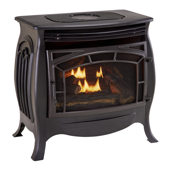
Page 6: Product Identification
PRODUCT IDENTIFICATION Stove Door Screen Logs Stove Controls (Inside Panel) Figure 1 - Vent-Free Stove UNPACKING 1. Remove top inner pack. 6. Rotate door handle and open door. 2. Tilt carton so that stove is upright. 7. Carefully remove logs. 3. -
Page 7: Air For Combustion And Ventilation
AIR FOR COMBUSTION AND VENTILATION WARNING: This heater shall WARNING: If the area in which not be installed in a confined the heater may be operated does space or unusually tight con- not meet the required volume for struction unless provisions are indoor combustion air, combus- provided for adequate combus- tion and ventilation air shall be... -
Page 8: Installation
AIR FOR COMBUSTION AND VENTILATION Ventilation Air From Outdoors Provide extra fresh air by using ventilation grills or ducts. You must provide two perma- Ventilated Outlet nent openings: one within 12" of the ceiling Attic and one within 12" of the floor. Connect these Outlet items directly to the outdoors or spaces open To Attic... -
Page 9: Check Gas Type
INSTALLATION CONNECTING ELECTRICAL This stove is designed to sit directly on the SUPPLY floor or on a mantel base. IMPORTANT: You must maintain minimum This stove requires an 120V electrical outlet wall and ceiling clearances during installation. within 4 feet of the unit. This is a power supply The minimum clearances are shown in Figure for the remote receiver located in the bottom 7. - Page 10 INSTALLATION GAS SELECTION This appliance is factory preset for propane/LP gas. No changes are required for connecting to propane/LP. Only a qualified installer or service WARNING: Make sure Regulator Cap is in the appropriate position ADVERTENCIA: Asegúrese la tapa del regulador esté en la posición adecuada, as shown in diagrams.
- Page 11 INSTALLATION 2. Apply thread sealant to the threads on Use only the cap supplied on the the connection fitting. While pushing in, regulator. Do not use an off the rotate the fitting clockwise until the threads shelf pipe plug. This can damage engage the regulator.
- Page 12 INSTALLATION CONNECTING TO GAS SUPPLY CAUTION: For natural gas, WARNING: A qualified ser- check your gas line pressure vice technician must connect before connecting stove to gas stove to gas supply. Follow all line. Gas line pressure must be local codes. no greater than 9"...
- Page 13 INSTALLATION For propane/LP installations, apply pipe WARNING: Test all gas piping joint sealant lightly to male threads. This will and connections for leaks after prevent excess sealant from going into pipe. Excess sealant in pipe could result in clogged installing or servicing. Correct stove valves.
-
Page 14: Checking Gas Connections
INSTALLATION CHECKING GAS CONNECTIONS valve for propane/LP (see Figure 14 or WARNING: Test all gas piping 15). Apply a noncorrosive leak detection and connections for leaks after fluid to all joints. Bubbles forming show a installing or servicing. Correct leak. all leaks at once. - Page 15 INSTALLATION 4. Check all joints from equipment shutoff 6. Light stove (see Lighting Instructions on valve to control valve (see Figure 14 or page 18). Check all other internal joints 15, page 14). Apply a noncorrosive leak for leaks. detection fluid to all joints. Bubbles form- 7.
- Page 16 INSTALLATION INSTALLING LOGS It is very important to install the logs ex- WARNING: Failure to posi- actly as instructed. Do not modify logs. tion the parts in accordance Use only logs supplied with stove. Each with these diagrams or failure log is marked with a number.
- Page 17 INSTALLATION 5. Install hole in log #4 onto pin on the left side Log #5 of log #2, with one end resting on log #3. 6. Install hole in log #5 onto pin on the right Log #4 Log #6 side of log #1, with one end resting on log #2.
-
Page 18: Operation
OPERATION FOR YOUR SAFETY READ BEFORE LIGHTING not use any phone in your building. WARNING: If you do not fol- • Immediately call your gas supplier low these instructions exactly, a from a neighbor’s phone. Follow the fire or explosion may result caus- gas supplier’s instructions. - Page 19 OPERATION Note: If pilot does not stay lit, refer to 11. If stove will not operate, follow the instruc- tions To Turn Off Gas To Appliance, and Troubleshooting, pages 26 though 29. Also contact a qualified service technician call your service technical or gas supplier. or gas supplier for repairs.
-
Page 20: Remote Control Operation
OPERATION REMOTE CONTROL SYSTEM Programming the Remote and Receiver Key Settings The remote and receiver must be “learned” ON - Operates unit to on position, manually to one another. operated solenoid ON. To prepare the receiver box for learning, use OFF - Operates unit to off position, manually a pen or small screwdriver to gently press operated solenoid OFF. - Page 21 OPERATION Setting°F/°C Scale 2. Press and hold the SET key until the de- The factory setting for temperature is °F. To sired set temperature is reached. The LCD change this setting to °C, press the ON key screen set numbers will increase from 45° and the OFF key on the remote control at the to 99°...
-
Page 22: Inspecting Burners
INSPECTING BURNERS IMPORTANT: Owner’s should check pilot flame pattern and burner flame pattern often. Incorrect flame patterns indicate the need for cleaning (see Care and Maintenance, page 23 or service. WARNING: Only a qualified service person should service and repair stove. This includes maintenance requiring replacement or alteration of components. -
Page 23: Care And Maintenance
CARE AND MAINTENANCE WARNING: Turn off stove and let cool before servicing. CAUTION: You must keep control areas, burner, and circulating air passageways of stove clean. Inspect these areas of stove before each use. Have stove inspected yearly by a qualified service techni- cian. -
Page 24: Electrical
CARE AND MAINTENANCE ODS/PILOT Ignitor Natural Gas Thermocouple CAUTION: Never use a wire, Electrode Burner needle, or similar object to clean Propane/LP Gas Burner ODS/pilot. This can damage ODS/ pilot unit. Use a vacuum cleaner, pressurized air, or a Pilot Air small, soft bristled brush to clean. -
Page 25: Electrical Wiring
ELECTRICAL ELECTRICAL WIRING Any electrical re-wiring of this stove must be WARNING: Never attempt to done by a qualified electrician. This wiring service stove while it is plugged must be done in accordance with local codes in, operating, or hot. Burns and and/or in Canada with the current CSA C22.1 Canadian Electrical Code, and for US instal- electrical shock could result. -
Page 26: Troubleshooting
TROUBLESHOOTING WARNING: If you smell gas: • Shut off gas supply. • Do not try to light any appliance. • Do not touch any electrical switch; do not use any phone in your building. • Immediately call your gas supplier from a neighbor’s phone. Fol- low the gas supplier’s instructions. - Page 27 TROUBLESHOOTING Problem Possible Cause Corrective Action When ignitor button is 1. Ignitor electrode is posi- 1. Replace electrode. pressed in, there is no tioned wrong. Ignitor elec- spark at ODS/pilot trode is broken. 2. Ignitor electrode is not con- 2. Replace ignitor cable nected to ignitor cable.
- Page 28 TROUBLESHOOTING Problem Possible Cause Corrective Action Burner(s) does not light 1. Burner orifice is clogged. 1. Clean burner orifice (see after ODS/pilot is lit Care and Maintenance, page 23) or replace burner orifice. 2. Burner orifice diameter is too 2. Replace burner orifice. small.
-
Page 29: Service Hints
TROUBLESHOOTING Problem Possible Cause Corrective Action Heater produces un- 1. Heater is burning vapors 1. Ventilate room. Stop using wanted odors. from paint, hair spray, glues, odor causing products while etc. See IMPORTANT state- heater is running. ment, page 26. 2. -
Page 30: Parts
PARTS MODEL FDSR25 & FDSR25GF www.factorybuysdirect.com 200257-01A... -
Page 31: Replacement Parts
PARTS MODELS FDSR25 & FDSR25GF This list contains replaceable parts for your stove. When ordering replacement parts, follow the instructions listed under Replacement Parts. Item Part # Description BL016-07 Blower Mount Panel SL005-01A Blower Bracket Door Assembly ND0310A-400-P-PU2 ODS Pilot... -
Page 32: Warranty
WARRANTY KEEP THIS WARRANTY Model _______________________________ Serial No. ____________________________ Date Purchased _______________________ Keep receipt for warranty verification. REGISTER YOUR PRODUCT AT WWW.FACTORYBUYSDIRECT.COM FACTORY BUYS DIRECT LIMITED WARRANTIES New Products Standard Warranty: Factory Buys Direct warrants this new product and any parts thereof to be free from defects in material and workmanship for a period of one (1) year from the date of first purchase from an authorized dealer provided the product has been installed, maintained and operated in accordance with Factory Buys Direct’s warnings and instructions.
Need help?
Do you have a question about the FDSR25 and is the answer not in the manual?
Questions and answers
where are the burner air vents located for my dutch forgue fdsr25 lp heater