Advertisement
Quick Links
I n s t a l l a t i o n I n s t r u c t i o n s
DO NOT OPERATE DEVICE WHILE DRIVING. PERFORM ALL ADJUSTMENTS OR
CHANGES WHILE VEHICLE IS STOPPED. CHANGING A SETTING WHILE UNDER WAY
CAN INTERFERE WITH YOUR ATTENTION TO THE ROADWAY
PLEASE READ ALL DIRECTIONS
BEFORE STARTING INSTALLATION
2191 Mendenhall Drive North Las Vegas, NV 89081 (800) 992-4993 www.powercommander.com
Parts List
1
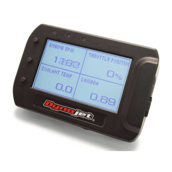
POD-300 Module
1
USB Cable
1
CAN cable
1
Installation Guide
2
Dynojet Decals
2
Velcro
1
Alcohol swab
POD300 - 1
Advertisement

Related Manuals for Dynojet POD-300

Summary of Contents for Dynojet POD-300
-
Page 1: Parts List
Parts List POD-300 Module USB Cable I n s t a l l a t i o n I n s t r u c t i o n s CAN cable Installation Guide Dynojet Decals Velcro Alcohol swab DO NOT OPERATE DEVICE WHILE DRIVING. PERFORM ALL ADJUSTMENTS OR CHANGES WHILE VEHICLE IS STOPPED. -
Page 2: Installing The Module
INSTALLING THE MODULE Optional mount shown - part #61300062 •The unit can be secured as needed to the vehicle using the supplied velcro or suitable mount. Make sure the unit will not interfere with the operation and/or steering of the vehicle. •The mounting holes on the back of the module use the stan- dard AMP style pattern. •Connect the supplied cable into the port on the side of the module and run the other end of the cable to an open CAN port of the PCV network. •This can connect to the PCV, Ignition Module or SFM. Whichever has an open CAN port. If your network currently has a CAN termination plug occu- pying the open port then you can remove the CAN termination plug. It will no longer be necessary. Programmable warning lights •Enter Main Menu •Scrolls down thru options. To move up continue to last selection 4 pin connection cable •Start/Stop logging 8 pin port •Enter selection Not used for this application •Scroll thru the 4 templates •Back to previous screen USB port MAIN MENU GAUGE VIEW GAUGE VIEW - Setup your channels to display You can view up to 4 channels at a time. From the main CONFIGURE ALARMS - Setup the 3 lights to menu go to GAUGE VIEW. Choose which screen you want... - Page 3 CONFIGURE ALARMS WB2 SETUP Alarms can be setup based on 1-3 channels and trig- WB2 LAMBDA SETUP gered by less than or greater than. O2 Out Threshold - .9 -1.1, default value = 1 - Sets up the Narrowband O2 Out function on the Wideband 2 (green 1 channel alarm example: wire). Changing this value will change the AFR that WB2 RED light is triggered when ENGINE RPM is greater switches the narrowband signal around. For example, if using than 10000rpm a value of .95, the WB2 will emulate a narrowband voltage signal that switches to rich if the Lambda reading is lower 2 channel alarm example: than .95, and lean if the Lambda reading is higher than .95 YELLOW light is triggered when AFR is greater than 14.0 AND greater than 60% throttle Lambda Smoothing - smooths, or averages, the AFR and Lambda channels. Lower values will result in the highest 3 channel alarm example: resolution, minimal latency, and would be preferred in GREEN light is triggered when AFR is greater than 12.8 situation where you are datalogging. AND less than 13.8 AND greater than 10% throttle Stoich Value - Predetermined stoichiometric values for DATA LOGGING different fuels.
- Page 4 CONTRAST - Adjust the screen contrast 0-100 Check www.powercommander.com download section BRIGHTNESS - Adjust the brightness of the screen EXPORTING and VIEWING LOG FILES 0-100. This will only be visible when unit has power from the vehicle. Download Power Core software by going to www.dynojet. com and click on Downloads and go to Software. This will MODE - Flip the orientation of the screen download the complete Power Core Suite. This module will use the POD-300 and WinPep 8 Data Center programs. Once you open the POD-300 program it will automatically retrieve any logs stored in the module. Click on the log file you want to export and then click on either: Export to WinPep8 Data center - Choose output folder location then click Export CSV. Data Center opens for you. Click on the NONE on the X and Y axis of the graph to choose which channels you want to view. Only channels logged will be shown as an option. Export to CSV file - saves file to destination file to be viewed in Microsoft Excel format.
Need help?
Do you have a question about the POD-300 and is the answer not in the manual?
Questions and answers