Table of Contents
Advertisement
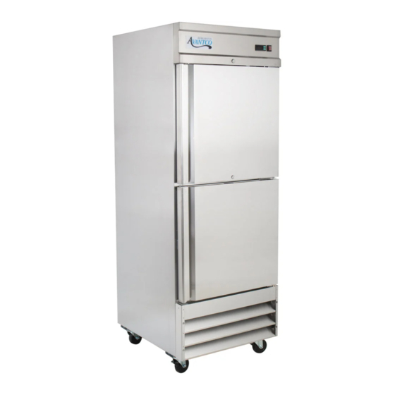
COMMERCIAL REACH-IN REFRIGERATOR & FREEZER
FOR USE BY QUALIFIED SERVICE TECHNICIANS
REACH-IN MODELS:
A Series:
SERVICE MANUAL
178A19FHC
178A19RHC
178A23FHC
178A23RHC
178A49FHC
178A49RHC
SS Series:
178SS1F2HC
178SS1FHC
178SS1R2HC
178SS1RGHC
178SS1RHC
178SS2F4HC
178SS2FHC
178SS2R4HC
178SS2RGHC
178SS2RHC
178SS3FHC
178SS3RHC
Advertisement
Table of Contents

Related Manuals for Avantco 178A19FHC


Summary of Contents for Avantco 178A19FHC
- Page 1 COMMERCIAL REACH-IN REFRIGERATOR & FREEZER SERVICE MANUAL FOR USE BY QUALIFIED SERVICE TECHNICIANS REACH-IN MODELS: A Series: SS Series: 178A19FHC 178SS1F2HC 178A19RHC 178SS1FHC 178A23FHC 178SS1R2HC 178A23RHC 178SS1RGHC 178A49FHC 178SS1RHC 178A49RHC 178SS2F4HC 178SS2FHC 178SS2R4HC 178SS2RGHC 178SS2RHC 178SS3FHC 178SS3RHC...
- Page 2 Warning DANGER - RISK OF FIRE OR EXPLOSION. FLAMMABLE REFRIGERANT USED. TO BE REPAIRED ONLY BY TRAINED SERVICE PERSONNEL. DO NOT PUNCTURE REFRIGERANT TUBING. PELIGRO - RIESGO DE INCENDIO O EXPLOSION. REFRIGERANTE INFLAMABLE UTILIZADO. PARA SER REPARADO SOLAMENTE POR PERSONAL DE SERVICIO CALIFICADO. NO PINCHAR LA TUBER ÍA REFRIGERANTE.
-
Page 3: Table Of Contents
TABLE OF CONTENTS 1. EXPLODED VIEW AND PARTS LIST 1.1 SS1HC series 1.2 SS2HC series 1.3 SS3HC series 1.4 A19HC & A23HC series 1.5 A49HC series 2. WIRING DIAGRAM 2.1 One door refrigerators: SS1RHC/SS1RGHC/A19RHC/A23RHC 2.2 One door freezers: SS1FHC/A19FHC/A23FHC 2.3 Two door refrigerators: SS2RHC/SS2RGHC/A49RHC 10-11 2.4 Two door freezers: SS2FHC/A49FHC 2.5 Three door refrigerator: SS3RHC... -
Page 4: Exploded View And Parts List
1. EXPLODED VIEW AND PARTS LIST 1.1 SS1HC series - Consult Factory PARTS LIST: ★★ CABINET LOCK: 17813009 CONTROL PANEL: 17812900 4" CASTER WITH BRAKE: 17816412 FRONT GRILL: 17814693 (1R/1F) 4" CASTER: 17819301 UPPER RIGHT HINGE: 178HINGCFDTR (1R/1F) 178HNGCFDGTR (1RG) DRAIN PLUG ★★... -
Page 5: Ss2Hc Series
1.2 SS2HC series PARTS LIST: - Consult Factory ★★ CABINET DOOR SWITCH: 17817409 CONTROL PANEL: 17812901 BACK GRILL ★★ FRONT GRILL:17814694 COMPONENTS FOR BACK SHELF ★★ RIGHT DOOR: 17818905 (2R/2F) 17817564 (2RG) 4" CASTER WITH BRAKE: 17816412 GASKET: 178GSKT10521 (2R/2F) 178GSKT10563 (2RG) 4"... -
Page 6: Ss3Hc Series
1.3 SS3HC series - Consult Factory PARTS LIST: ★★ CABINET LOCK: 17813009 CONTROL PANEL: 17812092 DOOR SWITCH: 17817409 FRONT GRILL: 17814695 BACK GRILL ★★ RIGHT DOOR: 17818905 COMPONENTS FOR BACK SHELF ★★ GASKET: 178GSKT10521 4" CASTER WITH BRAKE: 17816412 UPPER RIGHT HINGE: 178HINGCFDTR 4"... -
Page 7: A19Hc & A23Hc Series
1.4 A19HC & A23HC series - Consult Factory PARTS LIST: ★★ CABINET COMPRESSOR UNIT INSTALLATION BOARD: N/A 2/3 (2) CONTROL PANEL (3) CONTROL PANEL MOUNTS COMPRESSOR: 17812317 (A19R/23R) 17816586 (A19F/23F) ★★ FRONT GRILL: 17814693 37/38 (37) STARTER (38) OVERLOAD PROTECTOR ★★... -
Page 8: A49Hc Series
1.5 A49HC series - Consult Factory PARTS LIST: ★★ 1 CABINET 34 LEFT TRACK FOR ASSEMBLING PANEL ★★ 2 CONTROL PANEL 35 RIGHT TRACK FOR ASSEMBLING PANEL★★ ★★ 3 FRONT GRILL:17814694 36 COMPRESSOR UNIT INSTALLATION BOARD: N/A 4 RIGHT DOOR: 17815678 (reversible) 37 COMPRESSOR: 17812325 (49R) 17816583 (49F) 5 GASKET: 178GSKT10521 38 STARTER... -
Page 9: Wiring Diagram
2. WIRING DIAGRAMS 2.1 One door refrigerators: SS1RHC/SS1RGHC/A19RHC/A23RHC... -
Page 11: One Door Freezers: Ss1Fhc/A19Fhc/A23Fhc
2.2 One door freezers: SS1FHC/A19FHC/A23FHC... -
Page 13: Two Door Refrigerators: Ss2Rhc/Ss2Rghc/A49Rhc
2.3 Two door refrigerators: SS2RHC/SS2RGHC/A49RHC... -
Page 15: Two Door Freezers: Ss2Fhc/A49Fhc
2.4 Two door freezers: SS2FHC/A49FHC... -
Page 16: Three Door Refrigerator: Ss3Rhc
2.5 Three door refrigerator: SS3RHC 2.6 Three door freezer: SS3FHC... -
Page 17: Part Detail
3. PART DETAILS 3.1 Control Panel 3.2 Door 3.3 Shelf, Shelf Rails & Brackets... -
Page 18: Hinges
3.4 Hinges Upper Hinges Bottom Hinges Hinge Comparison... -
Page 19: Refrigeration System
3.5 Refrigeration System... -
Page 20: Cooling System
3.6 Cooling System Freezers only: Defrost Heater, Inner Drain Pan Heater, Drain Hose Heater & Defrost Sensor... -
Page 21: Controller Instructions
4. CONTROLLER INSTRUCTIONS 4.1 Refrigerator Controller Digital Controller Model: PZGX Display and Functions During normal operation, the controller displays the value of the probe set using parameter/4(= 1 ambient probe, default, = 2 second probe, =3 third probe). In addition, the display has LEDS that indicate the activation of the control functions (see Table 1). - Page 22 Additional Controller Instructions Setting the set point (desired temperature value) 1. Press SET for 1 second, the set temperature will start flashing after a few moments; 2. To increase or decrese the temperarture, use the UP or DOWN button; 3. Press SET to confirm new temperature. Switching the device ON/OFF Press UP for more than 3 seconds.
-
Page 23: Freezer Controller
4.2 Freezer Controller Digital Controller Model: IR33 Signals on the display The blinking status indicates a request for activation that cannot be implemented until the end of the corresponding delay times. -
Page 26: Correct Settings For Carel Controllers
4.2 Correct Settings for Carel Controllers... -
Page 27: Main Parts - Replacement Instructions
5. MAIN PARTS - REPLACEMENT INSTRUCTIONS CAUTION!! Before beginning, see that the unit has been disconnected from the power supply (pull the power plug) and that the unit has had time to cool down. 5.1 Control Panel Components - Control Panel - Controller - Power Switch - Door Switch... -
Page 28: Door, Hinges And Gaskets
5.2 Door, Hinges, and Gaskets A. Disassemble the control panel as described above. B. Remove the screws located on each side of the front grill and remove. C. Remove the top hinge * Note: Make sure when removing the last screw that you are firmly holding onto the door. - Page 29 D. Remove the bottom hinge. CAUTION!! When removing the hinges, the door should be supported by another person to avoid injury. E. Once the top and bottom hinges have been removed, you may remove the door and replace the top/bottom hinges, spring loaded hinge and door. F.
-
Page 30: Field Reversible Door
5.3 Field Reversible Doors (Solid One Door Models Only) Please note: It is recommended to have a second person when reversing doors. Parts Needed: • 178CFD1KITFR hinge kit (SS Series) which includes the following parts: ◦ Part# 178HINGCFDTL: Top Left Hinge Bracket ◦... - Page 31 D. Place the spacer onto the bottom hinge and place the door onto the spacer. Once the door is on the bottom hinge correctly, close the door. E. Set the top hinge the same way you set the bottom. Once the hinge is set properly, install the top hinge on the left side.
-
Page 32: Refrigeration System
5.4 Refrigeration System - Compressor & Compressor Components - Condenser Coil - Condenser Fan Motor, Blade and Cover - Outer Drain Pan - Filter Drier A. Remove the screws located on both sides of the front grill and set the grill aside. B. -
Page 33: Cooling System
5.5 Cooling System - Evaporator Cover, Evaporator Coil, and Temperature Sensor - Evaporator Fan Motors and Fan Covers - Evaporator Drain Pan - Defrost Heater, Drain Pan Heater, Drain Line Heater and Defrost Sensor (Freezer Models Only) A. To replace the evaporator fan motor cover, remove the 4 screws and replace. B. - Page 34 C. Evaporator components are as pictured: Refrigerator Models: Freezer Models: D. Remove the screws located on the fan motor installation board and the temperature sensor mount to replace the fan motors or temperature sensor. E. Remove the screws located on each side of the evaporator drain pan and disconnect the cable connectors to replace the evaporator drain pan, drain pan heater, and drain line heater.
- Page 35 F. Photo of the evaporator coil once the evaporator fan motor and drain pan have been removed. (Freezer Models Only) G. In order to replace the defrost heater and temperature sensor, the control panel must also be disassembled. Once disassembled, cue the metal pins used to mount the defrost heater. Disconnect the cable connector and replacethe defrost heater.
-
Page 36: Other
5.6 Other - Lamp Components - Power Cord, Back Grill, and AC Contactor - Shelf and Shelf Rail Components Lamp Components: A. Remove the screws used to mount the lamp components and replace. Power Cord, Back Grill, and AC Contactor: A. - Page 37 C. Remove the screw used to mount the AC Contactor and replace. (Model SS3FHC Only) CAUTION!! When replacing the AC Contactor, make sure the unit is unplugged to prevent electrical shock. Shelf and Shelf Rail Components: A. Slide the shelf towards you in order to replace or clean the shelving. You will also need to remove the shelf in order to place a full-size food pan on the shelf rails.
- Page 38 C. Lift up on the front bracket (channel) to replace or clean. (SS Series Only) D. Remove the screws used to mount the back component in order to replace the back bracket (channel). (SS Series Only) E. Assemble the bracket (channel) by lining up the screw with the mounting bracket and pushing down on the bracket (channel) until secure.
- Page 39 F. Install the shelf rails by lining up the clips on the rail with the holes on the bracket and pushing down. (SS Series Only)
-
Page 40: Cleaning And Maintenance
6. CLEANING AND MAINTENANCE 6.1 Cleaning CAUTION!! Prior to cleaning, ensure the unit is unplugged. A. Clean the exterior and interior of the cabinet with a damp and soft cloth. Dry and polish the cabinet with a soft and dry cloth. ▪... -
Page 41: Maintenance
6.2 Maintenance A. It is recommended that you clean the exterior, interior, and condenser coil on a monthly basis. B. Check the main power cord for damage regularly. Never operate the unit if the cord is damaged. C. In case of damage or malfunction, please contact our Customer Service Center at 1-800-678-5517. D.
Need help?
Do you have a question about the 178A19FHC and is the answer not in the manual?
Questions and answers