Table of Contents
Advertisement
Quick Links
Advertisement
Table of Contents

Related Manuals for LELY 1250 PROFI


Summary of Contents for LELY 1250 PROFI
- Page 1 Lely Lotus 1250 Profi Operators Manual T-H021.1301EN English Original...
- Page 3 Orbiter, Quaress, Qwes, SAE, Shuttle, Splendimo, Storm, T4C, Tigo, Viseo, Vector, Voyager, Walkway and Welger are registered trademarks of the Lely Group. The right of exclusive use belongs to the companies of the Lely Group. All rights reserved. The information given in this publication is provided for information purposes only and does not constitute an offer for sale.
- Page 4 Trademarks, copyright and disclaimer...
- Page 5 Study and understand this information thoroughly before you operate the Lely Lotus. Failure to do so could result in personal injury or damage to equipment. Please consult your local Lely service provider if you do not understand the information in this manual, or if you need additional information.
- Page 6 The Type and Serial Number Plate is on the top front of the drawbar. Always include the type and serial numbers of your product when you contact your local Lely service provider or order spare parts. We suggest you to complete the table below with the type and serial numbers of your product.
-
Page 7: Table Of Contents
Table of Contents Introduction............................1-1 Optional extras......................... 1-3 1.1.1 Spare Rotor Wheel........................1-3 Safety..............................2-1 Signal words..........................2-1 Safety instructions........................2-1 Explanation of the safety decals....................2-3 Explanation of remaining decals....................2-3 Position of the safety decals....................2-4 Operation.............................3-1 Hydraulic control panel......................3-1 Connect the Lotus to the tractor....................3-3 Disconnect the Lotus from the tractor.................. - Page 8 5.2.2 Grease the Drive Line......................5-5 5.2.3 Grease the pivot points......................5-6 5.2.4 Grease the PTO shaft......................5-7 5.2.5 Replace the Gearbox Grease....................5-11 Corrective maintenance......................5-12 5.3.1 Replace the Tine(s)........................5-12 5.3.2 Adjust the Deflection of the Rotors..................5-13 Diagrams and tables.......................... 6-1 Diagrams and Schematics.......................
-
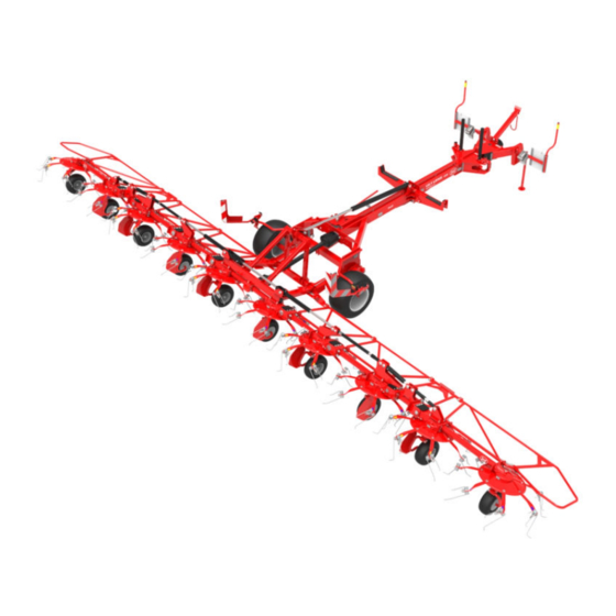
Page 9: Introduction
INTRODUCTION The Lely Lotus 1250 Profi is a pull-type rotary tedder-to ted mown fodder crops or to wide spread crop swaths. The working width of the Lotus is 12.50 m (41.01 ft), and can be driven up to 15 km/h. The wheels are positioned closely behind the tines to follow ground contours accurately. - Page 10 1. Primary PTO shaft - 2. PTO-support - 3. Front safety guard - 4. Wheel wedge - 5. Drawbar - 6. Hydraulic ram - 7. Secundary PTO shaft - 8. Transport wheel - 9. Lighting set - 10. Rear safety guard - 11. Safety brackets - 12. Tine - 13.
-
Page 11: Optional Extras
Optional extras 1.1.1 Spare Rotor Wheel The spare wheel support is installed on the Lotus to carry a spare wheel. So that a flat tyre can be mended quickly in the field. 1. Spare rotor wheel Figure 3. Spare Rotor Wheel Introduction... - Page 12 Introduction...
-
Page 13: Safety
SAFETY This chapter contains safety instructions you must obey when you use or do maintenance on your Lely Lotus. It also explains the safety decals on the Lely Lotus. Signal words Note the use of the signal words DANGER, WARNING and CAUTION. The... - Page 14 • Depressurise the hydraulic system before you connect or disconnect hydraulic hoses. • Use protective clothing, safety shoes, gloves, safety glasses and ear protectors, if necessary. • Clean or replace the safety decals regularly so that they can be read at all times.
-
Page 15: Explanation Of The Safety Decals
Explanation of the safety decals Caution: Read manual Read the operator's manual carefully before you operate the Lotus Danger: Moving parts Keep away from all moving parts unless they are locked and cannot move. Danger: Flying objects Keep a safe distance from the Lotus when the tractor engine is on. -
Page 16: Position Of The Safety Decals
Position of the safety decals Figure 4. Position of the Safety Decals Safety... -
Page 17: Operation
OPERATION Hydraulic control panel Read the tractor manual for the correct procedures to operate the tractor Note: hydraulics. The operator switches the handle(s) or moves the joystick to operate the Lotus. The following positions of the switches or joystick enable an action to the hydraulic system: •... - Page 18 The two hydraulic operations (forward/reverse) are depending on how the CAUTION connections are made to the tractor. • Hydraulic system (I) The blue marked hydraulic system (I) operates the following functions: • the operation to fold the frame supports with rotors in or out between the following position: - the position after operating the hydraulic system II, - headland position,...
-
Page 19: Connect The Lotus To The Tractor
Connect the Lotus to the tractor Procedure Ensure the towing vehicle has sufficient capacity to tow the trailer. Do not exceed the maximum hitch load DANGER Make sure the tractor is aligned with the Lotus. Reverse the tractor to the Lotus headstock. Make sure the three-point hitch arms of the tractor are at an equal height. - Page 20 1. Locking pin - 2. Parking jacks Figure 7. Link the Lotus to the tractor Operation...
- Page 21 1. Wheel wedges Figure 8. Wheel wedges storage position Operation...
-
Page 22: Disconnect The Lotus From The Tractor
Disconnect the Lotus from the tractor Always position the tractor on solid ground before you disconnect the WARNING Lotus from the tractor. Make sure there are no persons near the Lotus when you disconnect it from the tractor. The Lotus can be disconnected from the tractor in the transport position and Note: in the working position. -
Page 23: Move The Lotus From The Transport Position To The Working Position
Move the Lotus from the transport position to the working position Make sure there are no persons in the area when you move the Lotus to the headland position. Make sure the safety guards are moved to the bottom position. Safety CAUTION guards in top position cause damage to the Lotus when moving from transport position to the working position. - Page 24 A. Hydraulic system (II) - B.Hydraulic system (I) - C. Hydraulic (I) to the working position Figure 10. Move the Lotus to the Working Position Operation...
-
Page 25: Move The Lotus From The Working Position To The Transport Position
Move the Lotus from the Working position to the Transport Position Make sure the front axle weight of the tractor is sufficient (use front WARNING weights if necessary) and that you do not exceed the permitted axle load when the Lotus is in the transport position. Make sure the PTO shaft is not engaged when the Lotus is in the transport position. - Page 26 A. Hydraulic (I) from the working position - B.Hydraulic (I) - C. Hydraulic (II) Figure 11. Move the Lotus to the Transport Position A. Bottom position - B. Top position Figure 12. Move the Safety Guard to the Top Position 3-10 Operation...
-
Page 27: Start Tedding
Start Tedding Make sure no persons are near the Lotus when you engage the PTO. WARNING Make sure no persons are within a 25 meter radius of the Lotus during operation. Always switch off the tractor engine before you leave the tractor cab. Do not operate the Lotus without safety guards or covers, or if the safety guards or covers are damaged. - Page 28 Set the tractor hydraulic system to the floating position to lower the rotors to the ground so the Lotus will follow the contour line of the land during operation. If necessary, stop the tractor, disengage the tractor PTO and: Adjust the tines (page 4‑1). Adjust the height of the rotor wheels (page 4‑2).
-
Page 29: Move The Lotus From The Working Position To The Headland Position
Move the Lotus from the working position to the headland position Procedure Operate the tractor hydraulic system to lift the tedder to the headland position. The headland position lifts the rotors from the ground, so it is possible: Make sure you will not manoeuvre yourself in a dangerously position WARNING when performing adjustments or maintenance. - Page 30 3-14 Operation...
-
Page 31: Operation Adjustments
OPERATION ADJUSTMENTS Make sure that the PTO shaft is disengaged and the tractor engine is WARNING switched off before adjustments are made. Adjust the Tines Procedure Push the lock (1) down to disengage the lock and move the tine (2) to the required position (Figure 14, page 4‑1). -
Page 32: Adjust The Height Of The Rotor Wheels
Adjust the Height of the Rotor Wheels Procedure Move the Lotus to the headland position (page 3‑13). Switch off the tractor engine. Make sure the rotors can not move downwards. Remove the pin from the wheel assembly. Adjust the wheel assembly to the required height (Figure 15, page 4‑ 2) position: •... -
Page 33: Adjust The Rotor Angle
Adjust the Rotor Angle Procedure Make sure: The Lotus is connected to the tractor (page 3‑3). The Lotus is in the working position (page 3‑7). The hydraulic system is set to the floating position. The rotor wheels are set to the required position. Make sure the height adjustment of the tines is not too low. - Page 34 A. 25 cm (10 in) Figure 17. The distance over which the tines should touch the ground. Operation adjustments...
-
Page 35: Maintenance
MAINTENANCE Scheduled maintenance 5.1.1 Maintenance after operation • Clean the Lotus (page 5‑4). • Make sure the tines and tine arms are tight and not damaged. • Apply anti-corrosion agent to the bare metal parts. 5.1.2 Maintenance every 10 working hours •... -
Page 36: Maintenance Every 6 Year
5.1.6 Maintenance Every 6 Year • Replace all hydraulic hoses six years after their production date. Refer to the text on the hoses for their production date. 5.1.7 Maintenance before prolonged storage • Apply anti-corrosion agent to the bare metal parts. •... -
Page 37: Maintenance After Prolonged Storage
5.1.8 Maintenance after prolonged storage • Grease the PTO shafts (page 5‑7). • Replace the gearbox oil. • Grease the pivot points (page 5‑6). • Grease the drive line (page 5‑5). • Grease the bearings of the transport wheel axles. •... -
Page 38: Preventive Maintenance
Preventive maintenance Make sure that the PTO shaft is disengaged and the tractor engine is WARNING switched off before maintenance is made. 5.2.1 Clean the Lotus Procedure Make sure the Lotus is in the working position. Use a water jet to thoroughly clean the Lotus. Move the Lotus to the headland position (page 3‑13). -
Page 39: Grease The Drive Line
5.2.2 Grease the Drive Line Requirements: • Grease pump • Biodegradable grease (Total Biomultis SEP2 or equivalent) Procedure Grease the drive line on both sides with the grease pump. A = Grease after 10 hours. B = Grease after 40 hours. 1. -
Page 40: Grease The Pivot Points
5.2.3 Grease the pivot points Requirements: • Grease pump • Biodegradable grease (Total Biomultis SEP2 or equivalent) Procedure: Grease the pivot points with the grease pump. A = Grease after 40 hours. 1. Safety guard 2. Wheel frame 3. Head stock pin 4. -
Page 41: Grease The Pto Shaft
5.2.4 Grease the PTO shaft Requirements: • Grease pump with flexible hose. • Biodegradable grease (Total Biomultis SEP2 or equivalent) Refer to the third party documentation for detailed information to grease the CAUTION type of PTO shaft. The important grease point for all the type of PTO-shafts are described in the next procedure. - Page 42 1. PTO shaft 9-1154-0253-1 (Figure 22, page 5‑9) 2. PTO shaft 9-1154-0283-3 (Figure 23, page 5‑9) 3. PTO shaft 9-1154-0326-0 (Figure 24, page 5‑10) Figure 21. Grease point PTO shafts Maintenance...
- Page 43 Type PTO 100. h. 100. h. n.a.. A. Grease nipple - B. Guard bearing - C.Profiled tube Figure 22. Grease Points PTO Shaft (Type W) Type PTO W (P-sealing) 250. h. 100 h. 100 h. A. Grease nipple - B. Guard bearings - C. Grease nipple Figure 23.
- Page 44 Type PTO 100. h. 100. h. n.a.. A. Grease nipple - B. Guard bearing - C.Profiled tube Figure 24. Grease Points PTO Shaft (Type W) 5-10 Maintenance...
-
Page 45: Replace The Gearbox Grease
5.2.5 Replace the Gearbox Grease Requirements: • Shell Gadus S2 V220-AC0 • Loctite 243 • Loctite 574 Procedure Remove the hose clamp (2) and the protection cover (1). Remove the bolts (4) and cover (3). Remove the old grease from the gearbox . Fill the gearbox with 1.2 kg of grease. -
Page 46: Corrective Maintenance
Corrective maintenance Make sure that the PTO shaft is disengaged and the tractor engine is WARNING switched off before maintenance is made. 5.3.1 Replace the Tine(s) Purpose This procedure tells you how to replace the tines, which are liable to wear or can break by an excessive load. -
Page 47: Adjust The Deflection Of The Rotors
5.3.2 Adjust the Deflection of the Rotors Procedure Park the Lotus on a level floor. Place an elevation of approximately 4 cm (1.57 in) under the four central rotor wheels. Move the Lotus to the working position (page 3‑7). Make sure the Lotus is level. Verify the adjustment of the deflection points on the adjustment-bar on both sides of the Lotus: Unlock the locking-nut to release the tension on the adjustment-... - Page 48 1. Adjustment-bar - 2. Counter nut - 3. Stop bolt - 4. Deflection point - A. 4 cm (1.57 in) Figure 27. Adjust the Deflection of the Rotors 5-14 Maintenance...
-
Page 49: Diagrams And Tables
DIAGRAMS AND TABLES Diagrams and Schematics 1a. Single-acting ram (transport position) - 1b. Single-acting ram (headland position) - 2. Single-acting bar - 3. Double-acting ram - 4. Single-acting bar - 5. Double-acting ram - 6. Single-acting ram - (P/T). Blue marked hydraulic hose - B (P/T). -
Page 50: Bolt And Nut Torque Table
Bolt and nut torque table The following tables specify the standard torque load for all quality bolts on the Lotus. Always use a calibrated torque wrench when you torque-tighten bolts and nuts. Thread size Bolt quality Nut quality 13.5 21.5 41.0 71.0 Thread size... -
Page 51: Tyre Pressure Diagram
Tyre Pressure Diagram A. 100 kPa (1.0 bar) - B. 150 kPa (1.5 bar) - C. 275 kPa (2.75 bar) - D. 300 kPa (3.0 bar) Figure 29. Tyre Pressure Diagram Diagrams and tables... - Page 52 Diagrams and tables...
-
Page 53: Specifications
SPECIFICATIONS The specifications of the Lotus are defined in the following table: Working width 12.50 m (41.01 ft) Transport width 2.98 m (9.77 ft) Transport height 2.95 m (9.68 ft) Transport length 6.50 m (21.32 ft) Approximate tedding angle 10º - 17º Number of rotors Number of tines per rotor 7 double tines... - Page 54 Specifications...
- Page 55 INTENTIONALLY BLANK...
- Page 56 LELY INDUSTRIES NV Weverskade 110 NL-3147 PA Maassluis Tel +31 (0)10 - 59 96 333 Fax +31 (0)10 - 59 96 444 www.lely.com Live Life Lely...
Need help?
Do you have a question about the 1250 PROFI and is the answer not in the manual?
Questions and answers