
Related Manuals for Vivax Metrotech vLocPro2


Summary of Contents for Vivax Metrotech vLocPro2
- Page 1 Series 2 User Handbook (vLocPro2, vLocML2) (English Edition) Version 1.8 P/N: 4.04.000021 vLocPro2 Receiver Serial Number above 20401082961 vLocML2 Receiver Serial Number above 21101080928...
-
Page 3: Table Of Contents
Service & Support............................5 Serial Number and Software Revision Number................5 Distributors and Service Centers Closest to You:.................6 vLocPro2 Receiver.............................7 vLocPro2 Receiver........................7 Charging the Receiver Batteries....................8 vLocPro2 Receiver Main Display....................9 vLocPro2 Receiver Screen Shots....................10 Locating Mode (Response)......................11 3.5.1 Peak Response Mode......................11 3.5.2 Broad Peak Mode......................11... - Page 4 Data Logging............................23 Bluetooth............................23 5.1.1 Fitting the Bluetooth Module....................23 Holux GPS Device Overview......................24 5.2.1 Pairing with the vLocPro2/vLocML2 Receivers..............25 5.2.2 Gathering Data in Active Modes..................25 5.2.3 Gathering Data in Power and Radio (Passive) Modes.............25 5.2.4 Transferring Data from the Locator to a Computer............26 Trimble ProXT/XH........................26...
- Page 5 Induction Mode.........................56 Direct Connection Mode......................57 Clamp Mode.........................57 Loc-1Tx Transmitter......................58 Pushbuttons..........................58 External Connectors........................58 Replacing Alkaline Batteries.......................58 Rechargeable Batteries......................59 Loc-1Tx Transmitter Operation....................59 Using the vLocPro2..........................60 Using the Receiver........................60 9.1.1 Line Locating........................60 9.1.2 Depth & Current Measurement..................60 9.1.3 Sonde Location........................61 9.1.4 Using the Compass (line direction indicator) Feature to Locate Sondes......62 Passive or Active Location......................63...
- Page 6 9.2.2 Active Locating.........................64 Applying the Transmitter’s Signal....................64 9.3.1 Direct Connection......................64 9.3.2 Clamp (Coupler).......................65 9.3.3 Induction...........................66 Searching (sweeping) an Area....................67 Tracing a Buried Line.........................67 9.5.1 Pinpointing & Confirming the Buried Line.................68 9.5.2 Distorted Fields........................68 Measuring Depth and Current....................69 Signal Direction Precision Identification..................71 Using the Accessories.......................73 9.8.1 Using the LPC Separation Filter..................73...
-
Page 7: General Safety & Care Information
General Safety & Care Information General Safety & Care Information Who Can Use This Equipment • This equipment must only be used by people suitably trained in the use of pipe and cable locators. Work-site Safety • Use your companies, or other applicable safety codes and rules when using this equipment. •... -
Page 8: Lithium-Ion Batteries (Rechargeable)
General Safety & Care Information & current rating will not have the same control circuitry and can cause damage to the product, overheating, and in extreme cases fire or harm to the individual. • Do not assume that if the plug fits, it is the correct charger – a charger with the correct part number must be used –... -
Page 9: Transportation Of Lithium-Ion And Lithium-Metal Batteries
General Safety & Care Information 1.4.6 Transportation of Lithium-Ion and Lithium-Metal Batteries • The Lithium-Ion and Lithium-Metal batteries used in Vivax-Metrotech products meet the required safety standards and include the designated protection circuitry. • Recent regulation changes require that when batteries with Lithium-Ion and Lithium-Metal batteries are transported, the packaging must include specified warning labels. -
Page 10: American & Canadian Safety Notices
General Safety & Care Information American & Canadian Safety Notices • This transmitter and receiver comply with the general conditions of operation, pursuant to part 15 of the FCC Rules. ○ CFR 47 Part 2 ○ CFR 47 Part 15 •... -
Page 11: Service & Support
Service & Support Service & Support Serial Number and Software Revision Number Always quote your receiver and transmitter model number, serial number and software revision number when requesting product support. They can be found as follows: (for reference only) Model & Serial Number NOTE The transmitter Model &... -
Page 12: Distributors And Service Centers Closest To You
Service & Support Distributors and Service Centers Closest to You: World Headquarters, United State of America China Vivax-Metrotech Corporation Leidi Utility Supply ( Shanghai) Ltd. 3251 Olcott Street, No. 780, Tianshan Rd, Santa Clara, CA 95054, USA Shanghai, China 200051 Website : www.vivax-metrotech.com T/Free : 4006-206-719... -
Page 13: Vlocpro2 Receiver
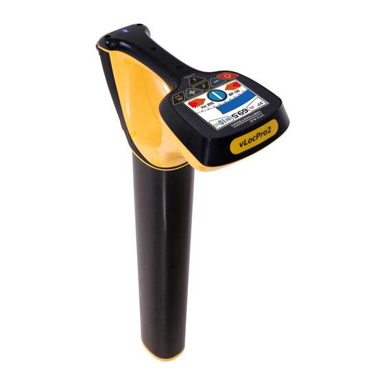
Receiver vLocPro2 Receiver vLocPro2 Receiver The vLocPro2 is a Precision Location System designed to meet the needs of Utility Companies and their contractors. The following describes the features and use of the receiver: Charging Socket Optional Bluetooth Module Mini USB Port Data Transfer and Pushbutton &... -
Page 14: Charging The Receiver Batteries
Receiver Charging the Receiver Batteries The vLoc series 2 can be used with either alkaline batteries or it can be supplied with an interchangeable rechargeable battery pack. When alkaline battery is used, Icon A will appear on the screen. When the rechargeable battery pack is used, Icon B will be displayed. -
Page 15: Vlocpro2 Receiver Main Display
Receiver vLocPro2 Receiver Main Display The vLocPro2 has several display options – the display shown below is representative of the types of display and icons used. Frequency Select Digital Display of Signal Response Loudspeaker Status Gain Control (reduce gain) -
Page 16: Vlocpro2 Receiver Screen Shots
Main Display Main Menu The vLocPro2 is a Precision Location System designed to meet the needs of Utility Companies and their contractors. The following describes the features and use of the receiver. Page 10 of 90... -
Page 17: Locating Mode (Response)
Receiver Locating Mode (Response) The vLocPro2 receiver has four antennas, and these can be toggled through different configurations (modes) to provide different responses to the signals radiating from the buried pipes and cables. The modes are: 3.5.1 Peak Response Mode... -
Page 18: Null Mode
Receiver 3.5.3 Null Mode Compass (line direction indicator) This uses vertical antennas, and provides a minimum or “Null” response over the center of the radiated signal from the buried line. The compass (line direction indicator) shows the direction of the cable (available in Active modes). -
Page 19: Sonde Mode
Sonde when directly over it and the color of the compass (line direction indicator) change from clear to blue. The vLocPro2 receiver must be used in a different orientation when locating a Sonde – due to the way the signal from the Sonde radiates. -
Page 20: Audio
“-” pushbuttons increments/decrements the gain. Frequency Selection The vLocPro2 receiver is capable of locating a large number of frequencies or frequency combinations. A list of these frequencies can be accessed using the setup menu. Most of these frequencies listed – you will never use – the setup menu allows you to select the frequencies you wish to use regularly. -
Page 21: Information Pushbutton (Depth & Current)
Receiver To select the frequencies you wish to use regularly – enter the setup menu by pressing and holding the “i” pushbutton for 2 seconds. Use the “+” and “-” to select the word “Frequency” – then press the “M” pushbutton to display the list of available frequencies. -
Page 22: Information Pushbutton (Setup Menu)
Receiver 3.10 Information Pushbutton (Setup Menu) As described previously, a second function performed by the “i” is to access the setup menu. Press and hold the “i” pushbutton for two seconds to display the setup menu. Use the “+”, “-” to navigate through the various options and use the “M”... -
Page 23: Vlocml2 Receiver
vLocML2 Receiver vLocML2 Receiver Introduction The vLocML2 is a variant of the vLoc locator. It can be identified by the loop antenna attached to the base of the locator tube. The purpose of the loop antenna is to energize passive markers buried above non metallic services or points of interest. -
Page 24: Operating The Vlocml2
vLocML2 Receiver Pipeline paths, main stubs, service stubs, tees, road crossings, all types of valves, meter boxes, stopping fittings, depth changes, transition fittings, squeeze points, pressure control fittings, electro fusion couplings, all types of fittings and joints Gas (Yellow) Frequency: 83 kHz Gas and Electric Installations (EDF only) Frequency: 40 kHz EDF Power (Grey Disk) - Page 25 vLocML2 Receiver It is also possible to take depth to marker estimations in the dedicated mode. (Section 4.2.4) Use the “f” pushbutton to select the marker type that is to be located. Signal strength from Marker used for pinpointing position Marker detection ball (Not adjustable) Marker icon indicating marker detection active...
-
Page 26: Marker Depth Estimation In Dedicated Mode
vLocML2 Receiver 4.2.4 Marker Depth Estimation in Dedicated Mode It is only possible to undertake depth measurement of a marker, when in the dedicated mode. Procedure: 1. Switch to Dedicated mode. (ie. Ensure only marker icon is displayed in bottom left hand corner of the display) 2. -
Page 27: Dual Configuration
vLocML2 Receiver If the following display is shown, this indicates that the marker is either out of range or there is an invalid signal. 4.2.5 Dual Configuration In this configuration the unit can be used to trace an energized cable or pipe whilst simultaneously looking for the presence of markers. - Page 28 vLocML2 Receiver strength from the cable. Note that in the dual configuration mode the “+” and “-” pushbuttons alter the sensitivity of the cable locate bargraph. It is not necessary to alter the sensitivity to the marker locate function. The sound is from the line position. In dual configuration the marker has no sound associated with it.
-
Page 29: Data Logging
For more information on Data logging and GPS see section 5.2.5.4. Bluetooth As an optional extra the vLocPro2 and vLocML2 receivers can be fitted with a Bluetooth communications accessory. The Bluetooth option can be retrofitted and can be ordered at a later date if preferred. -
Page 30: Holux Gps Device Overview
It can either be mounted in the purpose designed holder from Vivax-Metrotech or can be positioned anywhere within a few meters from the vLocPro2. For instance using “Velcro” to attach it to the peak of a baseball cap ensures clear view of the sky and satellites. -
Page 31: Pairing With The Vlocpro2/Vlocml2 Receivers
3. Press the “+” button to scroll to “Bluetooth Pairing” and press the “M” pushbutton. The vLocPro2 will begin to search for available devices. At the end of the search, a list will be displayed which should include “HOLUX_M-1200” Use the “+” and “–” pushbuttons to highlight this device and press the “M”... -
Page 32: Transferring Data From The Locator To A Computer
5.2.4 Transferring Data from the Locator to a Computer To transfer data it is necessary to use the vLocPro2 Configurator Tool called MyLocator2. This is a simple program that can be downloaded from the Vivax-Metrotech web site at www.vivax- meterotech.com. The file can be found under the Support/Download Library/Others Download. - Page 33 Data Logging 1. From “Skyplot” select “Setup”. 2. Now select “GPS Settings”. 3. Select COM1 and set the parameters as below and then press OK. 4. Now select the spanner on the “NMEA Output” line. Page 27 of 90...
-
Page 34: Transferring Data From The Vloc2 To A Computer
Data Logging 5. Set the following parameters: 6. Press OK to save parameters to the GPS. 7. These parameters are suggested values. Experienced users may decide to alter them to suit the particular requirements of an application. 8. Pairing with the vLoc receiver is similar to the Holux described previously. Data gathering is also similar to the Holux procedure. -
Page 35: Splash Screen
Data Logging In its basic form it allows the operator to: • Check the software revision number and download the latest version. This feature is useful where software changes have been made to enhance existing features and to install new free of charge features as they become available. -
Page 36: Upload Data Files
Data Logging 2. The software will accept the following formats: JPEG, BMP, GIF, PNG, ICO. 3. Select the file and open. The screen below should now also contain a representation of the picture. 4. Press “Download” to transfer the file to the vLoc or “Clear” to remove the file. 5. -
Page 37: Software Update
Data Logging 4. When the upload is complete (Should only take a second or two) it will be possible to save the data. 5. Press the “Save As” button. 6. Browse your computer files to find the desired file location. Name the file and use the “Windows”... -
Page 38: Switch On/Off User Menu Settings
Data Logging The extra features available are: • Switch on or off user menu settings • Switch off frequency selections By doing this the locator is simplified and tailored exactly to the customer requirements. The configuration can be saved as a “configuration” file and used to configure other vLoc2 locators. -
Page 39: Switching On/Off Frequency Selections
Data Logging 5.4.8 Switching On/Off Frequency Selections 1. Click on the “Frequencies” tab. A screen similar to the one below should be shown. 2. Each row is color coded: a. Grey indicates that frequency is not selected for either the menu or the frequency key. b. -
Page 40: 5.4.10 Configuration Lock Dongle
Data Logging 5.4.10 Configuration Lock Dongle A Configuration Lock dongle is available that allows “lockout” of features and functions so that operators are forced to use particular settings. The dongle is also used to unlock these features. To activate the dongle, plug it into any USB socket on the host computer. With the dongle active, the MyLocator2 screen will look similar to the picture below. -
Page 41: 5.4.11 Icon Summary
Data Logging 7. Now click on the “Menu Settings” Tab 8. Uncheck the Frequency and all antenna modes except “Peak” as below. Note also the Locate Menu box is un-checked; this will prevent the function appearing in the user menu. 9. -
Page 42: Loc-10Tx Transmitter
Loc-10Tx Transmitter Loc-10Tx Transmitter Loc-10Tx Transmitter Overview The Loc-10Tx transmitter is a rugged portable transmitter powered by alkaline “D” cells or Ni-MH (Nickel Metal Hydride) rechargeable batteries. The following describes the features and uses of the transmitter. 6.1.1 Display 83.1 kHz 1 0 0 Frequency Being Transmitted Output Setting (Step) (filled box... -
Page 43: Information Pushbutton
Loc-10Tx Transmitter 6.1.3 Information Pushbutton Frequency Menu Multi Frequencies LCD Contrast Resistance Voltage Volume When the “i” (information) pushbutton is pressed, the display will show the volume level of the audio; use the “+” and “-” pushbuttons to increase/reduce the volume or turn the beeper off (off – low –... -
Page 44: Removing The Battery Tray
The battery condition (charge) is displayed on the left side of the display. “LP” letters appears when the battery charge becomes one bar. 6.2.1 Removing the Battery Tray Push up button Pull out bottom of catch Lift up catch until it clears catch plate 6.2.2 Replacing the Alkaline Battery... -
Page 45: Rechargeable Battery Pack Charging And Disposal
Loc-10Tx Transmitter Place top of catch over catch plate Push up button underneath the catch – where holding that up push in the bottom of the catch. You will hear a positive “click” (Do not force catches) WARNING Power “IN” socket Two pins are used for power in from charger (to charge rechargeable batteries). -
Page 46: Direct Connection Mode
Loc-10Tx Transmitter “Induction” mode is generally used when no access is available to make a direct connection, or a clamp connection. When using induction, it is very likely that the signal being induced onto the target line will also be induced onto other lines in the area, and onto above ground features such as wire fences. -
Page 47: Clamp Mode
Loc-10Tx Transmitter Wherever a direct connection can be safely made without the risk of injury, damage to customer’s plant, or the transmitter, it is the best way of applying the transmitter’s signal. The coupling of the transmitted signal to other pipes and cables in the area will be much less than with induction, although where commonly bonded systems are encountered –... -
Page 48: Frequencies
Loc-10Tx Transmitter The clamp is a specialized inductive device (sometimes known as a toroid or coupler). All clamps are optimized to work at specific frequencies. In most cases clamps are designed to be used at frequencies generally between 8 kHz and 83 kHz. The transmitter will only allow the selection of a suitable range of frequencies for your clamp. -
Page 49: Most Used Frequencies (Frequency Selection) Feature
Loc-10Tx Transmitter As with most manufacturers the clamps and induction antennas are tuned to specific frequencies, and do not work over the complete range of frequencies. Frequencies are selected by pressing the “f” pushbutton which toggles through the available frequencies for the selection mode. The frequency is automatically selected if you don’t toggle past it within two seconds. -
Page 50: Multi Frequency Mode For Direct Connection
Loc-10Tx Transmitter In SD mode, In Clamp mode, 2. Screen will show a list of frequencies available, with the central one in a box. 3. Pressing the "+" or "-" pushbuttons, you can scroll up or down through the available frequencies. - Page 51 Loc-10Tx Transmitter NOTE • When using multi frequency mode, total power will be split between the activated frequencies. • The frequencies have to be available in the main menu. To enter the "Multi Freq. Setup" menu, proceeds as follows: 1. Press "i" pushbutton five times to get to the "Multi Frequency" screen and press “f” pushbutton to activate the multi frequency mode.
-
Page 52: Loc-5Tx Transmitter
Loc-5STx Transmitter Loc-5STx Transmitter Loc-5STx Transmitter Overview The Loc-5STx transmitter is a rugged portable transmitter powered by alkaline “D” cells or Li-Ion rechargeable batteries. The following describes the features and uses of the transmitter. Pushbutton controls LCD Display Single Output Connection (Loc-5STx) Blanking Plate Piezo beeper Battery compartment... -
Page 53: Pushbuttons
Loc-5STx Transmitter External Voltage Warning The transmitter checks the line when connected. If the line is carrying voltages in excess of 25V, it will display the “high voltage” warning icon, and not allow the transmitter to operate. In addition, the transmitter is protected in the event of excessive voltage or voltage spikes on the line. 7.1.2 Pushbuttons On/Off... -
Page 54: Removing The Battery Tray
Loc-5STx Transmitter 7.2.1 Removing the Battery Tray 7.2.2 Replacing the Alkaline Battery • To access batteries – undo the two latches that are locking the battery cover • To remove batteries – remove the battery holder from the inside of the unit •... -
Page 55: Rechargeable Battery Pack Charging And Disposal
Loc-5STx Transmitter 7.2.5 Rechargeable Battery Pack Charging and Disposal Follow the instructions in the General Safety & Care section portion of this document. Only use the battery charger supplied with the battery. Using a non-approved charger may damage the battery pack and could cause overheating. The rechargeable battery pack must be connected to the transmitter in order to charge. -
Page 56: Direct Connection Mode
Loc-5STx Transmitter All the frequencies in favorite frequencies mode that are higher than 8 kHz can be selected by pressing “f” pushbutton in main display. Multiple induction frequencies are available based on the user selection. See section 7.4.2 for adding and removing frequency from the favorite frequencies list. -
Page 57: Clamp Mode
Loc-5STx Transmitter but frequencies over 45 kHz are restricted to 1 watt. Using direct connection and the higher power at the low frequencies helps significantly in achieving greater location distances. Direct connections should not be made to cables carrying greater than 25V (or as your safety practices allow). - Page 58 Loc-5STx Transmitter • 640Hz (where electrical systems are 50Hz) direct connection – 5 watts. • 8 kHz direct connection – 5 watt. • 33 kHz direct connection – 5watt. • 65 kHz direct connection – 1 watt. • 83.1 kHz, 131 kHz direct connection – 1 watt (depending on region). •...
-
Page 59: Most Used Frequencies (Frequency Selection) Featur
Loc-5STx Transmitter feature – in most circumstances this output level is sufficient. Increasing the output power unnecessarily will reduce the battery life unnecessarily. All other settings remain the same as the last setting used. 7.4.2 Most Used Frequencies (Frequency Selection) Feature This feature can be used to allow operator to choose his most used frequencies from a list of possible frequencies. -
Page 60: Multi Frequency Mode For Direct Connection
Loc-5STx Transmitter 2. Screen will show a list of frequencies available, with the central one in a box. 3. Pressing the " " or " " pushbuttons, you can scroll up or down through the available frequencies. 4. Once the wanted frequency is inside the box, press “f” pushbutton to select or deselect the frequency. -
Page 61: Transmitter Battery
Loc-5STx Transmitter Press the " " and " " pushbuttons to scroll through the available frequencies, and bring the wanted one in the first box. Press "f" pushbutton to move the box down and the " " and " " pushbuttons to select the second frequency. -
Page 62: Battery Charging And Disposal
Loc-5STx Transmitter WARNING Use only Vivax-Metrotech recommended charger. WARNING Charging socket Two pins are used for power in from charger (to charge rechargeable batteries). NOTE Rechargeable pack cannot be charged from a 12V DC source. Contact Vivax-Metrotech or a Vivax-Metrotech approved service center for wiring diagram of plug, if attempting to repair any of the “charging”... -
Page 63: Direct Connection Mode
Loc-5STx Transmitter “Induction” mode is generally used when no access is available to make a direct connection, or a clamp connection. When using induction it is very likely that the signal being induced onto the target line will also be induced onto other lines in the area, and onto above ground features such as wire fences. -
Page 64: Loc-1Tx Transmitter
Loc-1Tx Transmitter Loc-1Tx Transmitter Pushbuttons On/Off Control Frequency Select (the arrow points to the corresponding frequency printed on the label on top) Output High/Low setting Audio Beeper Level External Connectors Mini USB Port Output Fuse Speaker Output Connection DC Input (power supply only) ¼... -
Page 65: Rechargeable Batteries
Loc-1Tx Transmitter WARNING Alkaline Batteries – insert alkaline batteries (x4) as shown Rechargeable Batteries Rechargeable batteries are not available for the Loc-1Tx transmitter. Loc-1Tx Transmitter Operation The operation of the Loc-1Tx transmitter is very similar to the Loc-5Tx transmitter. This is covered in section 7.7 to 7.9. -
Page 66: Using The Vlocpro2
Using the vLocPro2 Using the vLocPro2 Using the Receiver 9.1.1 Line Locating Line locating is when a pipe or cable is being located. When line locating, the receiver should be held with the display forward, and then sweep to the left and right across the suspected direction of the buried line. -
Page 67: Sonde Location
Using the vLocPro2 DEPTH • Once the position and direction of the cable has been established, stand with the base of the locator on the ground – with the locator in the absolute “Peak” position (over and in line). Then press the “i” information pushbutton briefly, the current and depth will be displayed. -
Page 68: Using The Compass (Line Direction Indicator) Feature To Locate Sondes
Using the vLocPro2 9.1.4 Using the Compass (line direction indicator) Feature to Locate Sondes Switch on the vLocCam. Select the frequency to match the Sonde frequency. Use the mode pushbutton to select Sonde. Stand in the approximate vicinity of the Sonde. Press the “+” pushbutton to increase the gain so that a steady bar graph reading is displayed. -
Page 69: Passive Or Active Location
Using the vLocPro2 Using the compass (line direction indicator) to locate the Sonde requires free space to walk to the side of the Sonde. If there is an obstacle such as a wall or vehicle that restricts walking in an arc, the following method can be used. -
Page 70: Active Locating
Using the vLocPro2 Passive location is used to search an area to see if buried metallic lines are present (known as locating to AVOID). It does not help to identify what buried pipe or cable is present, only to confirm that there is a pipe or cable there. -
Page 71: Clamp (Coupler)
Using the vLocPro2 WARNING Never make a direct connection to live cables carrying hazardous voltages. Do not plug the connection leads into the transmitter before connecting to the buried line and fixing the ground stake. Take the ground stake and push firmly into the ground and connect it to the black connection lead. -
Page 72: Induction
Using the vLocPro2 Do not plug the clamp into the transmitter before applying it to the target line. Open the jaws of the clamp, place around the target line, close the jaws. Be sure that the jaws of the clamp are completely closed. -
Page 73: Searching (Sweeping) An Area
Using the vLocPro2 When using the “Induction” mode to apply a signal to a line, ensure that a minimum distance of 50ft (15m) is maintained. This is because the transmitter will transmit signal through the air which will interfere with signals from the cable, resulting incorrect information. -
Page 74: Pinpointing & Confirming The Buried Line
Using the vLocPro2 9.5.1 Pinpointing & Confirming the Buried Line Marking the exact position of the buried line is generally called pinpointing. Pinpoint the line before marking its position. Place the receiver in “Peak” or “Left/Right” mode, pass the blade of the receiver across path of the cable and identify the peak response on the display and/or audibly. -
Page 75: Measuring Depth And Current
Using the vLocPro2 • Measure the depth of the buried line by pressing “i” pushbutton briefly to measure depth and current. The depth should be approximately in line with the “as built” plans available. If no plans are available logic would still help to assess the situation (if you are looking for a CCTV distribution cable and the depth indicated is 5ft (1.5m) it is probably not your cable). - Page 76 Using the vLocPro2 Distance A to B = Depth (D) Distance (A’ to B’)/2 = Depth (D) Semi Automatic Triangulation Mode On some models a "triangulation mode" is available that assist in taking these types of measurements. To use the Triangulation mode the function must first be activated in the User Menu. The User Menu will give the option of Peak Depth or Triangulation.
-
Page 77: Signal Direction Precision Identification
9.7 Signal Direction Precision Identification (Available for vLocPro2-SD and vLocML2 models only) Some models in the vLoc series of locators contain a feature called “SIGNAL DIRECTION”. This feature is used to verify if the line being located is the target to which the transmitter has been connected. - Page 78 Using the vLocPro2 ○ SD-USA – if in North America or any territory where the power system is 60Hz. ○ SD-EUR – if in Europe or any territory where the power system is 50Hz. • The receiver may, or may not be flashing the “SD” icon and compass (line direction indicator) bezel.
- Page 79 Using the vLocPro2 • Re-trace your line back to a point where a solid signal direction is obtained. Precisely pinpoint the line and stand with your back to the direction of the transmitter as you did when you initiated the original sync, and press the “i” pushbutton then the enter/return pushbutton to re-sync with the transmitter signal.
-
Page 80: Using The Accessories
Using the vLocPro2 Using the Accessories 9.8.1 Using the LPC Separation Filter The LPC separation filter (LPC) is used to safely inject a trace tone to a live cable via a domestic mains socket, so that the cable can be traced from the premises to the connection in the street. It is suitable for connecting to voltages between 100V AC and 250V AC. - Page 81 This will ensure that the ground fault is not masked by deliberate bonding to ground. The A-frame cannot distinguish between these two situations. After isolating the line, use the vLocPro2 transmitter resistance measuring function, or a dedicated resistance measuring device to confirm that there is a fault to ground. The A-frame will typically detect faults up to two Mohm and above (depending on the distance from transmitter, soil conditions etc).
- Page 82 Using the vLocPro2 Remove the plastic spike covers from the A-frame. Walk along the route of the line placing the spikes of the A-frame in the ground (with the green leg pointing away from the transmitter connection point) every two or three paces. If starting near the transmitter, the arrow on the display will point away from the ground point.
-
Page 83: Using The Analogue Remote Antenna
Using the vLocPro2 9.8.3 Using the Analogue Remote Antenna The remote stethoscope antenna can be used to help identify a particular cable on a cable tray or where cables are bunched together. Methods: 1. Connect a signal to the cable to be identified. The remote stethoscope functions has an operational frequency range of 512Hz up to 200 kHz, but low frequencies should be a preference in this application as they are less likely to leak or bleed over to other cables. - Page 84 Using the vLocPro2 6. Connect the remote stethoscope antenna to the accessory input of the receiver. The correct settings and user interface will be automatically selected. 7. Ensure the frequency selected on the vLoc is the same as selected on the transmitter.
- Page 85 3. At the point of interest, run the remote stethoscope antenna along the suspected target cable. If the correct cable is being assessed the signal will increase and decrease in sympathy with the twist of the two conductors within the cable. 4.
- Page 86 2. Select an SD signal from the transmitter (either SD-USA or SD-EUR). 3. Connect the remote antenna accessory to the locator and place it on the red lead of the transmitter with the arrow pointing away from the transmitter. Select the frequency using the “f” button so that it matches the selection on the transmitter.
- Page 87 The system is now ready to identify the cable at the location of the interest. Identifying a cable Having confirmed the antenna is synchronized with the receiver, proceed to the location the cable is to be identified. Place the antenna on each of the suspected cable in turn ensuring the correct orientation, ie the arrow on the antenna pointing away from the transmitter.
- Page 88 WARNING The remote stethoscope antenna is a useful tool to help identify cables. However, it should not be used as positive identification before an unused cable is cut. Always follow company procedures when cutting disused or isolated cables. Page 82 of 90...
-
Page 89: Accessories & Options
Accessories & Options Accessories & Options 10.1 A-frame (Optional) The A-frame accessory is used to detect ground faults on pipes and cables. In the case of pipes, the faults consist of coating defects. In the case of cables, faults are usually caused by insulation damage allowing the metallic sheath (or internal conductor) to become in contact with the ground. -
Page 90: Lpc Separation Filter (Optional)
Accessories & Options 10.5 LPC Separation Filter (Optional) The LPC separation filter (LPC) is used to safely inject a trace tone to a live cable via a domestic mains socket, so that the cable can be traced from the premises to the connection in the street. -
Page 91: Clamp (Optional)
Accessories & Options D64-09-LR61 Sonde 2.5in (64mm) x 7.3in (186mm) long, • 9.8 kHz, range 26ft (8m) . • 1 x LR61 battery. D64-83-LR61 Sonde • 2.5in (64mm) x 7.3in (186mm) long, 83 kHz, range 26ft (8m) . • 1 x LR61 battery. D23F-512-AA / D23F-640-AA Sonde •... -
Page 92: Lithium-Ion Rechargeable Battery Pack (Standard)
Accessories & Options To operate the clamp jaws when attached to the rod, gently pull on the clamp cord which will open the jaws. Release to cable to close them. 10.10 Lithium-ion Rechargeable Battery Pack (Standard) The Lithium-ion rechargeable battery pack is supplied as standard. -
Page 93: Ground Spool (Optional)
Accessories & Options 10.17 Ground Spool (Optional) Used to extend the ground connection to a suitable grounding position. 10.18 Banana Plugs Adapter (Optional) Adapts the direct connection crocodile clip to banana plug allowing the direct connection leads to be connected to a banana socket. -
Page 94: 10.23 Loc-10Tx Alkaline Battery Tray
10.23 Loc-10Tx Alkaline Battery Tray Requires 12 x Alkaline D cells. 10.24 Live Plug Connector (LCC) For use on live cables up to 480V AC 60/50Hz. Operating frequencies: 8.192k Hz, 32.768k Hz, 8.44k Hz SIS. For best results, connect across a phase cable and independent ground. Page 88 of 90... -
Page 95: Glossary
Glossary Glossary Active Locate A locate where a transmitter is used to apply a signal to a buried pipe or cable, the position of which is then located by a receiver tuned to the same frequency. Active Signal A signal applied by the locator transmitter to a buried line. Typical this is a very precise frequency. - Page 96 Glossary Peak A maximum response to a buried line. Pinpoint Using a receiver to identify the exact position of a buried line. Response The indication that the receiver gives which is caused by the signals it is receiving. This can be visual, audio or both. Typically it is displayed on the locators dot matrix display and audibly from a loudspeaker in the receiver housing.
- Page 97 Notes: Vivax-Metrotech Corporation, 3251 Olcott St.,Santa Clara CA 95054, USA Website: www.vivax-metrotech.com...
Need help?
Do you have a question about the vLocPro2 and is the answer not in the manual?
Questions and answers