MGE UPS Systems Galaxy 3000 Installation And User Manual
10-30kva uninterruptible power systems
Hide thumbs
Also See for Galaxy 3000:
- Installatie en gebruikershandleiding (56 pages) ,
- Installation and user manual (172 pages) ,
- Erratum of installation and user manual (4 pages)

Related Manuals for MGE UPS Systems Galaxy 3000


Summary of Contents for MGE UPS Systems Galaxy 3000
- Page 1 . m g e u p s . c o m Galaxy 3000 10-30kVA Uninterruptible Power Systems Installation and User Manual...
-
Page 2: Revision History
Galaxy 3000 10-30kVA Galaxy 3000 10-30kVA Installation and User Manual Revision History Galaxy 3000 10-3-kVA UPS Installation and User Manual Revision: Initial Release 05/01 ECN 002152 08/01 ECN 002271 10/01 ECN 002473 03/02 ECN 002565 02/03 ECN 003280 05/03 ECN 003507... -
Page 3: Table Of Contents
Getting Started with Galaxy 3000 ........QS—1... - Page 4 Galaxy 3000 10-30kVA Section 2 Setup and Installation Scope ..........2 — 1 Electrical Specifications .
- Page 5 Installation and User Manual Section 4 Maintenance Scope ..........4 —1 Servicing Batteries .
- Page 6 Footprints for Galaxy 3000........1 —...
-
Page 7: Important Safety Instructions
Installation and User Manual IMPORTANT SAFETY INSTRUCTIONS SAVE THESE INSTRUCTIONS – This manual contains important instructions for Galaxy 4000 that must be followed during operation and maintenance of the equipment. WARNING Opening enclosures expose hazardous voltages. Always refer service to qualified personnel only. - Page 8 Galaxy 3000 10-30kVA WARNING HIGH LEAKAGE CURRENT. Earth connection essential before connecting supply. ATTENTION COURANT DE FUITE ELEVE. Raccordement a la terre indispensable avant le raccordement au reseau. WARNUNG! Hoher Ableitstrom Vor Inbetriebnahme Schutzleiterverbindung herstellen. Certification Standards - Three Phase UPS ◗...
-
Page 9: Safety Of Persons
Installation and User Manual Safety of Persons ◗ The UPS has its own internal power source (the battery). Consequently, the power terminals may be energized even if the UPS is disconnected from the AC power source. ◗ The UPS must be properly grounded. ◗... -
Page 10: Caution: Record All Serial Numbers
Galaxy 3000 10-30kVA CAUTION: Record All Serial Numbers! RECORD ALL SERIAL NUMBERS FOR THE GALAXY 3000 AND ACCESSORIES. THESE SERIAL NUMBERS WILL BE REQUIRED IF YOUR SYSTEM NEEDS SERVICE. KEEP THIS MANUAL IN A PLACE WHERE YOU CAN REFERENCE THE SERIAL... -
Page 11: Typographical And Symbol Usage
Guides the user through tools and equipment required for unpacking and performing connections required for initial installation. Included are the electrical specifications, environmental recommendations and connection details. Operation Provides startup, shutdown, and normal operation of the Galaxy 3000 UPS. Included are pre and post startup safety checklists. Maintenance Describes maintenance and safety information on servicing batteries for the Galaxy 3000. - Page 12 Galaxy 3000 10-30kVA (This page left blank intentionally) 86-172010-00 C05...
-
Page 13: Quick Start
Quick Start Getting Started with Galaxy 3000 System Setup describes receiving and handling of the Galaxy 3000, a description of major components, the battery cabinet, and definition of the control panel indicators, which includes electrical, mechanical and environmental specifications. MGE also recommends obtaining an MGE field service engineer for final installation and basic startup for single and parallel units. -
Page 14: Step 1 Unpacking And Positioning
5) Once in position, adjust the leveling legs to provide a fixed and stable footing for the Galaxy 3000 UPS system. 6) At this point, the UPS system can either be prepared for operation, or for storage until such time as it may be required for service. -
Page 15: Step 2 Connect The Main Utility Power
3000 UPS system. From the diagram Figure QS-2 below, it can be seen that the main power feed to the Galaxy 3000 system should be connected to the terminal blocks TB1 on the right hand side of the strip. If a bypass AC source is available (and the unit was specified to include a second AC source), this power should be connected to the middle set of terminal blocks TB3. -
Page 16: Step 3 Connect The Output To The Distribution Panel (Load
The output from either the Galaxy 3000 cabinet or from the external auxiliary transformer cabinet should be wired to the existing power distribution panel, or to an appropriate power management panel. The output from the Galaxy 3000 UPS system should be connected to the left most set of terminal blocks (see Figure QS-3.). -
Page 17: Operator Interface Panel
UPS cabinet see Figure QS-4. Operator Interface - The Galaxy 3000 Operator Interface provides an easy to use method to access and control the Galaxy features. Through the use of four (4) "soft" keys and four (4) dedicated purpose keys, the operators can quickly move through the available displays, and control the performance of the unit. -
Page 18: Quick Start Notes
Galaxy 3000 10-30kVA Quick Start Notes If AC power is required on site prior to the arrival of the MGE Field Engineer, the following procedure will provide the AC power without powering the UPS. Any questions about this procedure contact the MGE Field Service support line at 800 438-7373. -
Page 19: Introduction
The Galaxy 3000 UPS and its auxiliary equipment are designed for installation in a room where humidity and temper- ature can be controlled. The recommended and maximum environmental parameters are listed in Appendix A, Specifications, of this document. -
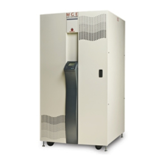
Page 20: Major Components
208 VAC output. An output voltage of 208 VAC is standard with the Galaxy 3000 and does not require any additional cabinetry. If output voltages of 240 VAC, 408 VAC or 600 VAC are required, an auxiliary cabinet is required for the output transformer. -
Page 21: Cabinet Descriptions And Placement
1.1.5.1 Air Flow / Heat Rejection The Galaxy 3000 UPS cabinets generate heat and exhaust air through the top portion of its enclosures. Air intake is through the bottom of the cabinet. All other cabinets are convection cooled. To assist you in planning for your HVAC needs, heat rejection data is provided in Table 1.1, (i.e., 480 VAC input / 480 VAC output). -
Page 22: Ups Cabinet Showing The Airflow And Recommended Clearance
Galaxy 3000 10-30kVA Figure 1-2: UPS Cabinet Showing the Airflow and Recommended Clearance. GRAPHICAL USER INTERFACE AIR EXHAUST ALLOW 36" TOP CLEARANCE FOR FAN EXHAUST DOOR LATCHES LEVELING CASTERS JACKS 2nd AUXILIARY AUXILIARY UPS MODULE EXTERNAL CABINET CABINET BATTERY BANK... -
Page 23: Cabinet Footprints And Electrical Entries
Conduit Plate Locations for top entry The Standard cabinet for the Galaxy 3000 is capable of accepting power input and output cables through a top entry. The conduit plate on the top of the cabinet provides six (6) knockouts for conduit and is secured to the cabinet with four (4) machine screws. -
Page 24: Single Line Diagram
Additional (extended life) batteries, external maintenance bypass switches, and/or output distribution panel boards may be contained in auxiliary cabinets similar in design to the Galaxy 3000 cabinet, or may be contained in third party cabinets or wall mounted units. -
Page 25: Scope
Guides the user through tools and equipment required for unpacking and performing connections required for initial installation. Included are the electrical specifications, environmental recommendations and connection details. The following describes installation procedures and recommendations for the Galaxy 3000 10-30 kVA UPS including receiving, handling, and storage procedures. Prerequisites prior to installation; installation procedures and start-up procedures are also included. -
Page 26: Electrical Connections
Galaxy 3000 unit is opened. However, access to the main, bypass and load connections is made through the removal of the safety panel located in the lower left of the Galaxy 3000 (with the door open). This safety panel is removed by first removing the four (4) screws securing the panel. -
Page 27: Main Ac Input Connections
Installation and User Manual 2.2.1.1 Main AC Input Connections The connections to be made are the three phases, and ground cables from the utility AC power source to the UPS. The main AC input cables are terminated at the Main Input Terminal Blocks (TB1). Complete wiring instructions for your installation are provided on the installation drawings supplied with the equipment. -
Page 28: Connecting Remote Emergency Power Off Cables
Connection of Relay Communication Card The relay communications card contains six programmable dry contact outputs and two programmable dry inputs and is standard on the Galaxy 3000. The inputs and outputs are factory programmed according to functions listed in Table 2-2. -
Page 29: Removing The Cover
Installation and User Manual CAUTION Isolate and lock-out all power sources for this card before making connections. Never connect ELSV (extra low safety voltage) and non-ELSV circuits to the different outputs of the same card. Removing the Cover 1. Remove the cover “3” secured by the screws “1”. 2. -
Page 30: Characteristics Of The Output Contacts
Before starting the Galaxy 3000, be certain that you fully understand the operation of the indicators, controls, and operational sequences. MGE UPS SYSTEMS offers professional start up services in most countries. It is suggested that before applying power to your Galaxy 3000, your contract with MGE for a professional start up with an MGE Field Engineer. -
Page 31: Operation
The following check lists are provided to aid in the successful pre and post start-up of the Galaxy 3000. They include items to verify prior to applying power, and then tests that should be performed (when appropriate) after startup to verify the health and function- ality of all critical modules within the system. -
Page 32: Normal Start Up Procedure
Normal Start Up Procedure With all of the initial safety check lists verified, the Galaxy 3000 UPS system can now be powered. The following procedure should be used after the Galaxy 3000 UPS system has been commissioned (typically by an MGE Field Service Engineer). -
Page 33: Post Start Up Safety Check List
◗ Maintenance bypass procedure. CAUTION As soon as AC input power is supplied to the Galaxy 3000 (customer supplied upstream circuit breaker is in the "ON" position), the load is initially supplied via the "Static Switch." Verify that no error indications are present on the operator interface panel. -
Page 34: Operator Interface Screens
Galaxy 3000 10-30kVA Operator Interface Screens The operator interface screens contained on the Galaxy 3000 Operator Interface provide an easy to use method to access and control the Galaxy features. The Soft Keys are now programmed to allow you to scroll up and down through the list of alarms. Although slightly different in operation, the detail key (soft key #4) must be held down to examine the message details. -
Page 35: Screen Saver Display
When the Galaxy 3000 system has been in continuous operation, the operator interface will present a screen saver display. See Figure 3-2. The product name, "Galaxy 3000", will be moving around the display screen to provide an indication that the unit is functional. See Figure 3-3. -
Page 36: Main Menu Display
From Main Menu display the operator can access hundreds of different displays which will allow the ability to monitor the operating performance of Galaxy 3000, obtain alarm information, change operational settings as well as issue software based commands to various features in the unit. -
Page 37: Power Measurements Display
Installation and User Manual 3.2.5 Power Measurements Display From the Power Measurements display, we can see the power being required by the load on each phase displayed in kVA and in kW. Additionally, the source AC "normal" (AC N) is shown with the current kVA. Pressing the key associated with the multiple documents icon, results in the Current Measurements display. -
Page 38: Voltage Measurements Display
Galaxy 3000 10-30kVA 3.2.7 Voltage Measurements Display From the Voltage Measurements display we can see the voltage currently on any one of the input phases (AC N and AC BP) and each phase of the load, as well as the differential voltage as measured between any two phases of the inputs and the load. -
Page 39: Ratios Display
The top half of the display contains a single line representation of the current operating condition of the Galaxy 3000 unit. Through the use of color changes in the display, it will indicate whether the unit is operating normally, is on bypass, or is currently running on batteries. -
Page 40: 3.2.11 Status Displays Menu
Galaxy 3000 10-30kVA 3.2.11 Status Displays Menu Selecting the Status option from the Main Menu results in another list of available displays. These displays include: Status and Alarms, Event Log, Statistics, History. See Figure 3-13. The Soft Keys have been programmed to allow you to highlight one of these available displays and then to select it (by pressing soft key #4). -
Page 41: Settings Menu
Installation and User Manual 3.2.13 Settings Menu From the Settings menu, we can select a variety of options for the operation of the Galaxy 3000 system. See Figure 3-15. Four (4) options are: Language With an opportunity for the Galaxy 3000 unit to be located in any country, it is possible to select the language of preference from several options. - Page 42 Galaxy 3000 10-30kVA (This page left blank intentionally) 3 —12 86-172010-00 C05...
- Page 43 Maintenance Scope Describes maintenance and safety information on servicing batteries for the Galaxy 3000. Servicing Batteries IMPORTANT SAFETY INSTRUCTIONS FOR SERVICING BATTERIES Servicing of batteries should be performed or supervised by personnel knowledgeable of batteries and the required precautions. Keep unauthorized personnel away from batteries.
- Page 44 Product Name (This page left blank intentionally) 4 —2 86-172010-00 C05...
- Page 45 INC.’s factory or on the job site at MGE UPS SYSTEMS, INC.’s option, any part or parts which are defective, including labor, for a period of 12 months from the date of purchase. The MGE UPS SYSTEMS, INC. shall have the sole right to determine if the parts are to be repaired at the job site or whether they are to be returned to the factory for repair or replacement.
- Page 46 Warranty and Product Registration Thank you for choosing MGE UPS SYSTEMS, INC. for your power protection, distribution, and quality requirements. We are pleased to have you join our increasing family of users. In order to maximize the value you receive from this product, and to ensure that you are kept informed of product or software updates, we recommend that you take a few minutes to register your new purchase.
- Page 47 Customer FAQ or International calls: 1-714-557-1636 Commitment: MGE UPS SYSTEMS, INC. is committed to providing easy to access factory trained experts that will provide responses to any questions that you might have. Scheduling Field Service Engineer Support Scheduling of the MGE Field Service Engineers typically should be done 7 to 10 days before they are required on-site.
- Page 48 Product Name (This page left blank intentionally) W—4 86-172010-00 C05...
- Page 49 Glossary Term used Definition / Meaning And/or. Plus or Minus. ≤ Equal to or less than. Number. °C Degree Celsius. °F Degree Fahrenheit. Ø Phase angle. Ω Ohm; unit of resistance. ® Trade Mark. Second. Normal sequence of phases in three phase power. AC or ac Alternating current, also implies root-mean-square (rms).
- Page 50 Galaxy 3000 10-30kVA DC or dc Direct current, or voltage. Digital Meter The LCD display on the front panel of inverter system. Earth ground A ground circuit that has contact with the earth. ECO Mode Operating mode by which the load is supplied directly by the AC source if it is within the tolerances defined by the user.
- Page 51 Refers to an electronic technician qualified to maintain and repair electronic equipment. Not necessarily qualified to install electrical wiring. Test connector DB-9 type connector on the LCD panel allowing MGE UPS SYSTEMS Customer Support Service technician to access programmable and diagnostic features of the system.
- Page 52 Galaxy 3000 10-30kVA (This page left blank intentionally) G — 4 86-172010-00 C05...
- Page 53 Battery System 1 — 2 Buzzer 3 —11 General Description 1 — 1 Bypass AC Input Connections (optional) 2 — 3 Getting Started with Galaxy 3000 QS—1 BYPASS position QS—6 Bypass Switch 3 —2 Heat Rejection 1 — 3 Humidity 2 — 1 Cabinet Footprints and Electrical Entries 1 —...
- Page 54 Galaxy 3000 10-30kVA Remote Emergency Power Off 2 — 4 Remote Emergency Power Off (REPO) 2 — 4 Nonlinear computer-type loads 1 — 1 Removing the Cover 2 — 5 Normal Shutdown Procedure 3 —3 Replacing the Cover 2 — 5 Normal Start Up Procedure 3 —2...
- Page 55 A free copy of this document may be downloaded from the proprietary MGE Rep Web site. Please contact your MGE UPS SYSTEMS, INC. Representative for assistance. NAME...
- Page 58 . m g e u p s . c o m Contact MGE United States MGE UPS SYSTEMS 1660 Scenic Ave. Costa Mesa, CA 92626 Tel: (714) 557-1636 (800) 523-0142 Fax: (714) 557-9788 email: info@mgeups.com www: mgeups.com...
Need help?
Do you have a question about the Galaxy 3000 and is the answer not in the manual?
Questions and answers