Trane GEH 006 Manual
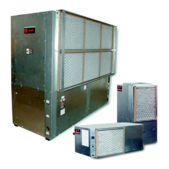
High efficiency
horizontal and vertical
water-source comfort system, 1/2 - 5 tons - 60 hz, 12 1/2 - 25 tons - 60 hz
Hide thumbs
Also See for GEH 006:
- Installation and maintenance manual (119 pages) ,
- Installation, operation and maintenance manual (104 pages)

Related Manuals for Trane GEH 006


Summary of Contents for Trane GEH 006
- Page 1 High Efficiency Horizontal and Vertical Water-Source Comfort System Axiom 1/2 - 5 Tons — 60 HZ 12 1/2 - 25 Tons — 60 HZ WSHP-PRC001-EN...
-
Page 2: Introduction
Introduction Imagine a full range of comfort utiliz- Trane’s new design incorporates Quiet unit design ing efficiency, sound attenuation, in- system advantages such as: tegrated controls, and superior Integrated controls Maximum return-air and maintenance accessibility... Trane supply-air flexibility imagined it, then brought it to life. -
Page 3: Table Of Contents
Table of Contents Introduction Features and Benefits Options Controls Application Considerations Selection Procedures How to Select by Computer Manual Selection Procedure Model Number Description General Data Performance Data Cool and Heat Performance Correction Factors Electrical Performance Fan Performance Waterside Economizer Performance Sound Performance Anti-Freeze Correction Factors Controls... -
Page 4: Features And Benefits
Features and Benefits Design Advantages The horizontal configuration model GEH product offers a range of capacities from 1/2 to 5 ton. This innovative design offers superior field flexibility at the jobsite along with service accessibility. Cabinet The cabinet design includes a modular platform that utilizes similar parts and assemblies throughout the product line. - Page 5 Like it’s horizontal (GEH) counterpart, the GEV offers a range of capacities from 1/2- to 5-ton, and 12 1/2 through 25-ton. Only, with the vertical design, Trane includes a 3 1/3-ton configuration physically sized for condominium installations. The GEV configuration incorporates...
- Page 6 Features and Benefits Field Convertible The bullet listing below shows the available return-air/supply-air combi- nations on the GEH model whether specified by order or modified on-site to meet your unique installation re- quirement. The six combinations in- clude: Left return-air with left supply-air combination UNIT UNIT...
- Page 7 Features and Benefits Vertical Advantages The vertical (model GEV) configuration offers a range of capacities from 12 1/2-ton through 25-ton. The sleek, narrow cabinet is designed to fit through a standard doorway for installation during new construc- tion, or retrofit purposes. The units sturdy cabinet is de- signed for durability, and corrosive resistance.
- Page 8 5 ton unit contains a Figure 8: Plastic drain pan scroll compressor. These different de- Drain Pan signs allow Trane to provide the volt- The unit drain pan is composed of age variations along with noise plastic, corrosive resistive material.
- Page 9 Expansion Valve pressor and single isolation to the co-axial water coil. The combination in All Trane water-source systems in- the double isolation provide additional clude an expansion valve flow meter- attenuation during compressor start ing device.
- Page 10 Features and Benefits Reversing Valve extensive ductwork design. This is a low cost alternative to purchasing, in- A system reversing valve (4-way stalling, and maintaining multiple valve) is included with all heating/ smaller tonnage units to meet the re- cooling units. This valve is piped to be quired air flow demand for the space.
- Page 11 16-gauge compressor enclosure space. 18-gauge single wall front panel 16-gauge single wall front panel This sound reduction package reduces radiated noise from the cabinet. Trane lined compressor enclosure with lined compressor enclosure with double-isolates the compressor and 1/2-inch cabinet insulation...
- Page 12 Features and Benefits Boilerless Control/Electric Heat (option) In cooling dominant regions where heat may be used 15 to 30 days out of the winter season, eliminating the boiler may be an economical advan- tage to the building owner. Eliminat- ing a boiler from the system reduces costs associated with the mechanical system installation, as well as the maintenance and service of the boiler.
- Page 13 Features and Benefits Boilerless Control/Electric Heat Heating/Cooling Mode In heating mode, when the water tem- perature falls below 55 F (factory set- ting), the electric heater is energized, locking out the compressor. The systems electric heat source will continue to be utilized for primary heating until the loop...
- Page 14 Features and Benefits Waterside Economizer (option) The beauty of the waterside economiz- er is it’s ability to take advantage of any loop condition that results in cool water temperatures. A prime example would be during fall, winter and spring when cooling towers have more ca- pacity than required and could be con- trolled to lower temperatures for economizer support.
- Page 15 Water regulating valves should not be Note: Trane places an air separation space. The moisture removal capabili- used with the hot gas reheat option. space between the air-to-refrigerant...
-
Page 16: Controls
Controls by Trane Whether involved in a retrofit or new construction application, Trane has the control design to fit your system requirement. Our control options provide a broad range of packages from the most cost efficient 24 volt standalone to a complete build- ing automation solution, Trane is the right choice in comfort gratification. - Page 17 Features and Benefits Basic Controls Basic 24 Volt Controls The basic 24 V electro-mechanical unit control provides component protec- tion devices for maximum system reli- ability. Each device is factory mounted, wired and tested. Figure 25: Basic 24 volt control box The Basic 24 volt control package is only available for the 1/2 through 5-ton unit sizes.
- Page 18 Features and Benefits Basic Controls Stand-alone System The 24 volt electro-mechanical design may be applied as a stand-alone control system. The stand-alone design provides accurate temperature control directly through a wall-mounted mercury bulb or electronic thermostat. This system set-up may be utilized in a replacement design where a single unit retrofit is needed.
- Page 19 Features and Benefits Deluxe Controls Deluxe 24V Electronic Controls The deluxe 24V electronic unit control provides component protection devices similar to the basic design, but contains upgraded features to maximize system performance to extend the system life. Each device, is factory mounted, wired, and tested in the unit.
- Page 20 The board is unique to Trane start-up time delays have expired, and open after the compressor starts. If the water-source products and is all safeties have been satisfied.
- Page 21 With a multiple unit installation, the units may be daisy-chained directly to the Trane Tracer loop controller (TLC), pump(s), boiler, and tower for a complete networked water-source system. The TLC provides a night setback output, and a pump request input for system optimization.See...
- Page 22 Features and Benefits ZN510 & ZN524 Controls Tracer ZN510 & ZN524 Controls The Tracer ZN510 and ZN524 are direct digital control (DDC) systems specifically designed for single and dual circuited water-source equipment to provide control of the entire unit, as well as outputs for unit status and fault detection. Each de- vice is factory installed, commissioned, and tested to ensure the highest level of quality in unit design.
- Page 23 Features and Benefits ZN510 & ZN524 Controls Direct Digital Controls will default to the heating In an unoccupied situation, the When the ZN510 or ZN524 controller is (de-energized) state. controller assumes the building is va- linked directly to the Tracer Summit, cant, which normally falls in evening Fan Operation each Tracer Summit building...
- Page 24 When the building owners choice is livering air that is cold enough to an isolation valve has been opened, it Trane Tracer controls, the ZN524 con- sweat discharge air grilles. Coil icing will remain open for a 10 minute mini- troller is required when any of the fol- protection will also be provided.
- Page 25 This sharing of information is made possibe via a twisted pair of wire and a building automation system or through Trane’s Rover service tool . An advantage of installing a ZN510/ZN524 is its capability to work with other LonTalk certified controllers.
-
Page 26: Application Considerations
Application Considerations How it Works? Cooling Mode (Figure 34) If cooling is called for, the thermostat activates the centrifugal blower and sets the reversing valve into the cooling position. If all safeties are met, high temperature refrigerant vapor is pumped from the compressor throught the reversing valve to the refrigerant-to-water heat exchanger. - Page 27 Application Considerations Flexibility A ground source (geothermal) A geothermal loop can be installed ei- The high efficiency vertical and hori- system consist of a: ther horizontally or vertically. Vertical zontal water-source heat pump sys- loops require less overall land area to tem is versatile for installation in •...
- Page 28 Application Considerations Boiler/Cooling Tower Application In a boiler/cooling tower application (Figure 37), the closed water-loop, along with multiple water-source heat pumps are utilized in a more conventional manner. Typically, a boiler is used to maintain closed-loop temperatures above 60 F, and a cooling tower is used to maintain closed-loop temperature below 90 F.
- Page 29 Application Considerations Open-Loop Design Ground water from a well can be used to exchange heat in an open-loop system Figure 39. The ground water is pumped from the well into the geothermal heat pump, where heat is extracted or rejected and then returned to an aquifer.
- Page 30 Many are provided by the contractor. Hose kits are used to connect the water supply and return line to the water inlets and outlets. Trane of- fers various hose kit combina- tions to better facilitate system flow balancing.
- Page 31 60 F. Hose kits are used to connect the water supply and return line to the water inlets and outlets. Trane of- fers various hose kit combinations to better facilitate system flow bal- ancing. These flexible hoses also...
- Page 32 5-ton GEV to a central pumping sys- below the vertical unit. This field Trane includes various hose kit tem, or a distributed pumping system, provided piece should be equal to combinations to better facilitate...
- Page 33 Application Considerations Hanging the Horizontal The horizontal unit GEH is a ceiling hung unit. It is usually applied as a totally concealed unit above an acoustical ceiling grid. Because the GEH is equipped with several inlet and discharge arrangements, it allows for numerous application needs, and is field convertible at the jobsite.
- Page 34 Application Considerations Condensate Traps When designing a condensate trap for the water-source system, it’s important to consider the unit’s draw through design. Under normal conditions, condensate runs down the coil fins and drips into a condensate pan. In situations where no trap is installed, the water level that would be maintained in the trap to create a seal, backflows through the drainline into the unit.
- Page 35 Considerations Installation Made Easy Installing a horizontal unit inside a corridor to enhance sound attenuation provides value to duct design. Trane takes this fact one step further. The new GEH design offers same side return-air/supply-air access to the unit. This access is contained within the overall dimension of the units length as shown in Figure 44.
- Page 36 Application Considerations Duct Design for Noise Control Proper acoustics are often a design requirement. Most of the problems that are associated with HVAC generated sound can be avoided by properly selecting and locating the components of the system. Acoustical modeling should be used to find the lowest cost design to meet a specific sound...
- Page 37 Application Considerations Sound control applies to the return side of the duct design as well as the supply side. Figure 48, demonstrates a poor installation. Note that the return air opening is close to the cabinet of the unit. Figure 49 graphic represents proper installation of return-air duct.
- Page 38 In the heating mode, the valve con- device. Trane places a thermal expan- trolling the water flow is referred to a a sion valve on all water-source and reverse acting valve. As the spring ten-...
- Page 39 Application Considerations Types of Applications gasket-plate heat exchanger to close In systems that use a boiler/cooling the loop, or a closed-circuit fluid tower design, water pumps are placed cooler design. between the auxiliary equipment Hybrid Systems (boiler, cooling tower, etc.) and the Some systems have evolved into a hy- WSHPs to ensure positive water brid (combination) system due to...
-
Page 40: Selection Procedures
If this program has not been made (27-degree C) dry bulb and 66.2-de- cations is based upon humidity levels available, ask a local Trane sales engi- gree F (19-degree C) wet bulb entering for the climate, and goals for operating... -
Page 41: Manual Selection Procedure
Selection Procedure New Performance Ratings All performance data in this catalog is rated to the new ARI-ISO 13256-1 standard . The following information should be used in gaining a clearer understanding of the differences on the new ARI-ISO standard versus the ARI 320/330 standards of today. - Page 42 Selection Procedure ISO Cooling Data Calculations Examples for cooling calculations in reference to ARI-ISO 13256-1 is listed below. This step-by-step example, utilizes the unit information as shown in SP-3, to verify the ISO calculations found in SP-4. SP-3: Unit information SP-4: ISO calculations Unit Information ISO Calculations...
- Page 43 Selection Procedure ISO Heating Data Calculations Examples for heating calculations in reference to ARI-ISO 13256-1 is listed below. This step-by-step example, utilizes the unit information as shown in SP-5, to verify the ISO calculations found in SP-6. SP-5: Unit information SP-6: ISO calculations Unit Information ISO Calculations...
-
Page 44: Model Number Description
1 = 208/60/1 6 = 220-240/50/1 DIGIT 13: CUSTOMER CHANNEL J = Fan Status, Filter Maintenance 2 = 230/60/1 7 = 265/60/1 1 = Boiler/Tower Design for Trane Timer and Condensate Overflow 3 = 208/60/3 8 = 230/60/3 Commercial Group Sensor... - Page 45 Model Number DIGITS 23: UNIT MOUNTED DIGITS 27: PAINT COLOR DISCONNECT 0 = No Paint Selection Available 0 = No Unit Mounted Disconnect DIGITS 28: OUTSIDE AIR DIGITS 24: FILTER TYPE 0 = No Outside Air Option Available 0 = 1" Filter; No Duct Flange 1 = 1"...
-
Page 46: General Data
General Data Table G1: General data about the units Model GEH Unit Size Length (in) Height (in) Width (in) Compressor Type Rotary Rotary Rotary Rotary Approximate Weight with Pallet (lb) Approximate Weight without Pallet (lb) Filter Size Actual (in) 14 5/8 x 20 1/4 14 5/8 x 20 1/4 14 5/8 x 20 1/4 14 5/8 x 20 1/4... - Page 47 General Data Table G4: General data about the units Model GEV Unit Size Length (in) 21 1/2 21 1/2 21 1/2 21 1/2 21 1/2 Height (in) 31 1/4 31 1/4 31 1/4 31 1/4 39 1/4 Width (in) 19 1/2 19 1/2 19 1/2 19 1/2...
- Page 48 General Data Air-to-Refrigerant Coils Table G16: GEV 150 (dual compr. circuit) Table G8: GEH/GEV 006, 009 Table G12: GEV 018, 024, 030, 040 Working Pressure Working Pressure Working Pressure Tubes High Tubes High Tubes High Tubes Deep Tubes Deep Tubes Deep No.
-
Page 49: Performance Data
Performance Data ARI-ISO (WLHP/GLHP) Table P1: ARI-ISO Performance Performance data is tabulated for cooling at 80.6 F DB/66.2 F WB entering air, and for heating at 68 F DB entering air at ARI/ISO 13256-1 rated CFM. For conditions other than what is tabulated, multipliers must be used to correct performance. See the Fan Correction Factor Tables for CFM other than rated, and the Cooling or Heating correction factors for variations in entering air temperature. - Page 50 Performance Data 006-Cooling Table P2: GEH/GEV 006 Cooling Performance Performance data is tabulated for cooling at 80.6 F DB/66.2 F WB entering air at ARI/ISO 13256-1 rated CFM. For conditions other than what is tabulated, multipliers must be used to correct performance. See the fan correction factors Table for CFM other than rated and the cooling correction factors for variations in entering air temperature.
- Page 51 Performance Data 006-Heating Table P3: GEH/GEV 006 Heating Performance Performance data is tabulated for heating at 68 F DB entering air at ARI/ISO 13256-1 rated CFM. For conditions other than what is tabulated, multipliers must be used to correct performance. See the fan correction factors Table for CFM other than rated and the heating correction factors for variations in entering air temperature.
- Page 52 Performance Data 009-Cooling Table P5: GEH/GEV 009 Cooling Performance Performance data is tabulated for cooling at 80.6 F DB/66.2 F WB entering air at ARI/ISO 13256-1 rated CFM. For conditions other than what is tabulated, multipliers must be used to correct performance. See the fan correction factors Table for CFM other than rated and the cooling correction factors for variations in entering air temperature.
- Page 53 Performance Data 009-Heating Table P6: GEH/GEV 009 Heating Performance Performance data is tabulated for heating at 68 F DB entering air at ARI/ISO 13256-1 rated CFM. For conditions other than what is tabulated, multipliers must be used to correct performance. See the fan correction factors Table for CFM other than rated and the heating correction factors for variations in entering air temperature.
- Page 54 Performance Data 012-Cooling Table P8: GEH/GEV 012 Cooling Performance Performance data is tabulated for cooling at 80.6 F DB/66.2 F WB entering air at ARI/ISO 13256-1 rated CFM. For conditions other than what is tabulated, multipliers must be used to correct performance. See the fan correction factors Table for CFM other than rated and the cooling correction factors for variations in entering air temperature.
- Page 55 Performance Data 012-Heating Table P9: GEH/GEV 012 Heating Performance Performance data is tabulated for heating at 68 F DB entering air at ARI/ISO 13256-1 rated CFM. For conditions other than what is tabulated, multipliers must be used to correct performance. See the fan correction factors Table for CFM other than rated and the heating correction factors for variations in entering air temperature.
- Page 56 Performance Data 015-Cooling Table P11: GEH/GEV 015 Cooling Performance Performance data is tabulated for cooling at 80.6 F DB/66.2 F WB entering air at ARI/ISO 13256-1 rated CFM. For conditions other than what is tabulated, multipliers must be used to correct performance. See the fan correction factors Table for CFM other than rated and the cooling correction factors for variations in entering air temperature.
- Page 57 Performance Data 015-Heating Table P12: GEH/GEV 015 Heating Performance Performance data is tabulated for heating at 68 F DB entering air at ARI/ISO 13256-1 rated CFM. For conditions other than what is tabulated, multipliers must be used to correct performance. See the fan correction factors Table for CFM other than rated and the heating correction factors for variations in entering air temperature.
- Page 58 Performance Data 018-Cooling Table P14: GEH/GEV 018 Cooling Performance Performance data is tabulated for cooling at 80.6 F DB/66.2 F WB entering air at ARI/ISO 13256-1 rated CFM. For conditions other than what is tabulated, multipliers must be used to correct performance. See the fan correction factors Table for CFM other than rated and the cooling correction factors for variations in entering air temperature.
- Page 59 Performance Data 018-Heating Table P15: GEH/GEV 018 Heating Performance Performance data is tabulated for heating at 68 F DB entering air at ARI/ISO 13256-1 rated CFM. For conditions other than what is tabulated, multipliers must be used to correct performance. See the fan correction factors Table for CFM other than rated and the heating correction factors for variations in entering air temperature.
- Page 60 Performance Data 024-Cooling Table P17: GEH/GEV 024 Cooling Performance Performance data is tabulated for cooling at 80.6 F DB/66.2 F WB entering air at ARI/ISO 13256-1 rated CFM. For conditions other than what is tabulated, multipliers must be used to correct performance. See the fan correction factors Table for CFM other than rated and the cooling correction factors for variations in entering air temperature.
- Page 61 Performance Data 024-Heating Table P18: GEH/GEV 024 Heating Performance Performance data is tabulated for heating at 68 F DB entering air at ARI/ISO 13256-1 rated CFM. For conditions other than what is tabulated, multipliers must be used to correct performance. See the fan correction factors Table for CFM other than rated and the heating correction factors for variations in entering air temperature.
- Page 62 Performance Data 030-Cooling Table P20: GEH/GEV 030 Cooling Performance Performance data is tabulated for cooling at 80.6 F DB/66.2 F WB entering air at ARI/ISO 13256-1 rated CFM. For conditions other than what is tabulated, multipliers must be used to correct performance. See the fan correction factors Table for CFM other than rated and the cooling correction factors for variations in entering air temperature.
- Page 63 Performance Data 030-Heating Table P21: GEH/GEV 030 Heating Performance Performance data is tabulated for heating at 68 F DB entering air at ARI/ISO 13256-1 rated CFM. For conditions other than what is tabulated, multipliers must be used to correct performance. See the fan correction factors Table for CFM other than rated and the heating correction factors for variations in entering air temperature.
- Page 64 Performance Data 036-Cooling Table P23: GEH/GEV 036 Cooling Performance Performance data is tabulated for cooling at 80.6 F DB/66.2 F WB entering air at ARI/ISO 13256-1 rated CFM. For conditions other than what is tabulated, multipliers must be used to correct performance. See the fan correction factors Table for CFM other than rated and the cooling correction factors for variations in entering air temperature.
- Page 65 Performance Data 036-Heating Table P24: GEH/GEV 036 Heating Performance Performance data is tabulated for heating at 68 F DB entering air at ARI/ISO 13256-1 rated CFM. For conditions other than what is tabulated, multipliers must be used to correct performance. See the fan correction factors Table for CFM other than rated and the heating correction factors for variations in entering air temperature.
- Page 66 Performance Data 040-Cooling Table P26: GEV 040 Cooling Performance Performance data is tabulated for cooling at 80.6 F DB/66.2 F WB entering air at ARI/ISO 13256-1 rated CFM. For conditions other than what is tabulated, multipliers must be used to correct performance. See the fan correction factors Table for CFM other than rated and the cooling correction factors for variations in entering air temperature.
- Page 67 Performance Data 040-Heating Table P27: GEV 040 Heating Performance Performance data is tabulated for heating at 68 F DB entering air at ARI/ISO 13256-1 rated CFM. For conditions other than what is tabulated, multipliers must be used to correct performance. See the fan correction factors Table for CFM other than rated and the heating correction factors for variations in entering air temperature.
- Page 68 Performance Data 042-Cooling Table P29: GEH/GEV 042 Cooling Performance Performance data is tabulated for cooling at 80.6 F DB/66.2 F WB entering air at ARI/ISO 13256-1 rated CFM. For conditions other than what is tabulated, multipliers must be used to correct performance. See the fan correction factors Table for CFM other than rated and the cooling correction factors for variations in entering air temperature.
- Page 69 Performance Data 042-Heating Table P30: GEH/GEV 042 Heating Performance Performance data is tabulated for heating at 68 F DB entering air at ARI/ISO 13256-1 rated CFM. For conditions other than what is tabulated, multipliers must be used to correct performance. See the fan correction factors Table for CFM other than rated and the heating correction factors for variations in entering air temperature.
- Page 70 Performance Data 048-Cooling Table P32: GEH/GEV 048 Cooling Performance Performance data is tabulated for cooling at 80.6 F DB/66.2 F WB entering air at ARI/ISO 13256-1 rated CFM. For conditions other than what is tabulated, multipliers must be used to correct performance. See the fan correction factors Table for CFM other than rated and the cooling correction factors for variations in entering air temperature.
- Page 71 Performance Data 048-Heating Table P33: GEH/GEV 048 Heating Performance Performance data is tabulated for heating at 68 F DB entering air at ARI/ISO 13256-1 rated CFM. For conditions other than what is tabulated, multipliers must be used to correct performance. See the fan correction factors Table for CFM other than rated and the heating correction factors for variations in entering air temperature.
- Page 72 Performance Data 060-Cooling Table P35: GEH/GEV 060 Cooling Performance Performance data is tabulated for cooling at 80.6 F DB/66.2 F WB entering air at ARI/ISO 13256-1 rated CFM. For conditions other than what is tabulated, multipliers must be used to correct performance. See the fan correction factors Table for CFM other than rated and the cooling correction factors for variations in entering air temperature.
- Page 73 Performance Data 060-Heating Table P36: GEH/GEV 060 Heating Performance Performance data is tabulated for heating at 68 F DB entering air at ARI/ISO 13256-1 rated CFM. For conditions other than what is tabulated, multipliers must be used to correct performance. See the fan correction factors Table for CFM other than rated and the heating correction factors for variations in entering air temperature.
- Page 74 Performance Data 150-Cooling Table P-38: GEV 150 Cooling Performance Performance data is tabulated for cooling at 80.6 F DB/66.2 F WB entering air at ARI/ISO 13256-1 rated CFM. For conditions other than what is tabulated, multipliers must be used to correct performance. See the fan correction factors Table for CFM other than rated and the cooling correction factors for variations in entering air temperature.
- Page 75 Performance Data 150 Heating Table P-39: GEV 150 Heating Performance Performance data is tabulated for heating at 68 F DB entering air at ARI/ISO 13256-1 rated CFM. For conditions other than what is tabulated, multipliers must be used to correct performance. See the fan correction factors Table for CFM other than rated and the heating correction factors for variations in entering air temperature.
- Page 76 Performance Data 180-Cooling Table P-42: GEV 180 Cooling Performance Performance data is tabulated for cooling at 80.6 F DB/66.2 F WB entering air at ARI/ISO 13256-1 rated CFM. For conditions other than what is tabulated, multipliers must be used to correct performance. See the fan correction factors Table for CFM other than rated and the cooling correction factors for variations in entering air temperature.
- Page 77 Performance Data 180-Heating Table P-43: GEV 180 Heating Performance Performance data is tabulated for heating at 68 F DB entering air at ARI/ISO 13256-1 rated CFM. For conditions other than what is tabulated, multipliers must be used to correct performance. See the fan correction factors Table for CFM other than rated and the heating correction factors for variations in entering air temperature.
- Page 78 Performance Data 240-Cooling Table P-46: GEV 240 Cooling Performance Performance data is tabulated for cooling at 80.6 F DB/66.2 F WB entering air at ARI/ISO 13256-1 rated CFM. For conditions other than what is tabulated, multipliers must be used to correct performance. See the fan correction factors Table for CFM other than rated and the cooling correction factors for variations in entering air temperature.
- Page 79 Performance Data 240-Heating Table P-47: GEV 240 Heating Performance Performance data is tabulated for heating at 68 F DB entering air at ARI/ISO 13256-1 rated CFM. For conditions other than what is tabulated, multipliers must be used to correct performance. See the fan correction factors Table for CFM other than rated and the heating correction factors for variations in entering air temperature.
- Page 80 Performance Data 300-Cooling (0.45 ESP) Table P-50: GEV 300 Cooling Performance Performance data is tabulated for cooling at 80.6 F DB/66.2 F WB entering air at ARI/ISO 13256-1 rated CFM. For conditions other than what is tabulated, multipliers must be used to correct performance. See the fan correction factors Table for CFM other than rated and the cooling correction factors for variations in entering air temperature.
- Page 81 Performance Data 300-Heating (0.45 ESP) Table P-51: GEV 300 Heating Performance Performance data is tabulated for heating at 68 F DB entering air at ARI/ISO 13256-1 rated CFM. For conditions other than what is tabulated, multipliers must be used to correct performance. See the fan correction factors Table for CFM other than rated and the heating correction factors for variations in entering air temperature.
- Page 82 Performance Data 300-Cooling (0.65 ESP) Table P-54: GEV 300 Cooling Performance Performance data is tabulated for cooling at 80.6 F DB/66.2 F WB entering air at ARI/ISO 13256-1 rated CFM. For conditions other than what is tabulated, multipliers must be used to correct performance. See the fan correction factors Table for CFM other than rated and the cooling correction factors for variations in entering air temperature.
- Page 83 Performance Data 300-Heating (0.65 ESP) Table P-55: GEV 300 Heating Performance Performance data is tabulated for heating at 68 F DB entering air at ARI/ISO 13256-1 rated CFM. For conditions other than what is tabulated, multipliers must be used to correct performance. See the fan correction factors Table for CFM other than rated and the heating correction factors for variations in entering air temperature.
-
Page 84: Correction Factors
Performance Data Correction Factors Table P58: 006-060 Correction Factors for Variation in Entering Air Temperature Cooling Cooling Cooling Sensible vs Entering Dry Bulb Heating Heating Heating Entering Capacity Input Multipliers Entering Capacity Input 65.6 70.6 75.6 80.6 85.6 Air WB F Watts Air DB F Watts... -
Page 85: Electrical Performance
Performance Data Electrical E1-Electrical performance Model Volts Total Comp Comp No. of Blower Blower Minimum Maximum Electric Electric Com- Motor Motor Motor Circuit Overcur- Heat Heat (ea) (ea) pres. Ampacity rent Amps Protective Device 115/60/1 5.70 36.2 1.20 1/12 208/60/1 2.80 17.7 0.60... - Page 86 Performance Data Electrical E2-Electrical performance (continued) Model Volts Total Comp Comp No. of Blower Blower Minimum Maximum Electric Electric Com- Motor Motor Motor Circuit Overcur- Heat Heat (ea) (ea) pres. Ampacity rent Amps Protective Device 208/60/1 14.2 12.40 61.0 17.4 2.10 17.6 208/60/1...
- Page 87 Performance Data Electrical E3-Electrical performance (continued) Model Volts Total Comp Comp No. of Blower Blower Minimum Maximum Electric Electric Com- Motor Motor Motor Circuit Overcur- Heat Heat (ea) (ea) pres. Ampacity rent Amps Protective Device 208/60/1 25.8 20.40 102.0 28.5 5.40 30.9 208/60/1...
- Page 88 Performance Data Electrical E4-Electrical performance (continued) Model Volts Total Comp Comp No. of Blower Blower Minimum Maximum Electric Electric Com- Motor Motor Motor Circuit Overcur- Heat Heat (ea) (ea) pres. Ampacity rent Amps Protective Device 208/60/3 79.4 31.70 232.0 49.5 16.00 87.4 230/60/3...
-
Page 89: Fan Performance
Performance Data Fan Performance Table F1: Fan performance for standard static motor includes wet coil, no filter Model External Static Pressure (in. of wg) 1.05 Number 006 High 342 009 High 342 012 High 456 015 High 550 018 High 684 024 High 912 030 High 1009 1009 988... - Page 90 Performance Data Fan Performance Table F-2: Fan performance (high static option) includes wet coil, no filter Model External Static Pressure (in. of wg) 1.05 Number High High High High High High High 1009 1097 1074 1053 1033 1011 988 1009 988 High 1368 1396 1364 1329 1291 1249 1203 1154 1100 1042 979...
- Page 91 Performance Data Fan Performance - 150 Table F5: GEV 150 - Front/Back Supply (includes wet coil, no filter) GEV 150 - Front/Back Supply (includes wet coil, no filter) Unit External Static Pressure inches W.G. ( Wet Coil, 3% Drive Loss Included & No Return Air Filter) Airfow RPM BHP RPM BHP RPM BHP RPM BHP RPM BHP RPM BHP RPM BHP RPM BHP RPM BHP RPM BHP RPM BHP RPM BHP 4000...
- Page 92 Performance Data Fan Performance - 150 Table F6: GEV 150 - Top Supply (includes wet coil, no filter) GEV 150 - Top Supply (includes wet coil, no filter) Unit External Static Pressure inches W.G. ( Wet Coil, 3% Drive Loss Included & No Return Air Filter) Airfow RPM BHP RPM BHP RPM BHP RPM BHP RPM BHP RPM BHP RPM BHP RPM BHP RPM BHP RPM BHP RPM BHP RPM BHP 4000...
- Page 93 Performance Data Fan Performance - 180 Table F7: GEV 180 - Front/Back Supply (includes wet coil, no filter) GEV 180 - Front/Back Supply (includes wet coil, no filter) Std Airfow Unit External Static Pressure inches W.G. ( Wet Coil, 3% Drive Loss Included & No Return Air Filter) RPM BHP RPM BHP RPM BHP RPM BHP RPM BHP RPM BHP RPM BHP RPM BHP RPM BHP RPM BHP RPM BHP RPM BHP 4800 547 1.21 580 1.31 610 1.41 639 1.50...
- Page 94 Performance Data Fan Performance - 180 Table F8: GEV 180 - Top Supply (includes wet coil, no filter) GEV 180 - Top Supply (includes wet coil, no filter) Unit External Static Pressure inches W.G. ( Wet Coil, 3% Drive Loss Included & No Return Air Filter) Airfow RPM BHP RPM BHP RPM BHP RPM BHP RPM BHP RPM BHP RPM BHP RPM BHP RPM BHP RPM BHP RPM BHP RPM BHP 4800...
- Page 95 Performance Data Fan Performance - 240 Table F9: GEV 240 - Front/Back Supply (includes wet coil, no filter) GEV 240 - Front/Back Supply (includes wet coil, no filter) Unit External Static Pressure inches W.G. (Wet Coil, 3% Drive Loss Included & No Return Air Filter) Airfow RPM BHP RPM BHP RPM BHP RPM BHP RPM BHP RPM BHP RPM BHP RPM BHP RPM BHP RPM BHP RPM BHP RPM BHP 6400...
- Page 96 Performance Data Fan Performance - 240 Table F10: GEV 240 - Top Supply (includes wet coil, no filter) GEV 240 - Top Supply (includes wet coil, no filter) Unit External Static Pressure inches W.G. ( Wet Coil, 3% Drive Loss Included & No Return Air Filter) Airfow RPM BHP RPM BHP RPM BHP RPM BHP RPM BHP RPM BHP RPM BHP RPM BHP RPM BHP RPM BHP RPM BHP RPM BHP 6400...
- Page 97 Performance Data Fan Performance - 300 Table F11: GEV 300 - Front/Back Supply (includes wet coil, no filter) GEV 300 - Front/Back Supply (includes wet coil, no filter) with 11 x 15 blower wheel Unit External Static Pressure inches W.G. ( Wet Coil, 3% Drive Loss Included & No Return Air Filter) Airfow RPM BHP RPM BHP RPM BHP RPM BHP RPM BHP RPM BHP RPM BHP RPM BHP RPM BHP RPM BHP RPM BHP RPM BHP 8000...
- Page 98 Performance Data Fan Performance - 300 Table F12: GEV 300 - Front/Back Supply (includes wet coil, no filter) GEV 300 - Front/Back Supply (includes wet coil, no filter) with 12 x 12 blower wheel Unit External Static Pressure inches W.G. (Wet Coil, 3% Drive Loss Included &...
- Page 99 Performance Data Fan Performance - 300 Table F13: GEV 300 - Top Supply (includes wet coil, no filter) GEV 300 - Top Supply (includes wet coil, no filter) with 11 x 15 blower wheel Unit External Static Pressure inches W.G. ( Wet Coil, 3% Drive Loss Included & No Return Air Filter) Airfow RPM BHP RPM BHP RPM BHP RPM BHP RPM BHP RPM BHP RPM BHP RPM BHP RPM BHP RPM BHP RPM BHP RPM BHP 8000...
- Page 100 Performance Data Fan Performance - 300 Table F14: GEV 300 - Top Supply (includes wet coil, no filter) GEV 300 - Top Supply (includes wet coil, no filter) with 12 x 12 blower wheel Unit External Static Pressure inches W.G. ( Wet Coil, 3% Drive Loss Included & No Return Air Filter) Airfow RPM BHP RPM BHP RPM BHP RPM BHP RPM BHP RPM BHP RPM BHP RPM BHP RPM BHP RPM BHP 8000...
-
Page 101: Waterside Economizer Performance
Performance Data Waterside Economizer Performance data is tabulated for cooling at 80 F DB/67 F WB entering air and 45 F entering fluid at ARI 410 rated SCFM. Table W1: Waterside Economizer Performance Data (1/2 through 5 Tons) Input Data Output Data Tonnage Model... -
Page 102: Sound Performance
Performance Data Sound The Challenge of Low Sound The GEH product line was developed to be the industry leader in noise performance. To achieve that goal, state of the art acoustic design and test technologies were used to identify and treat the dominant noise and vibration trans- mission paths in each unit. - Page 103 Performance Data Sound As an example, of the effect of environment, consider the sound produced by a drum. Clearly, the drum is perceived to be louder in a bathroom with hard tile walls than it is in the middle of a football field. Also, the farther one moves away from the drum, the quieter it sounds.
- Page 104 Performance Data Sound Mock-up Tests of the WSHP Because the transfer function (the difference between sound pressure and sound power) of a water-source comfort system is often a complex function of environment and operating mode, we have found it advantageous to supplement sound power certification tests with sound pressure measurements taken in a mock-up of a typical environment.
- Page 105 Performance Data Sound Table P59: GEH rated summary of NC sound pressure levels (Enhanced Sound Package) Unit Size Sound Pressure - NC High Speed Hi-Med Speed Low-Med Speed Low Speed Compressor Compressor Compressor Compressor Compressor Compressor Compressor Compressor Compressor Compressor Compressor Compressor Compressor...
-
Page 106: Antifreeze Correction Factors
Performance Data Antifreeze Correction Factors Table A1: Correction Factors for AntifreezeSolutions Methanol Concentration by Volume Item Cool .9980 .9965 .9949 .9932 .9915 Capacity Heat .9950 .9898 .9846 .9794 .9742 Capacity Pressure 1.023 1.057 1.091 1.122 1.160 Drop Ethylene Glycol Cool .9955 .9912 .9870... -
Page 107: Controls
Control Wiring Basic 24V - 1 PH 208V-60HZ-1PH WSHP-PRC001-EN... - Page 108 Control Wiring Deluxe 24V - 3 PH 208V-60HZ-3PH WSHP-PRC001-EN...
- Page 109 Control Wiring Tracer ZN510-1PH 208V-60HZ-1PH WSHP-PRC001-EN...
- Page 110 Dimensional Data Tracer ZN524-3PH 460V-60HZ-3PH WSHP-PRC001-EN...
-
Page 111: Dimensional Data
Dimensional Data Weight Distribution Weight Distribution Approximate weight distribution for the GEH model is indicated in Figure 54. Tolerance on the weights deter- mined are ±15 %. Total weights for each unit are list- ed below. Shipping Running GEH Unit Weight Weight (lbs) - Page 112 Dimensional Data Left Return/Left Supply Unit NPTI NPTI 40" 20" 15" 20" 15" 6 7/8" 8" 11 1/2" 4 1/4" 2 1/8" 1/2" 1/2" 38 3/4" 18 3/4" 13 5/8" 18 1/2" 006,009 (1016) (508) (381) (508) (381) (175) (203) (292) (108) (54)
- Page 113 Dimensional Data Left Return/Back Supply Unit NPTI NPTI 40" 20" 15" 20" 15" 6 7/8" 8" 11 1/2" 4 1/4" 2 1/8" 1/2" 1/2" 38 3/4" 18 3/4" 13 5/8" 18 1/2" 006,009 (1016) (508) (381) (508) (381) (175) (203) (292) (108) (54)
- Page 114 Dimensional Data Left Return/Right Supply Unit NPTI NPTI 40" 20" 15" 20" 15" 6 7/8" 8" 11 1/2" 4 1/4" 2 1/8" 1/2" 1/2" 38 3/4" 18 3/4" 13 5/8" 18 1/2" 006,009 (1016) (508) (381) (508) (381) (175) (203) (292) (108) (54)
- Page 115 Dimensional Data Right Return/Left Supply Unit NPTI NPTI 40" 20" 15" 20" 15" 6 7/8" 8" 11 1/2" 4 1/4" 2 1/8" 1/2" 1/2" 38 3/4" 18 3/4" 13 5/8" 18 1/2" 006,009 (1016) (508) (381) (508) (381) (175) (203) (292) (108) (54)
- Page 116 Dimensional Data Right Return/Back Supply Unit NPTI NPTI 40" 20" 15" 20" 15" 6 7/8" 8" 11 1/2" 4 1/4" 2 1/8" 1/2" 1/2" 38 3/4" 18 3/4" 13 5/8" 18 1/2" 006,009 (1016) (508) (381) (508) (381) (175) (203) (292) (108) (54)
- Page 117 Dimensional Data Right Return/Right Supply Unit NPTI NPTI 40" 20" 15" 20" 15" 6 7/8" 8" 11 1/2" 4 1/4" 2 1/8" 1/2" 1/2" 38 3/4" 18 3/4" 13 5/8" 18 1/2" 006,009 (1016) (508) (381) (508) (381) (175) (203) (292) (108) (54)
- Page 118 Dimensional Data Waterside Economizer Filter Size Unit NPTI NPTI (nominal) 1/2" 1/2" 16 1/8" 13 5/8" 1 1/2" 10 3/4" 23" 2 1/4" 7 1/2" 1/2" 1" 4" 18 1/2" 14 3/4" x 23 3/4" 006-015 (12.7) (12.7) (410) (346) (38) (273) (584)
- Page 119 Dimensional Data Left Return/Top Supply Unit W.I. W.O. Drain NPTI NPTI 19 1/2" 31 1/4" 21 1/2" 11 1/2" 4" 3 3/4" 16 1/2" 15" 18" 6 7/8" 8" 3/4" 2" 1/2" 1/2" 3/4" 006-015 (495) (794) (546) (292) (102) (95) (419) (381)
- Page 120 Dimensional Data Right Return/Top Supply Unit W.I. W.O. Drain NPTI NPTI 19 1/2" 31 1/4" 21 1/2" 11 1/2" 4" 3 3/4" 16 1/2" 15" 18" 6 7/8" 8" 3/4" 2" 1/2" 1/2" 3/4" 006-015 (495) (794) (546) (292) (102) (95) (419) (381)
- Page 121 Dimensional Data Left Return/Back Supply Unit W.I. W.O. Drain NPTI NPTI 19 1/2" 31 1/4" 21 1/2" 11 1/2" 4" 3 3/4" 16 1/2" 15" 18" 6 7/8" 8" 3/4" 2" 1/2" 1/2" 3/4" 006-015 (495) (794) (546) (292) (102) (95) (419) (381)
- Page 122 Dimensional Data Right Return/Back Supply Unit W.I. W.O. Drain NPTI NPTI 19 1/2" 31 1/4" 21 1/2" 11 1/2" 4" 3 3/4" 16 1/2" 15" 18" 6 7/8" 8" 3/4" 2" 1/2" 1/2" 3/4" 006-015 (495) (794) (546) (292) (102) (95) (419) (381)
- Page 123 Dimensional Data Front Return/Back Supply 12 1/2 & 15 Ton WSHP-PRC001-EN...
- Page 124 Dimensional Data Back Return/Front Supply 12 1/2 & 15 Ton WSHP-PRC001-EN...
- Page 125 Dimensional Data Front Return/Top Supply 12 1/2 & 15 Ton WSHP-PRC001-EN...
- Page 126 Dimensional Data Back Return/Top Supply 12 1/2 & 15 Ton WSHP-PRC001-EN...
- Page 127 Dimensional Data Front Return/Back Supply 20 & 25 Ton Unit Size 15 5/8" 13 1/2" 12" 51 5/8" 20 7/8" 20 Ton (397) (341) (305) (1310) (530) 25 Ton 14 3/4" 15 7/8" 13 7/8" 49 1/8" 23 1/2" Std Static (375) (403) (352)
- Page 128 Dimensional Data Back Return/Front Supply 20 & 25 Ton Unit Size 15 5/8" 13 1/2" 12" 51 5/8" 20 7/8" 20 Ton (397) (341) (305) (1310) (530) 25 Ton 14 3/4" 15 7/8" 13 7/8" 49 1/8" 23 1/2" Std Static (375) (403) (352)
- Page 129 Dimensional Data Front Return/Top Supply 20 & 25 Ton Unit Size 15 5/8" 13 1/2" 12" 20 7/8" 20 Ton (397) (341) (305) (530) 25 Ton 14 3/4" 15 7/8" 13 7/8" 23 1/2" Std Static (375) (403) (352) (597) 25 Ton 15 5/8"...
- Page 130 Dimensional Data Back Return/Top Supply 20 & 25 Ton Unit Size 15 5/8" 13 1/2" 12" 20 7/8" 20 Ton (397) (341) (305) (530) 25 Ton 14 3/4" 15 7/8" 13 7/8" 23 1/2" Std Static (375) (403) (352) (597) 25 Ton 15 5/8"...
- Page 131 Dimensional Data Waterside Economizer 12 1/2 - 25 Ton OPERATING Unit Size NPTI I.D. WEIGHT 1 1/2"" 1 5/8" 15 7/8" 4 3/8" 275 lb 12 1/2, 15 Ton (38) (41) (403) (111) (125 kg) 310 lb 20 Ton (141 kg) 2"...
-
Page 132: Accessories
Accessories Remote Thermostats Thermostat/Sensor Selections Thermostat/Sensor Part Number Description X13510309010 - thermostat Mercury Thermostat X13530069020 - subbase • 1-stage heat/1-stage cool with HEAT-OFF-COOL • Non programmable • Fan switching includes FAN ON-AUTO X13511090010 - thermostat Digital Thermostat • 3-stage heat/2-stage cool with AUTO- EM HEAT-HEAT-OFF-COOL •... - Page 133 Accessories Remote Thermostats Thermostat/Sensor Part Number/Description Description X13510309010 - thermostat Mercury Thermostat X13530069010 - subbase • 0-stage heat/1-stage cool manual changeover with COOL-OFF • Non Programmable • Fan switching includes FAN ON-AUTO X13511039010 Manual Changeover Digital Stat • 2-stage heat/1-stage cool •...
- Page 134 Accessories Remote Thermostats Thermostat/Sensor Part Number Description X13511043010 Manual Changeover Digital Stat • 2-stage heat/1-stage cool • System switching includes HEAT-OFF-COOL • Fan switching includes ON-AUTO • 5-day programmable • Adjustable 1 to 15-degree night setback Auto Changeover X13510589010 - thermostat Thermostat (Mercury) X13530034010 - subbase •...
- Page 135 Accessories Remote Thermostats Thermostat/Sensor Part Number Description X13510589010 - thermostat Auto Changeover X13530066010 - subbase Thermostat (Mercury) • 1-stage heat/1-stage cool/ 1-stage cooling changeover with AUTO-OFF • Fan switching includes ON-AUTO • Non programmable • 2-LEDs (light emitting diodes) • Adjustable dead band Auto Changeover X13510599010 - thermostat Thermostat (Mercury)
- Page 136 Accessories Remote T’stats/Zone Sensors Thermostat/Sensor Part Number Description Auto Changeover X13510586010 - thermostat Thermostat (Digital) X13530053010 - subbase • 2-stage heat/1-stage cool with AUTO-COOL-OFF-HEAT-EM • Fan switching includes ON-AUTO • 7-Day programmable • 2-LEDs (light emitting diodes) • 2-Occupied/2-Unoccupied Auto Changeover X13510587010 Thermostat (Digital) •...
- Page 137 Accessories Zone Sensors Thermostat/Sensor Part Number Description X13510606020 Zone Sensor • Tracer ZN510 and ZN524 compatible • External setpoint adjustment wheel • Communication Jack • ON and CANCEL buttons X13510635010 Zone Sensor • Tracer ZN510 and ZN524 compatible • External setpoint adjustment wheel •...
- Page 138 Accessories Pump Module Motorized Water Valve The pump module and hose kit make a The motorized water valve is installed complete self-contained pumping on the return line of the water loop package for distributed pumping sys- system between the loop and the tems.
- Page 139 Accessories Ducted Panel Hose Kits The return-air arrangement may be Trane provides three hose kit selections for equipment balancing. easily converted from a free return-air • Ball valve flow control system, to a ducted return-air system (manual) with the addition of a return-air side panel.
-
Page 140: Options
Mechanical Specifications General Filters sides for easy refrigerant pressure or Equipment shall be completely assem- One inch or two inch, throwaway temperature testing. bled, piped, internally wired, fully filters shall be standard and factory in- Air-to-Refrigerant Coil charged with HCFC-22 and test operat- stalled. -
Page 141: Specifications
Mechanical Specifications co-axial coil for maximum heat trans- cling of the compressor shall be wiring from the factory for night set- fer. The copper or optional cupro-nick- provided to protect the compres- back, condensate overflow, hot gas re- el coil shall be deeply fluted to sor during adverse operating con- heat, electric heat, and compressor enhance heat transfer and minimize... - Page 142 Mechanical Specifications Orifice Ring Hanging brackets with rubber isola- Motorized Water Valve (option) When extreme fluid temperature con- Removal of the motor and fan wheel tion shall be provided for the horizon- ditions do not exist with an open loop for the 1/2 through 5-ton units shall be tal version of the economizing coil system, a motorized water valve shall...
- Page 143 GEV 12 1/2 to 25 Tons WSHP-PRC001-EN...
- Page 144 LaCrosse An American Standard Company www.trane.com For more information, contact Trane has a policy of continuous product and data improvement, it reserves the right to change design your local district office or and specifications without notice. e-mail us at comfort@trane.com...
Need help?
Do you have a question about the GEH 006 and is the answer not in the manual?
Questions and answers