Table of Contents
Advertisement
Advertisement
Table of Contents

Summary of Contents for Project 2000 EuroLoft
- Page 1 EuroLoft Bed Lift (Overhead Cab) ™ OEM INSTALLATION MANUAL...
-
Page 2: Table Of Contents
Euroloft Switch Wiring Harness Connections Wire Harness to Components Wiring Diagram Setting the ACS Stop Procedure Operation Prior to Operating the EuroLoft Bed Lift System Lowering the Bed Lift Raising the Bed Lift Manual Override Maintenance Safety Information Failure to act in accordance with the following may result in death, serious injury or property damage. -
Page 3: Resources Required
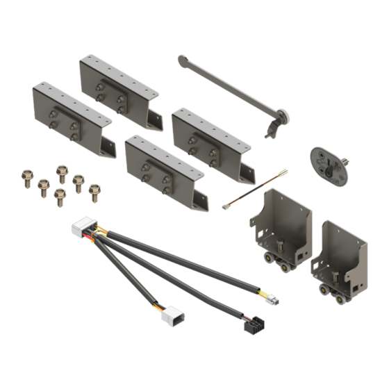
Remove and set aside the subassembly component kit (Fig.1) packaged with the bed frame. Remove and set aside the two stabilizer channel guides (Fig. 2) packaged with the bed frame. Fig. 1 Fig. 2 Page 3 Rev: 05.21.18 EuroLoft™ Bed Lift (Overhead) OEM... -
Page 4: Motor And Motor Bracket
Align the motor bolt holes with the holes in the motor bracket (Fig. 4A). Install the two M8-1.25 X 22mm hex head DIN 6921 steel serrated flange bolts through the motor bracket into the motor (Fig. 5A). Fig. 4 Fig. 5 Page 4 Rev: 05.21.18 EuroLoft™ Bed Lift (Overhead) OEM... -
Page 5: Power Controller
Align the ACS module holder with the ACS support bracket, then install the two previously removed screws (Fig. 9A) through the bracket and into the ACS module holder. Fig. 8 Fig. 9 Page 5 Rev: 05.21.18 EuroLoft™ Bed Lift (Overhead) OEM... -
Page 6: Stabilizer Guide Track Bracket And Roller Assembly
Remove the belt mounting assembly (Fig. 12) from the subassembly kit. Unscrew the nuts (Fig. 13C) and slide the belt plates (Fig. 13B) off the belt bracket (Fig. 13A) and set aside. Do this for all four belt brackets. Fig. 12 Fig. 13 Page 6 Rev: 05.21.18 EuroLoft™ Bed Lift (Overhead) OEM... - Page 7 15. Install the four previously removed M6 - 1.0mm hex flange nuts (Fig. 16A) onto the belt mounting bracket posts. Tighten the nuts to 25 ft-lbs. 16. Repeat steps 11-15 for the other three belts. Fig. 14 Fig. 15 Fig. 16 Page 7 Rev: 05.21.18 EuroLoft™ Bed Lift (Overhead) OEM...
-
Page 8: Stabilizer Channel Guides
If installing on a unit with wood backing in the wall, use a minimum size of #10 x 1" wood screws. The Euroloft switch can be installed in the wall of the unit next to the bed frame or if installing padded rails to the bed frame, in the padded rails. -
Page 9: Wiring Harness Connections
Install the switch harness connector end (Fig. 20F) to the back of the switch (Fig. 20K). Install the main wire harness motor connector (Fig. 20M) to the motor's female connector (Fig. 20N). Page 9 Rev: 05.21.18 EuroLoft™ Bed Lift (Overhead) OEM... -
Page 10: Wiring Diagram
Wiring Diagram Fig. 20 Power Controller ACS Module Main Wire Harness Switch Harness Back of Switch Battery Motor Page 10 Rev: 05.21.18 EuroLoft™ Bed Lift (Overhead) OEM... -
Page 11: Setting The Acs Stop Procedure
Press the UP arrow (Fig. 22A) and DOWN arrow (Fig. 22B) to run the bed lift system after each adjustment of the screw. If necessary, repeat this procedure until desired stop location is obtained. Page 11 Rev: 05.21.18 EuroLoft™ Bed Lift (Overhead) OEM... -
Page 12: Operation
Operation Always make sure that the EuroLoft Bed Lift path is clear of people, pets and objects before and during operation. Always keep away from the slide rails when the bed is being operated. Do not allow people or pets on bed while bed is in motion. -
Page 13: Manual Override
Fig. 23 Maintenance The EuroLoft Bed Lift system has been designed to require very little maintenance. To ensure the long life of your EuroLoft Bed Lift system, read and follow these few simple procedures: When the bed is raised, visually inspect the slide rail assemblies. - Page 14 The contents of this manual are proprietary and copyright protected by Lippert Components, Inc. (“LCI”). LCI prohibits the copying or dissemination of portions of this manual unless prior written consent from an authorized LCI representative has been provided. Any unauthorized use shall void any applicable warranty. The information contained in this manual is subject to change without notice and at the sole discretion of LCI. ...
Need help?
Do you have a question about the EuroLoft and is the answer not in the manual?
Questions and answers