
Related Manuals for Panasonic AFP7CPS4E


Summary of Contents for Panasonic AFP7CPS4E
- Page 1 Phone: 800.894.0412 - Fax: 888.723.4773 - Web: www.clrwtr.com - Email: info@clrwtr.com...
- Page 2 It could lead to an electric shock. Copyright / Trademarks -This manual and its contents are copyrighted. Panasonic -You may not copy this manual, in whole or part, without written consent of Industrial Devices SUNX Co., Ltd.
- Page 3 Introduction Thank you for buying a Panasonic product. Before you use the product, please carefully read the installation instructions and the users manual, and understand their contents in detail to use the product properly. Types of Manual There are different types of user's manual for the FP7 series, as listed below. Please refer to a relevant manual for the unit and purpose of your use.
-
Page 4: Table Of Contents
Table of Contents Table of Contents 1. Functions of Units and Restrictions on Combination ..1-1 Features and Functions of Units ............1-2 1.1.1 Functions of Units..................1-2 1.1.2 Types of Unit ...................1-3 1.1.3 Types of Cassette ...................1-3 1.1.4 Applications that can be Used in Each Port ..........1-3 Overview of Communication Functions.......... - Page 5 Table of Contents Wiring of COM Port Terminal Block............3-3 3.2.1 Suitable Wires and Tools ................3-3 3.2.2 Applicable Cable ..................3-4 3.2.3 Wiring Method ..................3-5 Wiring for CPU Unit (GT Power Supply and COM0 Port)....... 3-6 3.3.1 Handling of GT Power Supply Terminals..........3-6 3.3.2 Terminal Layouts and Examples of Wiring ..........3-6 Wiring for Communication Cassettes COM.1 to COM.4 Ports ....
- Page 6 Table of Contents Setting Communication Conditions ............5-3 5.2.1 Settings Using FPWIN GR7 (For CPU with built-in SCU).......5-3 5.2.2 Settings Using FPWIN GR7 (For Serial Communication Unit) ....5-4 6. PLC Link................6-1 Operation of PLC link MEWNET-W0............6-2 6.1.1 Overview of PLC Link Operation.............6-2 6.1.2 Operation of Link Relays and Link Registers ..........6-3 Configuration Required for PLC Link............
- Page 7 Table of Contents MEWTOCOL-COM Master Communication (RECV)......7-4 7.3.1 Read Data from an External Device ............7-4 7.3.2 RECV Instruction (When MEWTOCOL-COM is Used)......7-7 MEWTOCOL-COM Master Communication (SEND)......7-8 7.4.1 Write Data into an External Device ............7-8 7.4.2 SEND Instruction (When MEWTOCOL-COM is Used)......7-11 8.
- Page 8 Table of Contents 9.3.2 Contents of Sent Data ................9-6 9.3.3 GPSEND (General-Purpose Communication Sending Instruction) ..9-7 9.3.4 Precautions on Sending Data ..............9-8 Receiving Operation................9-9 9.4.1 Overview of Receiving Operation............9-9 9.4.2 Contents of Received Data ..............9-12 9.4.3 Precautions on Receiving Data.............9-12 9.4.4 Operations of the "Reception done copy"...
- Page 9 Table of Contents 11. Specifications ..............11-1 11.1 Communication Function Specifications..........11-2 11.1.1 CPU Unit Communication Specifications..........11-2 11.1.2 Extension Cassette Communication Specifications......11-4 11.2 MEWTOCOL-COM Format..............11-5 11.2.1 MEWTOCOL-COM Command Format ..........11-5 11.2.2 MEWTOCOL-COM Response Format..........11-7 11.3 MEWTOCOL7-COM Format..............11-9 11.3.1 MEWTOCOL7-COM Command Format ..........11-9 11.3.2 MEWTOCOL7 Response Format ............11-11 11.4 MODBUS RTU Format ...............
- Page 10 Table of Contents viii Phone: 800.894.0412 - Fax: 888.723.4773 - Web: www.clrwtr.com - Email: info@clrwtr.com...
-
Page 11: Functions Of Units And Restrictions On Combination
Functions of Units and Restrictions on Combination Phone: 800.894.0412 - Fax: 888.723.4773 - Web: www.clrwtr.com - Email: info@clrwtr.com... -
Page 12: Features And Functions Of Units
Functions of Units and Restrictions on Combination 1.1 Features and Functions of Units 1.1.1 Functions of Units CPU Unit Serial Communication Unit communication cassette can be communication attached. cassettes can be attached. COM.0 port is equipped as standard. (For 3-wire RS-232C) ... -
Page 13: Types Of Unit
1.1 Features and Functions of Units 1.1.2 Types of Unit Types of unit that can perform serial communication Communication ports that can be allocated Name Model no. COM.0 COM.1 COM.2 COM.3 COM.4 AFP7CPS4E ● ● ● CPU Unit AFP7CPS3E AFP7CPS3 ● ● ● ●... -
Page 14: Overview Of Communication Functions
Functions of Units and Restrictions on Combination 1.2 Overview of Communication Functions 1.2.1 PLC Link Functions (MEWNET-W0) Overview of function A system can be configured for the PLC link (MEWNET-W0). Exclusive internal relays “link relays (L)” and data registers “link registers (LD)” are shared between the connected PLCs. -
Page 15: Mewtocol Master/Slave Communication
1.2 Overview of Communication Functions 1.2.2 MEWTOCOL Master/Slave Communication Overview of function Execute communication using MEWTOCOL-COM, a communication protocol used by our PLC. In master communication, PLC executes communication by sending commands to devices that support MEWTOCOL, and receiving responses. Messages in accordance with the protocol are automatically generated by PLC. -
Page 16: Modbus Rtu Master/Slave Communication
Functions of Units and Restrictions on Combination 1.2.3 MODBUS RTU Master/Slave Communication Overview of function This is used for communicating with other devices that support the MODBUS RTU protocol. In master communication, communication is performed when the master unit sends instructions (command messages) to slave units and the slave unit returns responses (response messages) according to the instructions. -
Page 17: General-Purpose Communication
1.2 Overview of Communication Functions 1.2.4 General-Purpose Communication Overview of function General-purpose communication is used when PLC executes communication in accordance with the protocol of the partner device. Formulation and sending of command messages to the partner device, and reception processing of responses from the partner device, are performed by the user program. -
Page 18: Restrictions On Units Combination
Functions of Units and Restrictions on Combination 1.3 Restrictions on Units Combination 1.3.1 Restrictions on the Number of Installed Units There are following restrictions depending on units to be used. Unit type Number of installed units Remarks Serial Communication Unit Max. -
Page 19: Restrictions On Consumption Current
Including other units, the consumption current should be within the allowable capacity of a power supply unit. Unit's consumption current table (24 V) Consumption Product name Model number current (mA) 196k steps, Built-in Ethernet AFP7CPS4E 200 mA or less function CPU Unit 120k steps, Built-in Ethernet AFP7CPS3E 200 mA or less function... - Page 20 Functions of Units and Restrictions on Combination 1-10 Phone: 800.894.0412 - Fax: 888.723.4773 - Web: www.clrwtr.com - Email: info@clrwtr.com...
-
Page 21: Names And Functions Of Parts
Names and Functions of Parts Phone: 800.894.0412 - Fax: 888.723.4773 - Web: www.clrwtr.com - Email: info@clrwtr.com... -
Page 22: Names And Functions Of Parts
Names and Functions of Parts 2.1 Names and Functions of Parts 2.1.1 Communication Port of CPU Unit (In the above figure, a communication cassette is attached to the COM.1 and COM.2 ports.) Names and Functions of Parts (1) COM.1 and COM.2 ports Attach a separately sold communication cassette to use these ports. -
Page 23: Parts Names And Functions Of Serial Communication Unit
2.1 Names and Functions of Parts 2.1.2 Parts Names and Functions of Serial Communication Unit (In the above figure, two communication cassettes are attached.) Names and Functions of Parts (1) Operation monitor LEDs Display Description color Blue Lights when the power supply of the CPU unit is on. Lights when the configuration setting is incorrect, or a communication error occurs. - Page 24 Names and Functions of Parts Phone: 800.894.0412 - Fax: 888.723.4773 - Web: www.clrwtr.com - Email: info@clrwtr.com...
-
Page 25: Wiring The Com. Port
Wiring the COM. Port Phone: 800.894.0412 - Fax: 888.723.4773 - Web: www.clrwtr.com - Email: info@clrwtr.com... -
Page 26: Attaching A Communication Cassette
Wiring the COM. Port 3.1 Attaching a Communication Cassette 3.1.1 Attachment Instructions When an optional Communication Cassette is to be used, attach it in the following procedures. PROCEDURE 1. Using a flathead screwdriver, remove the cover on the side of the CPU unit. You will find four toggles. -
Page 27: Wiring Of Com Port Terminal Block
3.2 Wiring of COM Port Terminal Block 3.2 Wiring of COM Port Terminal Block 3.2.1 Suitable Wires and Tools A screw-down connection type for terminal block is used for the communication port. Use the following items for wiring. Suitable wires (strand wire) Size Nominal cross-sectional area AWG #28 to 16... -
Page 28: Applicable Cable
Wiring the COM. Port 3.2.2 Applicable Cable Use a cable as prescribed below. Suitable wires (strand wire): For RS-232C / RS-422 communication Conductor Insulator Sample Classifi- Cross-sectional Cable Resistance appropriate Thick- cation view diam. Size value Material cable ness (at 20°C) Cover Shield... -
Page 29: Wiring Method
3.2 Wiring of COM Port Terminal Block 3.2.3 Wiring Method Wiring method (1) Remove a portion of the wire’s insulation. (2) Insert wire into terminal hole until it stops. Tighten screw clockwise to fix wire in place. (The tightening torque: 0.22 to 0.25 N·m (2.3 to 2.5 kgf·cm)) ... -
Page 30: Wiring For Cpu Unit (Gt Power Supply And Com0 Port)
Wiring the COM. Port 3.3 Wiring for CPU Unit (GT Power Supply and COM0 Port) 3.3.1 Handling of GT Power Supply Terminals GT power supply terminals can be used as power supply terminals for the GT series of our programmable displays. - Page 31 3.3 Wiring for CPU Unit (GT Power Supply and COM0 Port) Example of wiring (in the case of GT02 5V DC type) FP7 CPU unit GT02 / GT02L series COM.0 port terminal / GT power supply terminal 5V DC type Terminal Terminal Signal name...
-
Page 32: Wiring For Communication Cassettes Com.1 To Com.4 Ports
Wiring the COM. Port 3.4 Wiring for Communication Cassettes COM.1 to COM.4 Ports 3.4.1 Communication Cassette AFP7CCS1 (RS-232C, 1-Channel Insulated Type) Terminal layout Terminal LED part Terminal Functions Signal Ports that can be Symbol part that can be direction allocated Symbol allocated... -
Page 33: Communication Cassette Afp7Ccs2 (Rs-232C, 2-Channel Insulated Type)
3.4 Wiring for Communication Cassettes COM.1 to COM.4 Ports 3.4.2 Communication Cassette AFP7CCS2 (RS-232C, 2-channel insulated type) Setting of Application Switch Applications for use can be switched using a switch on the backplane for Communication Cassette AFP7CCS2. Settings can be confirmed with LED lamps at the front of the cassette. 3-wire 2-channel RS-232C 5-wire 1-channel RS-232C (RS/CS controlled) Phone: 800.894.0412 - Fax: 888.723.4773 - Web: www.clrwtr.com - Email: info@clrwtr.com... - Page 34 Wiring the COM. Port Terminal layout (in the setting of 3-wire 2-channel RS-232C) Terminal LED part Terminal Functions Signal Ports that can be Symbol part that can be direction allocated Symbol allocated in the software PLC → SD: Sent Data External device PLC ←...
- Page 35 3.4 Wiring for Communication Cassettes COM.1 to COM.4 Ports Terminal layout (in the setting of 5-wire 1-channel RS-232C RS/CS controlled) Terminal LED part Terminal Functions Signal Ports that can be Symbol part that can be direction allocated Symbol allocated in the software PLC →...
-
Page 36: Communication Cassette Afp7Ccm1 (Rs-422 / Rs-485, 1-Channel Insulated Type)
Wiring the COM. Port 3.4.3 Communication Cassette AFP7CCM1 (RS-422 / RS-485, 1-Channel Insulated Type) Setting of application switch Applications for use can be switched using a switch on the backplane for Communication Cassette AFP7CCM1. Settings can be confirmed with LED lamps at the front of the cassette. ... - Page 37 3.4 Wiring for Communication Cassettes COM.1 to COM.4 Ports Terminal layout (in the setting of RS-485) Terminal LED part Terminal Functions that can Signal Ports that can be Symbol part be allocated direction allocated Symbol in the software + / S Transmission line (+) - / S Transmission line (-)
- Page 38 Wiring the COM. Port Terminal layout (in the setting of RS-422) Terminal LED part Terminal Functions that Signal Ports that can be Symbol part can be direction allocated Symbol allocated in the software PLC → + / S Sent Data (+) External device PLC →...
-
Page 39: Communication Cassette Afp7Ccm2 (Rs-422 / Rs-485, 2-Channel Insulated Type)
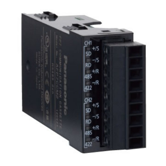
3.4 Wiring for Communication Cassettes COM.1 to COM.4 Ports 3.4.4 Communication Cassette AFP7CCM2 (RS-422 / RS-485, 2-Channel Insulated Type) Setting of application switch Applications for use can be switched using a switch on the backplane for Communication Cassette AFP7CCM2. Settings can be confirmed with LED lamps at the front of the cassette. ... - Page 40 Wiring the COM. Port Terminal layout (in the setting of RS-485) Terminal LED part Terminal Functions that can Signal Ports that can Symbol part be allocated direction be allocated Symbol in the software + / S Transmission line (+) - / S Transmission line (-) COM.1...
- Page 41 3.4 Wiring for Communication Cassettes COM.1 to COM.4 Ports Example of wiring (in the setting of RS-485) AFP7CCM2 Transmission line 1 Partner 1 Terminal Terminal Terminal Signal name Signal name Functions part symbol Transmission line (+) + / S Transmission line 1 (+) - / S Transmission line 1 (-)
- Page 42 Wiring the COM. Port Terminal layout (in the setting of RS-422) Terminal LED part Terminal Functions that Signal direction Ports that can be Symbol part can be allocated allocated Symbol in the software PLC → External device + / S Sent Data (+) PLC →...
-
Page 43: Communication Cassette Afp7Ccs1M1
3.4 Wiring for Communication Cassettes COM.1 to COM.4 Ports 3.4.5 Communication Cassette AFP7CCS1M1 (RS-232C 1-Channel + RS-485 1-Channel Insulated Type) Settings for termination resistance selector switch A termination resistance selector switch is located on the RS-485 side of the surface of Communication Cassette AFP7CCS1M1. - Page 44 Wiring the COM. Port Example of wiring AFP7CCS1M1 RS-485 Partner 1 Terminal Terminal Signal name Functions Terminal Signal name part symbol Transmission line (+) + / S Transmission line (+) Transmission line (-) - / S Transmission line (-) + / R Transmission line (+) RS-485 Partner 2...
-
Page 45: I/O Allocation
I/O Allocation Phone: 800.894.0412 - Fax: 888.723.4773 - Web: www.clrwtr.com - Email: info@clrwtr.com... -
Page 46: Input/Output Signals Used For Communication
I/O Allocation 4.1 Input/Output Signals Used for Communication 4.1.1 I/O Allocation of CPU Unit Input signal Effective Input Communication Name Description operation signal port mode For COM.1 Port General- When the unit completes the data reception, General- purpose it turns on (1). For COM.2 Port communication purpose... - Page 47 4.1 Input/Output Signals Used for Communication Output signal Effective Output Communication Name Description operation signal port mode For COM.1 Port MEWTOCOL Reports the results of sending in master communication or general-purpose MODBUS-RTU For COM.2 Port Sending done communication. General- result Normal completion: 0, Abnormal completion: purpose...
-
Page 48: I/O Allocation Of Serial Communication Unit
I/O Allocation 4.1.2 I/O Allocation of Serial Communication Unit Input signal Effective Input Communication Name Description operation signal port mode For COM.1 Port General- When the unit completes the data reception, purpose General- For COM.2 Port it turns on (1). communication purpose Waiting for data reception: 0, Reception... - Page 49 4.1 Input/Output Signals Used for Communication Output signal Effective Output Communication Name Description operation signal port mode For COM.1 Port MEWTOCOL Reports the results of sending in master communication or general-purpose MODBUS-RTU For COM.2 Port Sending done communication. General- For COM.3 Port result Normal completion: 0, Abnormal completion:...
-
Page 50: Registration In I/O Map
I/O Allocation 4.2 Registration in I/O Map 4.2.1 Settings Using FPWIN GR7 (For CPU with built-in SCU) For the CPU with built-in SCU, there is no need to set with FPWIN GR7 because the following fixed areas are allocated. No. - Page 51 4.2 Registration in I/O Map 5. Double-click Slot No. 1 in the "I/O map" dialog box. The "Unit selection [Slot No. 1]" dialog box is displayed. 6. Select "Communications" for Unit type, and select "SCU unit" for Unit name, and press [OK] button. "SCU unit"...
- Page 52 I/O Allocation Phone: 800.894.0412 - Fax: 888.723.4773 - Web: www.clrwtr.com - Email: info@clrwtr.com...
-
Page 53: Setting And Confirming Communication Conditions
Setting and Confirming Communication Conditions Phone: 800.894.0412 - Fax: 888.723.4773 - Web: www.clrwtr.com - Email: info@clrwtr.com... -
Page 54: Setting Applications And Communication Conditions
Setting and Confirming Communication Conditions 5.1 Setting Applications and Communication Conditions 5.1.1 Applications to be Set for Each Port Available functions for each communication port Allocated communication port Communication function to be used COM.0 COM.1 COM.2 COM.3 COM.4 ● PLC link ●... -
Page 55: Setting Communication Conditions
5.2 Setting Communication Conditions 5.2 Setting Communication Conditions 5.2.1 Settings Using FPWIN GR7 (For CPU with built-in SCU) Applications and communication conditions for each communication port should be set using the tool software FPWIN GR7. PROCEDURE 1. From the menu bar, select "Option" > "FP7 Configuration". The "FP7 Configuration"... -
Page 56: Settings Using Fpwin Gr7 (For Serial Communication Unit)
Setting and Confirming Communication Conditions 5.2.2 Settings Using FPWIN GR7 (For Serial Communication Unit) Applications and communication conditions for each communication port should be set using the tool software FPWIN GR7. The explanation below shows the case that the serial communication unit is registered in the slot number 1. -
Page 57: Plc Link
PLC Link Phone: 800.894.0412 - Fax: 888.723.4773 - Web: www.clrwtr.com - Email: info@clrwtr.com... -
Page 58: Operation Of Plc Link Mewnet-W0
PLC Link 6.1 Operation of PLC link MEWNET-W0 6.1.1 Overview of PLC Link Operation “Link relays (L)” and data registers “link registers (LD)” are shared between the connected PLCs. If the link relay contact for one PLC goes on, the same link relay also goes on in each of the other PLCs connected to the network. -
Page 59: Operation Of Link Relays And Link Registers
6.1 Operation of PLC link MEWNET-W0 6.1.2 Operation of Link Relays and Link Registers Link relay If the link relay L0 in unit No.1 is turned on, the status change is fed back to the link relay L0 with the same number in other units, and R0 in the other units is output. RS485 No.2 Link register No.3 Link register... -
Page 60: Configuration Required For Plc Link
PLC Link 6.2 Configuration Required for PLC Link 6.2.1 Setup Procedure (For CPU with built-in SCU) In order to use the PLC link function, setting of communication conditions and allocation of memories are required. Settings should be performed by the programming tool FPWIN GR7. PROCEDURE 1. -
Page 61: Setup Procedure (For Serial Communication Unit)
6.2 Configuration Required for PLC Link 6.2.2 Setup Procedure (For Serial Communication Unit) In order to use the PLC link function, setting of communication conditions and allocation of memories are required. Settings should be performed by the programming tool FPWIN GR7. ... -
Page 62: List Of Setting Items
PLC Link 6.2.3 List of Setting Items List of setting items (COM1 settings) Settings when the PLC link Setting items Remark function is used Communication mode PLC link Set a specific station no. for PLC to be Station no. 1 - 16 connected to the PLC link. -
Page 63: Setting Items For Plc Link
6.3 Setting Items for PLC Link 6.3 Setting Items for PLC Link 6.3.1 Station No. Setting In the PLC link where multiple PLCs are connected to the transmission line, station no. should be set to identify each PLC. Station nos. are the numbers to identify the different PLCs on the same network. The same number must not be used for more than one PLC on the same network. -
Page 64: Memory Block Numbers For Link Relays And Link Registers To Be Used6-8
PLC Link 6.3.3 Memory Block Numbers for Link Relays and Link Registers to be Used The memory area of link relays and link registers are divided into the area for PLC link 0 and the area for PLC link 1, which can respectively use up to 1024 link relay points (64 words) and up to 128 link register words. -
Page 65: Starting No. For Link Relay Send Area And Sending Size
6.3 Setting Items for PLC Link 6.3.5 Starting No. for Link Relay Send Area and Sending Size The memory areas for link relays are divided into send areas and receive areas. The link relays are transmitted from the send area to the receive area of a different PLC. Link relays with the same numbers as those on the sending side must exist in the receive area on the receiving side. -
Page 66: Starting No. For Link Register Send Area And Sending Size
PLC Link 6.3.6 Starting No. for Link Register Send Area and Sending Size The memory areas for link registers are divided into send areas and receive areas. The link registers are sent from the send area to the receive area of a different PLC. Link registers with the same numbers as those on the sending side must exist in the receive area on the receiving side. - Page 67 6.3 Setting Items for PLC Link In the example shown below, there is an area between No. 2 and No. 3 link relays which is overlapped, and this will cause an error, so that communication cannot be carried out. The allocations shown below are not possible, neither for link relays nor for link registers.
-
Page 68: Plc Link Response Time
PLC Link 6.4 PLC Link Response Time 6.4.1 Response Time of 1 Transmission Cycle The maximum value for the transmission time (T) of one cycle can be calculated using the following formula. Calculation formula (1) Ts (transmission time per station) Calculation Ts = Scan time + Tpc (PLC link sending time) formula... - Page 69 6.4 PLC Link Response Time Example of calculation Response time of 1 Condition Calculation process transmission cycle 16 units connected to the link; no Ttx = 0.096 station yet to be added Each Pcm = 23 + (4 + 8) × 4 = 71 bytes Where Max.
-
Page 70: Response Time When There Is A Station Yet To Be Added
PLC Link 6.4.2 Response Time When There is a Station Yet to be Added If there are stations that have not been added to the link, the Tlk time (link addition processing time) increases, and with this the transmission cycle time will be longer. NOTE ... - Page 71 MEWTOCOL Master/Slave Communication Phone: 800.894.0412 - Fax: 888.723.4773 - Web: www.clrwtr.com - Email: info@clrwtr.com...
-
Page 72: Mewtocol Master/Slave Communication
MEWTOCOL Master/Slave Communication 7.1 Configuration 7.1.1 Setting Communication Conditions Configuration Setting items Default Specification range Remark MEWTOCOL-COM Communication MEWTOCOL- Master communication is not mode possible using MEWTOCOL7. MEWTOCOL7-COM Set a specific station no. for PLC to MEWTOCOL-COM: 0 - 99 be connected to the PLC link. -
Page 73: List Of Mewtocol / Mewtocol7 Supporting Commands
7.2 List of MEWTOCOL / MEWTOCOL7 Supporting Commands 7.2 List of MEWTOCOL / MEWTOCOL7 Supporting Commands 7.2.1 List of MEWTOCOL Commands Commands to be used Type of instruction Code Description Reads ON/OFF status of contact. (RCS) - Specifies only one point. Read contact area (RCP) - Specifies multiple contacts. -
Page 74: Mewtocol-Com Master Communication (Recv)
MEWTOCOL Master/Slave Communication 7.3 MEWTOCOL-COM Master Communication (RECV) 7.3.1 Read Data from an External Device Instructions In master communication, PLC has the sending right, and executes communication by sending commands to devices that support MEWTOCOL, and receiving responses. Messages in accordance with the protocol are automatically generated by PLC. In the user program, reading and writing can be done simply by specifying the station no. - Page 75 7.3 MEWTOCOL-COM Master Communication (RECV) Timing chart Master communication Conditions to enable execution of RECV Clear to send flag instruction (XC, XD, XE, XF) Clear to send flag (XC, XD, XE, XF): ON Confirm ON Sending active flag (YC, YD, YE, YF): OFF Confirm OFF Master communication Sending active flag...
- Page 76 MEWTOCOL Master/Slave Communication KEY POINTS Specify the port targeted for communication, using UNITSEL instruction immediately before SEND/RECV instruction. Master communication is only valid when MEWTOCOL or MODBUS is selected. Confirm that the "Master communication Clear to send flag" (XC - XF) for the targeted channel is ON, and execute SEND/RECV instruction.
-
Page 77: Recv Instruction (When Mewtocol-Com Is Used)
7.3 MEWTOCOL-COM Master Communication (RECV) 7.3.2 RECV Instruction (When MEWTOCOL-COM is Used) Instruction format Items Settings Setting range Specify the operation unit. US / SS Specify the partner station no. 1 - 99 Specify the device initial address of the source node data area in the partner 0 - 99999 node. -
Page 78: Mewtocol-Com Master Communication (Send)
MEWTOCOL Master/Slave Communication 7.4 MEWTOCOL-COM Master Communication (SEND) 7.4.1 Write Data into an External Device Instructions In master communication, PLC has the sending right, and executes communication by sending commands to devices that support MEWTOCOL, and receiving responses. Messages in accordance with the protocol are automatically generated by PLC. In the user program, reading and writing can be done simply by specifying the station no. - Page 79 7.4 MEWTOCOL-COM Master Communication (SEND) Timing chart Master communication Conditions to enable execution of SEND Clear to send flag instruction (XC, XD, XE, XF) Confirm ON Clear to send flag (XC, XD, XE, XF): ON Sending active flag (YC, YD, YE, YF): OFF Master communication Confirm OFF Sending active flag...
- Page 80 MEWTOCOL Master/Slave Communication KEY POINTS Specify the port targeted for communication, using UNITSEL instruction immediately before SEND/RECV instruction. Master communication is only valid when MEWTOCOL or MODBUS is selected. Confirm that the "Master communication Clear to send flag" (XC - XF) for the targeted channel is ON, and execute SEND/RECV instruction.
-
Page 81: Send Instruction (When Mewtocol-Com Is Used)
7.4 MEWTOCOL-COM Master Communication (SEND) 7.4.2 SEND Instruction (When MEWTOCOL-COM is Used) Instruction format Setting Settings Setting range items Specify the operation unit. US / SS Specify the header of the source node data area. (Note 1) 1 - 507 words Specify the No. - Page 82 MEWTOCOL Master/Slave Communication 7-12 Phone: 800.894.0412 - Fax: 888.723.4773 - Web: www.clrwtr.com - Email: info@clrwtr.com...
- Page 83 MODBUS RTU Master/Slave Communication Phone: 800.894.0412 - Fax: 888.723.4773 - Web: www.clrwtr.com - Email: info@clrwtr.com...
-
Page 84: Modbus Rtu Master/Slave Communication
MODBUS RTU Master/Slave Communication 8.1 Configuration 8.1.1 Setting Communication Conditions Configuration Setting items Default Specification range Remark MEWTOCOL- Communication mode MODBUS-RTU Specify "MODBUS-RTU". Set a specific station no. for PLC to be connected to the PLC link. Set a Station no. -
Page 85: List Of Modbus Rtu Supported Commands
8.2 List of MODBUS RTU Supported Commands 8.2 List of MODBUS RTU Supported Commands 8.2.1 List of MODBUS Function Codes Table of supported commands Remarks FP7 supported Code Name (MODBUS) Name (Reference No.) functions ● Read Coil Status Read Y and R Coils ●... -
Page 86: Modbus Rtu Master Communication (Recv)
MODBUS RTU Master/Slave Communication 8.3 MODBUS RTU Master Communication (RECV) 8.3.1 Read Data from an External Device Instructions In master communication, PLC has the sending right, and executes communication by sending commands to devices that support MODBUS-RTU, and receiving responses. Messages in accordance with the protocol are automatically generated by PLC. - Page 87 8.3 MODBUS RTU Master Communication (RECV) Timing chart Master communication Conditions to enable execution of RECV Clear to send flag instruction (XC, XD, XE, XF) Clear to send flag (XC, XD, XE, XF): ON Confirm ON Sending active flag (YC, YD, YE, YF): OFF Master communication Confirm OFF Sending active flag...
- Page 88 MODBUS RTU Master/Slave Communication KEY POINTS Specify the port targeted for communication, using UNITSEL instruction immediately before SEND/RECV instruction. Master communication is only valid when MEWTOCOL or MODBUS is selected. Confirm that the "Master communication Clear to send flag" (XC - XF) for the targeted channel is ON, and execute SEND/RECV instruction.
-
Page 89: Recv Instruction (Modbus Function Code Specified Type)
8.3 MODBUS RTU Master Communication (RECV) 8.3.2 RECV Instruction (MODBUS Function Code Specified Type) Instruction format Operand Items Settings Setting range Specify the operation unit. US / SS Specify the MODBUS function codes and partner station no. to be used. (Note 1) (Note 2) Higher Two hexadecimal digits that indicate the MODBUS H1 - H4 (1 - 4) -
Page 90: Recv Instruction (Modbus Function Code Unspecified Type)
MODBUS RTU Master/Slave Communication 8.3.3 RECV Instruction (MODBUS Function Code Unspecified Type) Instruction format Operand Items Settings Setting range Specify the operation unit. US / SS Specify the partner station no. H1 - HF7 (1 - 247) H0 - HFFFF (0 - 65535) Specify the device initial address of the source node data area in the partner node. -
Page 91: Modbus Rtu Master Communication (Send)
8.4 MODBUS RTU Master Communication (SEND) 8.4 MODBUS RTU Master Communication (SEND) 8.4.1 Write Data into an External Device Instructions In master communication, PLC has the sending right, and executes communication by sending commands to devices that support MODBUS-RTU, and receiving responses. Messages in accordance with the protocol are automatically generated by PLC. - Page 92 MODBUS RTU Master/Slave Communication Timing chart Master communication Conditions to enable execution of SEND Clear to send flag instruction (XC, XD, XE, XF) Confirm ON Clear to send flag (XC, XD, XE, XF): ON Sending active flag (YC, YD, YE, YF): OFF Master communication Confirm OFF Sending active flag...
- Page 93 8.4 MODBUS RTU Master Communication (SEND) KEY POINTS Specify the port targeted for communication, using UNITSEL instruction immediately before SEND/RECV instruction. Master communication is only valid when MEWTOCOL or MODBUS is selected. Confirm that the "Master communication Clear to send flag" (XC - XF) for the targeted channel is ON, and execute SEND/RECV instruction.
-
Page 94: Send Instruction (Modbus Function Code Specified Type)
MODBUS RTU Master/Slave Communication 8.4.2 SEND Instruction (MODBUS Function Code Specified Type) Instruction format Operand Items Settings Setting range Specify the operation unit. US / SS Specify the header of the source node data area. (Note 1) 1 - 127 words Specify the No. -
Page 95: Send Instruction (Modbus Function Code Unspecified Type)
8.4 MODBUS RTU Master Communication (SEND) 8.4.3 SEND Instruction (MODBUS Function Code Unspecified Type) Instruction format Operand Items Settings Setting range Specify the operation unit. US / SS Specify the header of the source node data area. (Note 1) Specify the No. - Page 96 MODBUS RTU Master/Slave Communication 8-14 Phone: 800.894.0412 - Fax: 888.723.4773 - Web: www.clrwtr.com - Email: info@clrwtr.com...
-
Page 97: General-Purpose Communication
General-Purpose Communication Phone: 800.894.0412 - Fax: 888.723.4773 - Web: www.clrwtr.com - Email: info@clrwtr.com... -
Page 98: Operation Of General-Purpose Communication
General-Purpose Communication 9.1 Operation of General-Purpose Communication 9.1.1 Read Data from an External Device Read data from a partner device In general-purpose communication, communication is executed by sending commands that suit the partner device, and receiving responses. Command messages are sent by formulating a data table for message in accordance with the protocol, on the given data register, and subsequently executing GPSEND instruction. -
Page 99: Configuration
9.2 Configuration 9.2 Configuration 9.2.1 Setting Communication Conditions Configuration Setting items Default Specification range Remark Communication General-purpose Specify "general-purpose MEWTOCOL-COM mode communication communication". Station no. 1 - 999 Settings are not necessary. 300 / 600 / 1200 / 2400 / 4800 / 9600 / 19200 / Baud rate 9600... -
Page 100: Sending Operation
General-Purpose Communication 9.3 Sending Operation 9.3.1 Overview of Sending Operation Instructions Sending in the general-purpose communication is performed by formulating a data table for sending on the given operation memory, and subsequently executing GPSEND instruction. External device Send message/data ABCDE (CR) ・・・・・・・・... - Page 101 9.3 Sending Operation Timing chart Data in the table [S] specified by GPSEND instruction are sent, in ascending order from lower bytes. During the sending process, the "General-purpose communication Sending active flag" (Y8, Y9, YA, YB) turns ON. The flag is turned OFF when sending is completed. (The flag does not turn off right after the execution of the instruction.
-
Page 102: Contents Of Sent Data
General-Purpose Communication KEY POINTS Specify the port targeted for communication, using UNITSEL instruction immediately before GPSEND instruction. Maintain the ON conditions for GPSEND instruction until sending is completed and the general-purpose communication sending active flag (Y8, Y9, YA, YB) turns OFF. 9.3.2 Contents of Sent Data Strings data sent by the GPSEND instruction are converted into ASCII text and saved in a given data register. -
Page 103: Gpsend (General-Purpose Communication Sending Instruction)
9.3 Sending Operation 9.3.3 GPSEND (General-Purpose Communication Sending Instruction) Instruction format Items Settings Setting range Specify the operation unit. US / SS (Note 1) Specify the header of the source node data area. (Note 2) 1 to 4094, -1 to -4096 Specify the No. -
Page 104: Precautions On Sending Data
General-Purpose Communication 9.3.4 Precautions on Sending Data Procedures when the end code is not added in the sending process When you do not wish to add the terminator (end code) in the sending process, use a negative value for specifying the No. of sent bytes. R101 R100 GPSEND execution conditions... -
Page 105: Receiving Operation
9.4 Receiving Operation 9.4 Receiving Operation 9.4.1 Overview of Receiving Operation Instructions In the general-purpose communication mode, data received from the partner device are saved in eight reception buffers for each COM port. When the GPRECV instruction is executed in a user program, data in the reception buffer can be copied into a given operation memory. - Page 106 General-Purpose Communication I/O allocation (CPU Unit) COM port no. Name Explanation General-purpose Turns ON when the receiving process is completed in communication Reception the general-purpose communication mode. done flag Turns ON when the GPRECV instruction is executed General-purpose and the received data have been copied into the communication Reception specified operation memory.
- Page 107 9.4 Receiving Operation Saving method for received data When data are saved in a given data register from the reception buffer, based on GPRECV instruction, the data are saved in the following manner. Saves the received No. of bytes. DT200 H32(2) H31(1)
-
Page 108: Contents Of Received Data
General-Purpose Communication 9.4.2 Contents of Received Data When data are copied into a given data register, based on GPRECV instruction, the data are saved in the following manner. Example: The data “12345 CR” is transmitted from a device with RS-232C device. ... -
Page 109: Operations Of The "Reception Done Copy" Flag And Multiplex Reception
9.4 Receiving Operation 9.4.4 Operations of the "Reception done copy" flag and multiplex reception Operation and function of the "reception done copy" flag (X4, X5, X6, X7) The "reception done copy" flag (X4, X5, X6, X7) turns ON when the GPRECV instruction is executed and data are copied from the reception buffer to the specified operation memory, and turns OFF when the END instruction is executed. -
Page 110: Gprecv (General-Purpose Communication Receiving Instruction)
General-Purpose Communication 9.4.5 GPRECV (General-Purpose Communication Receiving Instruction) Instruction format Setting Settings Setting range items Specify the operation unit. US / SS Specify the initial address of the data area to save the received data. (Note 1) Specify the final address of the data area to save the received data. (Note 2) (Note 1): Device that can be specified for D1 are: WX, WY, WR, WL, DT, LD. -
Page 111: Sending/Receiving Flag Operation
9.5 Sending/Receiving Flag Operation 9.5 Sending/Receiving Flag Operation 9.5.1 No Header (Start Code), Terminator (End Code) "CR": The “reception done” flag, the “sending active” flag, the GPSEND instruction, and the GPRECV instruction are related as follows: Data received from external device Stored receive bu ffer... -
Page 112: Start Code "Stx", End Code "Etx
General-Purpose Communication After GPSEND instruction is executed, dual sending to the same port is not possible until the "sending General-purpose communication Sending active flag" (Y8, Y9, YA, YB) turns OFF. The "General-purpose communication Sending active flag" (Y8, Y9, YA, YB) turns OFF in instruction execution in the next scan or later following completion of data sending. - Page 113 9.5 Sending/Receiving Flag Operation However, if the code STX is added in the middle of the data, the data are saved from the beginning of the reception buffer. Sending process: Sending done flag and GPSEND instruction are related as follows: Transmitted data send buffer...
- Page 114 General-Purpose Communication 9-18 Phone: 800.894.0412 - Fax: 888.723.4773 - Web: www.clrwtr.com - Email: info@clrwtr.com...
-
Page 115: Troubleshooting
Troubleshooting Phone: 800.894.0412 - Fax: 888.723.4773 - Web: www.clrwtr.com - Email: info@clrwtr.com... -
Page 116: Self-Diagnostic Function
Troubleshooting 10.1 Self-diagnostic Function 10.1.1 CPU Unit’s Operation Monitor LED The CPU unit has a self-diagnostic function which identifies errors and stops operation if necessary. Indications concerning self-diagnosis are as follows. LED indications concerning self-diagnostic errors LED indications on the CPU unit Operation Description PROG... -
Page 117: Serial Communication Unit's Operation Monitor Led
10.1 Self-diagnostic Function 10.1.3 Serial Communication Unit's Operation Monitor LED The serial communication unit has a self-diagnostic function which indentifies errors. Indications concerning self-diagnosis are as follows. LED indications concerning self-diagnostic errors Status Status Countermeasures indication Parameter setting error or Refer to10.2 What to DO If an Error transmission/reception error Occurs... -
Page 118: What To Do If An Error Occurs (For Each Communication Mode)
Troubleshooting 10.2 What to DO If an Error Occurs (For Each Communication Mode) 10.2.1 When Using PLC Link Function What to do If an error occurs Situation Contents to check Confirmation method Check if the communication cassette Is a communication cassette attached? is attached firmly. -
Page 119: When Using General-Purpose Communication Function
10.2 What to DO If an Error Occurs (For Each Communication Mode) 10.2.3 When Using General-purpose Communication Function What to do if an error occurs Situation Contents to check Confirmation method Check if the communication block is Is a communication cassette attached? installed firmly. -
Page 120: Checking Status With Pmget Instruction
Troubleshooting 10.3 Checking Status with PMGET Instruction 10.3.1 Specifications of PMGET Instruction Confirmation of error information Describe UNITSEL instruction immediately before PMGET instruction, and specify the slot and port numbers of the unit to be read. Specify the type of data to be read (parameter or monitor information) for operand S1 of PMGET instruction. - Page 121 10.3 Checking Status with PMGET Instruction Operand Parameter Range Settings [D+8] Header STX U0, U1 U0: Disable, U1: Enable [D+9] Terminator setting U0 to U3 U0: cR, U1: cR+Lf, U2: Time, U3: ETX U0: For 32 bits Terminator [D+10] U0 to 10000 Effective time = Un x 0.01 ms (Effective only when the judgement time terminator setting is Time)
- Page 122 Troubleshooting SCU COM port operation status monitor information Operand Monitor Range Settings information U0: MEWTOCOL-COM U1: MEWTOCOL7-COM Operation mode U2: MODBUS-RTU U8: General-purpose communication U9: PLC link U 0:No communication cassette Communication U232 U 232:RS-232C [D+1] cassette detection U422 U 422:RS-422 U485 U 485:RS-485...
-
Page 123: Clearing Errors Using User Programs
10.4 Clearing Errors Using User Programs 10.4 Clearing Errors Using User Programs 10.4.1 Clearing Errors Using User Programs Each error can be cleared by user programs. Refer to error codes, correct error factors, and clears the errors. Clearing unit by UCLR instruction ... - Page 124 Troubleshooting 10-10 Phone: 800.894.0412 - Fax: 888.723.4773 - Web: www.clrwtr.com - Email: info@clrwtr.com...
-
Page 125: Specifications
Specifications Phone: 800.894.0412 - Fax: 888.723.4773 - Web: www.clrwtr.com - Email: info@clrwtr.com... -
Page 126: Communication Function Specifications
Specifications 11.1 Communication Function Specifications 11.1.1 CPU Unit Communication Specifications USB port (for tool software) Items Description Standard USB2.0 FULL SPEED Communication function MEWTOCOL-COM (slave), MEWTOCOL7-COM (slave) COM0 Port Items Description Interface 3-wire 1-channel RS-232C Transmission distance 15 m (Note 1) Baud rate 300, 600,1200, 2400, 4800, 9600, 19200, 38400, 57600, 115200, 230400 bit / s... - Page 127 11.1 Communication Function Specifications LAN port Items Description Interface 100BASE-TX / 10BASE-T Baud rate 100 Mbps, 10 Mbps auto-negotiation (Note 1) Transmission system Baseband Max. segment length 100 m (Note 2) Communication cable UTP (Category 5) 100BASE-TX: 2 segments Max.
-
Page 128: Extension Cassette Communication Specifications
Specifications 11.1.2 Extension Cassette Communication Specifications COM1 Port / COM2 Port Description Items AFP7CCS1 AFP7CCS2 AFP7CCM1 AFP7CCM2 AFP7CCS1M1 3-wire 3-wire 1-channel 3-wire 2-channel RS-232C 1-channel 2-channel Interface 1-channel RS-232C RS-422/RS485 RS-422/RS485 1-channel RS-232C (Note 2) (Note 3) (Note 2) (Note 3) (Note 1) RS485 (Note 3) RS-232C:... -
Page 129: Mewtocol-Com Format
11.2 MEWTOCOL-COM Format 11.2 MEWTOCOL-COM Format 11.2.1 MEWTOCOL-COM Command Format Command message (1) Header (start code) Commands must always have a “%” (ASCII code: H25) or a “<” (ASCII code: H3C) at the beginning of a message. (2) Station no. ... - Page 130 Specifications NOTES The method for writing text segments in the message varies depending on the type of command. When the message to be sent contains a large number of characters, send the command divided in several times. When the message contains a large number of characters, the response is sent divided in several times.
-
Page 131: Mewtocol-Com Response Format
11.2 MEWTOCOL-COM Format 11.2.2 MEWTOCOL-COM Response Format Response message After PLC receives a command, it returns the processing result. (1) Header (start code) A “%” (ASCII code: H25) or “<” (ASCII code: H3C) must be at the beginning of a message. ... - Page 132 Specifications NOTES If no response is returned, the communication format may not be correct, or the command may not have arrived at the PLC, or the PLC may not be functioning. Check to make sure all of the communication specifications (e.g.
-
Page 133: Mewtocol7-Com Format
11.3 MEWTOCOL7-COM Format 11.3 MEWTOCOL7-COM Format 11.3.1 MEWTOCOL7-COM Command Format Command message (1) Header (start code) (3) Frame No. (2) Station no. of the receiver (4) Text (to be specified in accordance with the type of command) > Command name Command code value Command ID code (6) Terminator (end code) - Page 134 Specifications (5) Check code This is a CRC (Cyclic Redundancy Check) to detect errors using a generating polynomial of hamming codes. This should be created so that it targets all of the text data from the header to the last text character.
-
Page 135: Mewtocol7 Response Format
11.3 MEWTOCOL7-COM Format 11.3.2 MEWTOCOL7 Response Format Response message (1) Header (start code) (2) Station no. of the receiver (3) Frame No. (4) Text (to be specified in accordance with the type of command) > Command name (data area read) Command code value Response code (normal status: $, abnormal status: !) Data (normal status: read data, abnormal... - Page 136 Specifications (5) Check code This is a CRC (Cyclic Redundancy Check) to detect errors using a generating polynomial of hamming codes. This should be created so that it targets all of the text data from the header to the last text character.
-
Page 137: Modbus Rtu Format
11.4 MODBUS RTU Format 11.4 MODBUS RTU Format 11.4.1 MODBUS RTU Command Format MODBUS RTU command format START ADDRESS FUNCTION DATA CRC CHECK 3.5-character 8 bits 8 bits n*8 bits 16 bits 3.5-character time time ADDRESS 8 bits, 0 to 247 (decimal) (station no.) (Note) 0 = Broadcast address FUNCTION... -
Page 138: Modbus Rtu Response Format
Specifications 11.4.2 MODBUS RTU Response Format Response in normal status The same message as a command is returned and for a loop back test. A part of a command message (6 bytes from the beginning) is returned for multiple write command. - Page 139 Record of changes Manual No. Date Record of Changes WUME-FP7COM-01 Mar.2013 1st Edition WUME-FP7COM-02 Dec.2013 2nd Edition - Added new model Serial Communication Unit AFP7NSC - Change of Manual name Phone: 800.894.0412 - Fax: 888.723.4773 - Web: www.clrwtr.com - Email: info@clrwtr.com...