
Related Manuals for Raytech WR14


Summary of Contents for Raytech WR14
- Page 1 INSTRUCTION MANUAL ENGLISH WR14 Winding Resistance Meter 15A WR50-12 / 13 Winding Resistance Meter 50A Raytech USA, Inc., 118 South 2nd Street, Perkasie, PA 18944...
-
Page 2: Table Of Contents
6.2.7.8 Clock Settings...................... 33 6.2.7.9 About ........................34 6.2.7.10 USB Printer......................34 6.2.7.11 Service Mode....................... 35 6.2.7.11.1 Calibrate Touchscreen............... 35 6.2.7.11.2 WR14 Ground Warning ..............36 6.2.8 Mode ............................. 37 6.2.8.1 Single ........................37 6.2.8.2 Continuous ......................37 6.2.8.3 Interval......................... 38 6.2.9 Range............................ - Page 3 E Measuring high- and low-voltage-side in series ..............74 F Demagnetizing........................77 G Multiplexer ........................79 H Warranty Conditions .......................80 Error Messages ......................82 Trouble Shooting ......................84 K Contacts .........................85 Instruction Manual Winding Resistance Meter Page 3 of 85 Type WR50, WR14, Version 2.01...
-
Page 4: Safety Precautions
BEFORE APPLYING POWER Read this manual carefully before operating the system. The WR14 is battery operated, the WR50-12 and the WR50-13 are line operated. They operate from a wide range power input from 90 to 264Vac and 47…63Hz with automatic ranging. - Page 5 Because of the danger of introducing additional hazards, do not install substitute parts or perform any unauthorized modification to the instrument. Return the instrument to a Raytech service department for service to ensure proper operation and that safety features are maintained.
-
Page 6: Unpacking
Jumper cable Cable Bag (2 cables with WR50-13) Potential cables: Channel 1 Potential cables: Channel 2 Potential cables: Channel 3 (only WR50-13) USB Memory Stick Instruction Manual Instruction Manual Winding Resistance Meter Page 6 of 85 Type WR50, WR14, Version 2.01... -
Page 7: Wr14
USB Memory Stick Instruction Manual If any of the above items are missing or damaged contact your local representative or Raytech USA, Inc. immediately. Optional test leads may be ordered (other than shown). Instruction Manual Winding Resistance Meter Page 7 of 85... -
Page 8: Introduction
Extensive filtering and high precision standards are used within the test system. The WR50 is capable of precision measurements up to 50A, The WR14 up to 15A. -
Page 9: Advantages & Features
Mounted in rugged case for field testing Fully automatic cooling curve analysis (option AHRT 01) Fastest discharge time in the market 5 Year standard warranty Instruction Manual Winding Resistance Meter Page 9 of 85 Type WR50, WR14, Version 2.01... -
Page 10: System Details
The internal discharge circuit dissipates the stored energy in the transformer windings with a “Constant Power Discharge Circuit” that is unique to all transformer winding test systems. That is the reason why Raytech systems can discharge transformers more than 10 times faster than any other system on the market. -
Page 11: Quick Start Guide
Range or Setup / Range 3. Press start button 4. Get the results 5. Press stop button WARNING! Wait until the green light shows “Safe” before disconnecting the cables Instruction Manual Winding Resistance Meter Page 11 of 85 Type WR50, WR14, Version 2.01... -
Page 12: Selecting The Proper Current Range
This helps to stabilize the measurement and saves much time. The potential leads must be connected between the current leads. Do not clip the potential leads to the current leads. Instruction Manual Winding Resistance Meter Page 12 of 85 Type WR50, WR14, Version 2.01... - Page 13 Single Phase Transformer, Vector Group 0 Measurement of HV and LV Winding Instruction Manual Winding Resistance Meter Page 13 of 85 Type WR50, WR14, Version 2.01...
- Page 14 Three Phase Transformer, - Vector Group 0 Measurement of HV and LV Winding Instruction Manual Winding Resistance Meter Page 14 of 85 Type WR50, WR14, Version 2.01...
- Page 15 Three Phase Trafo - Measurement of one LV Winding Instruction Manual Winding Resistance Meter Page 15 of 85 Type WR50, WR14, Version 2.01...
- Page 16 Three Phase Transformer, - Measurement of two LV Winding Instruction Manual Winding Resistance Meter Page 16 of 85 Type WR50, WR14, Version 2.01...
-
Page 17: Operation Elements
5 Operation Elements 5.1 WR50 The picture is from a WR50-12, the WR50-13 additionally has a 3rd channel Instruction Manual Winding Resistance Meter Page 17 of 85 Type WR50, WR14, Version 2.01... - Page 18 Connect + and – Current Cable to test object. 8: Extern This port can be used for en external warning device. See chapter “9.1.4 Extern” on page 64 for details. Instruction Manual Winding Resistance Meter Page 18 of 85 Type WR50, WR14, Version 2.01...
- Page 19 1 x USB Device See chapter “9.1.2 USB” on page 63 for details. 12: RS Interface RS232 See chapter “9.1.1 RS 232” on page 63 for details. Instruction Manual Winding Resistance Meter Page 19 of 85 Type WR50, WR14, Version 2.01...
-
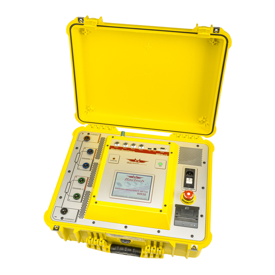
Page 20: Wr14
1 x Host 1 x Device Temp 1 9: Temperature receptacle 1...2 5: Thermal Temp 2 Printer 8: Extern Extern 7: Earth 6: Display with Touch Panel Instruction Manual Winding Resistance Meter Page 20 of 85 Type WR50, WR14, Version 2.01... - Page 21 1: Charge Indicator This LED is blinking if the battery is charging, although if the WR14 is switched off. If the instrument is switched on and the battery is not charging, the LED is on. 2: Main Switch Press to switch the WR14 on / off.
- Page 22 Press to stop: The measurement will stop and immediately start to discharge the Transformer. Turn clockwise to release. The device will remain in a safe mode state. 14: Main Input Connect the power cable to the Main Input. Instruction Manual Winding Resistance Meter Page 22 of 85 Type WR50, WR14, Version 2.01...
-
Page 23: Operating Menu
6 Operating Menu 6.1 Menu Structure Start up screen: Example WR50 Instruction Manual Winding Resistance Meter Page 23 of 85 Type WR50, WR14, Version 2.01... -
Page 24: Main Menu
Demagnetizes the core of a test object. See chapter 6.2.5 Setup Goes directly to the Setup Menu. See chapter 6.2.6 Results Goes directly in the Results Menu. See chapter 6.3 Instruction Manual Winding Resistance Meter Page 24 of 85 Type WR50, WR14, Version 2.01... -
Page 25: Start
Instrument stops the measurement and begins the discharge process. DO NOT disconnect the measuring cables until the green light is on and the indication Safe appears. Instruction Manual Winding Resistance Meter Page 25 of 85 Type WR50, WR14, Version 2.01... -
Page 26: Demag
Demagnetizing procedure runs automatically. For a technical description of the demagnetizing feature: See Appendix: F Demagnetizing on Page 77. Instruction Manual Winding Resistance Meter Page 26 of 85 Type WR50, WR14, Version 2.01... -
Page 27: Setup
This screen allows the selection, modification and setting of the range for the Test Current. Temp. Corr. This screen activates the temperature correction feature. Colors This screen allows the modification and changes of the screen colors. Instruction Manual Winding Resistance Meter Page 27 of 85 Type WR50, WR14, Version 2.01... -
Page 28: General
Touch the text box (i.e. R1). Press To store the settings Press @ For special characters Press “Close” To finish input The third channel is only available in the WR50-13 Instruction Manual Winding Resistance Meter Page 28 of 85 Type WR50, WR14, Version 2.01... -
Page 29: Mux A / Mux B
See chapter 6.2.7.2 Alternative Caption. With “Set Labels” you can change the standard or you can set your own names by touching the text box. Instruction Manual Winding Resistance Meter Page 29 of 85 Type WR50, WR14, Version 2.01... -
Page 30: Length Correction
Ohm/Length. The test results are then corrected to the selected display method. The length of the test object is pre-defined by the customer. Enter the length of the test specimen. Instruction Manual Winding Resistance Meter Page 30 of 85 Type WR50, WR14, Version 2.01... -
Page 31: License
Raytech GmbH. Extend the license To modify or extend the license, enter a new license code. The license code is generated by Raytech GmbH. Instruction Manual Winding Resistance Meter Page 31 of 85 Type WR50, WR14, Version 2.01... -
Page 32: Firmware Update
6.2.7.7 Language The selection of languages for the operating menu can be made. To activate the desired language, restart the instrument after the selection is made. Instruction Manual Winding Resistance Meter Page 32 of 85 Type WR50, WR14, Version 2.01... -
Page 33: Clock Settings
The date format is: Month/Day/Year Time: Select hour/minute/second by highlighting the numbers in the clock. By pressing the arrows the time will increase or decrease. Instruction Manual Winding Resistance Meter Page 33 of 85 Type WR50, WR14, Version 2.01... -
Page 34: About
Select the desired printer to print results. Printers not listed are not supported. For more Information see chapter D USB Printer Info on page 73. Instruction Manual Winding Resistance Meter Page 34 of 85 Type WR50, WR14, Version 2.01... -
Page 35: Service Mode
If you don’t have, press anywhere on the display to accept the new parameters. Instruction Manual Winding Resistance Meter Page 35 of 85 Type WR50, WR14, Version 2.01... -
Page 36: Wr14 Ground Warning
6.2.7.11.2 WR14 Ground Warning Every time you switch the WR14 on, you get a Warning, that the Unit must be connected to Earth Ground for operator Safety. It’s possible to disable the Warning: After entering the code “0200”# in the Service Mode, you... -
Page 37: Mode
If the selected conditions are almost met, a yellow light in the main screen will illuminate. Instruction Manual Winding Resistance Meter Page 37 of 85 Type WR50, WR14, Version 2.01... -
Page 38: Interval
No results stored. If the selected conditions are almost met, a yellow light in the main screen will illuminate and indicate this condition. No results stored. Instruction Manual Winding Resistance Meter Page 38 of 85 Type WR50, WR14, Version 2.01... - Page 39 If this feature is selected, the instrument additionally prints the results to a connected printer when a measurement will be stored. AutoSave USB: The results will be additionally stored on a USB-Key during a measurement. Not available in WR14 Instruction Manual Winding Resistance Meter Page 39 of 85 Type WR50, WR14, Version 2.01...
-
Page 40: Range
Current level. Press OK when finished. The maximum current of the WR50 is 50A The maximum current of the WR14 is 15A Instruction Manual Winding Resistance Meter Page 40 of 85 Type WR50, WR14, Version 2.01... -
Page 41: Temp. Corr
In the example below, the measurement object is Copper and will be corrected to 25 degrees Celsius based on the temperature input of temperature channel 1. If you do not have a Raytech temperature probe, activate the “Ext” box and fill in the temperature of the test object you measure with an external temperature meter. - Page 42 In this example it is corrected to 25 °C using Tk of Copper and referring to Temperature probe 1. Instruction Manual Winding Resistance Meter Page 42 of 85 Type WR50, WR14, Version 2.01...
- Page 43 If the display shows a crossed Red T, the result is not corrected because a temperature probe is missing or not recognized by the system. Instruction Manual Winding Resistance Meter Page 43 of 85 Type WR50, WR14, Version 2.01...
-
Page 44: Colors
For example bright sun light. Choose a color by selecting a predefined color available. Choose a color by manually adjusting the color select bar. Instruction Manual Winding Resistance Meter Page 44 of 85 Type WR50, WR14, Version 2.01... -
Page 45: Results
Deletes the selected measurement. Delete All: Deletes all stored measurements. After selecting delete, a warning window will appear to confirm this choice. Deleting selected files is permanent. Instruction Manual Winding Resistance Meter Page 45 of 85 Type WR50, WR14, Version 2.01... -
Page 46: Open
Data/Delete in the menu. If you exit the Details after selecting delete, a warning window will appear to confirm this choice. Deletion is permanent. Instruction Manual Winding Resistance Meter Page 46 of 85 Type WR50, WR14, Version 2.01... -
Page 47: Export
Only activated with the option HRT (Heat Run Test) For an explanation see chapter 7.2 The AHRT01 can also be ordered later from Raytech USA (Part Number 2042N-11001) Instruction Manual Winding Resistance Meter Page 47 of 85 Type WR50, WR14, Version 2.01... -
Page 48: Battery Operation Wr14
A connector-symbol is inside the Battery. Battery charging The filling inside the Battery moves from the left to the right. The LED on the main switch is blinking if the battery is charging, although if the WR14 is switched off. Charging condition With the help of the filling inside the Battery you can see the charging condition: If the Battery is filled totally green, the Battery is 100% charged. -
Page 49: Low Battery
Very low Battery If the charging of the Battery is very low, the WR14 displays a second Warning and shoots down the instruments if no mains supply will connect. Instruction Manual Winding Resistance Meter Page 49 of 85 Type WR50, WR14, Version 2.01... -
Page 50: Options
7 Options 7.1 Temperature Measurement The Raytech WR-Instruments are very accurate and precise test systems. To take full advantage of this high accuracy, recording the temperature of the device under test is highly recommended. This is due to the characteristics of the increase in resistance of a metallic object as its temperature increases. -
Page 51: Heat Run Test Software
Select the time in seconds between measuring points and the number of data points. Temperature correction must be deactivated for Heat run testing. Disable although the Quality Assistant. Instruction Manual Winding Resistance Meter Page 51 of 85 Type WR50, WR14, Version 2.01... -
Page 52: Measurement With Interval Mode For Hrt
Measurement results should be obtained as quickly as possible. To start the measurement press “START”. The current is applied and the system charges the transformer Winding(s) to be measured. Instruction Manual Winding Resistance Meter Page 52 of 85 Type WR50, WR14, Version 2.01... - Page 53 After storing the last measurement the instrument turns off the output Current, stops the measurement, starts automatically to discharge the transformer till the test object is save. Instruction Manual Winding Resistance Meter Page 53 of 85 Type WR50, WR14, Version 2.01...
-
Page 54: Analysing The Hrt Results
The graph of the measured values is shown. With “Save” you can store the graph as a gif-file to the internal memory. Instruction Manual Winding Resistance Meter Page 54 of 85 Type WR50, WR14, Version 2.01... - Page 55 Exponential Approximation: R0: Winding resistance at time t = zero tau: Time constant R ∞: Winding resistance at time t = ∞ Cor: Correlation of the approximation Instruction Manual Winding Resistance Meter Page 55 of 85 Type WR50, WR14, Version 2.01...
-
Page 56: Showing The Graph In °C
Linear Approximation: T0: Temperature at time t = zero Slew rate dt/dt in °/ min Cor: Correlation of the approximation Instruction Manual Winding Resistance Meter Page 56 of 85 Type WR50, WR14, Version 2.01... - Page 57 T0: Temperature at time t = zero tau: Time constant R ∞: Temperature at time t = ∞ Cor: Correlation of the approximation The approximation and the values are shown as Temperature. Instruction Manual Winding Resistance Meter Page 57 of 85 Type WR50, WR14, Version 2.01...
-
Page 58: Cable Extension
The 2040N-05003 consists of the following cables: 2x 10m Extensions for 2x 10m Extensions for 2x 10m Extensions for the Current cables the Potential channel 1 the Potential channel 2 Instruction Manual Winding Resistance Meter Page 58 of 85 Type WR50, WR14, Version 2.01... -
Page 59: 2041N-05003
Current cables 2x 10m Extensions for 2x 10m Extensions for 2x 10m Extensions for the Potential channel 1 the Potential channel 2 the Potential channel 3 Instruction Manual Winding Resistance Meter Page 59 of 85 Type WR50, WR14, Version 2.01... -
Page 60: 2043N-05000
7.3.3 2043N-05000 The WR14 is available with an optional 10m cable set instead of the 5m cable set. System part number 2043N-05000 is the WR14, including 2043N-05001. The 2043N-05001 consists of the following cables: 2x 10m Current cables 2x 10m Potential... -
Page 61: Technical Specification
- Data Storage of up to 10000 measurements - Fastest discharge time in the market - 5 Year standard warranty Specifications are subject to change without notice. Instruction Manual Winding Resistance Meter Page 61 of 85 Type WR50, WR14, Version 2.01... -
Page 62: Wr14
- Data Storage of up to 10000 measurements - Fastest discharge time in the market - 5 Year standard warranty - Battery operated Specifications are subject to change without notice. Instruction Manual Winding Resistance Meter Page 62 of 85 Type WR50, WR14, Version 2.01... -
Page 63: Interfaces
(fixed, not changeable) Port RS232 Baudrate 38400 Baud Databit 8 Bit Stopbits 1 Bit Parity 9.1.2 USB 9.1.3 USB USB-Master USB Slave Standard 1.1 Standard 1.1 Instruction Manual Winding Resistance Meter Page 63 of 85 Type WR50, WR14, Version 2.01... -
Page 64: Extern
The contact is open when the system is Safe. The contact is closed when the system is Unsafe. Pins 1 and 2 on the Extern connector: These pins are for Raytech Service use. Do not connect anything to these pins! -
Page 65: Example For Connecting An External Warning Device
Dangerous condition. The function for this pins are the same as with the standard type, see chapter “9.1.4.1 Standard type” on page 64. Pins 1 and 2 on the Extern connector: These pins are for Raytech Service use. Do not connect anything to these pins! - Page 66 It has a bridge between Pin 5 and Pin 6 Extended Safety Circuit type with 6 pins: Connector in the instrument Extern Lemo: ERA.1E.306.CLL Lemo: FFA.1E.306.CLAC60 RAN: 40802 RAN: 40803 Instruction Manual Winding Resistance Meter Page 66 of 85 Type WR50, WR14, Version 2.01...
-
Page 67: Appendix
APPENDIX WR14 Winding Resistance Meter 15A WR50-12 / 13 Winding Resistance Meter 50A Raytech USA, Inc., 118 South 2nd Street, Perkasie, PA 18944... - Page 68 D USB Printer Info......................73 E Measuring high- and low-voltage-side in series ..............74 F Demagnetizing .......................77 G Multiplexer ........................79 H Warranty Conditions .......................80 Error Messages ......................82 Troubleshooting......................84 K Contacts .........................85 Instruction Manual Winding Resistance Meter Page 68 of 85 Type WR50, WR14, Version 2.01...
-
Page 69: A Raytech Toolbox
A Raytech Toolbox The Raytech Toolbox is another option for Data Exchange between the measuring instrument and an external computer. The Raytech Toolbox can be downloaded free of charge. Contact Raytech USA. Instruction Manual Winding Resistance Meter Page 69 of 85... -
Page 70: B Software Development Kit Sdk
Raytech USB Driver for Windows provides the OS with full device functionality, appearing to OS as Raytech USB device. This software can also be used without native Raytech USB drivers to control the device over the standard RS 232 Serial port. -
Page 71: C Command Syntax
WR14, WR50, WR100 A description of all commands (90014 Command Set WRxx) is stored on the delivered USB- Key. The newest version is available from Raytech USA. Instruction Manual Winding Resistance Meter Page 71 of 85... -
Page 72: Usb Interface
C.B USB Interface Related Firmware 2.7.0.0 and later. A description of all commands is available from Raytech USA. There you find although the USB-driver and an installation guide. The USB-driver installation is not necessary in order to use the RS 232 serial port for communication with the device. -
Page 73: D Usb Printer Info
HP-Laserjet P1505N HP-Laserjet P2055DN HP Color Laserjet CP2025N PocketJet 200 PocketJet II The information in this document is subject to change without notice. Instruction Manual Winding Resistance Meter Page 73 of 85 Type WR50, WR14, Version 2.01... -
Page 74: E Measuring High- And Low-Voltage-Side In Series
H1:X2 H2:X3 H3:X3 H1:X1 H2:X2 H3:X3 H1:X1 H2:X2 H3:X2 H1:X3 H2:X1 H3:X2 H1:X3 H2:X1 H3:X1 H1:X2 H2:X3 H3:X3 H1:X1 H2:X2 H3:X0 H1:X0 H2:X0 H3:X0 H1:X0 H2:X0 Instruction Manual Winding Resistance Meter Page 74 of 85 Type WR50, WR14, Version 2.01... - Page 75 H1:X2 H2:X3 H0:X1 H0:X2 H0:X3 H0:X3 H0:X1 H0:X2 H0:X2 H0:X3 H0:X1 H0:X1 H0:X2 H0:X3 H0:X1 H0:X2 H0:X3 H0:X0 H0:X0 H0:X0 H3:X1 H1:X2 H2:X3 H3:X3 H1:X1 H2:X2 Instruction Manual Winding Resistance Meter Page 75 of 85 Type WR50, WR14, Version 2.01...
- Page 76 The table is in ANSI standard. You can change it e.g. to the ICE standard by substitute H1 to 1U H2 to 1V H3 to 1W… Instruction Manual Winding Resistance Meter Page 76 of 85 Type WR50, WR14, Version 2.01...
-
Page 77: F Demagnetizing
8 times the nominal current flow. This hazardous situation may cause tripping of over-current relays, damage to the insulation medium and deformation of the transformer windings. Instruction Manual Winding Resistance Meter Page 77 of 85 Type WR50, WR14, Version 2.01... - Page 78 Equipment required to fully demagnetize a transformer in this manner is large and expensive. A better solution is the new Raytech Winding Resistance Meter, WR-Series. These easy to use systems are recognized throughout the World for Precision Winding Resistance measurements.
-
Page 79: G Multiplexer
Description Raytech Multiplexer is designed to drastically reduce cabling time and increase test performance. It is made to be used with Raytech Winding Resistance and Turns Ratio Meters. Any Multiplexer configuration can be easily controlled by a Winding Resistance Meters touch panel or by remote. -
Page 80: H Warranty Conditions
H Warranty Conditions RAYTECH USA, Inc. warrants to the original purchaser that it’s products shall be free from defects in material and workmanship under normal use and service for a period of 60 months from the original date of shipment. An additional extended warranty period is provided, at... - Page 81 Exclusive remedies provided herein are the customer’s sole and exclusive remedies. RAYTECH USA, Inc. shall not be liable for any damages resulting from the use of this equipment whether direct, indirect, special, incidental, or consequential damages, or whether based on contract, tort, or any other legal theory.
-
Page 82: I Error Messages
I Error Messages The Raytech instruments are designed to be trouble free, so you may not see many error messages. The emergency switch is activated. In this condition it is not possible to start a measurement. Exit this message screen by touching “OK”... - Page 83 WR- instrument USB port. Plug the USB key in and try again. The following will appear. The data can then be exported. Instruction Manual Winding Resistance Meter Page 83 of 85 Type WR50, WR14, Version 2.01...
-
Page 84: J Troubleshooting
2. Poor test lead connection. 3. Poor supply power source. Check extension cords, plugs and cables carefully. 4. Test set attached to a “Live” load or high interference load. Instruction Manual Winding Resistance Meter Page 84 of 85 Type WR50, WR14, Version 2.01... -
Page 85: K Contacts
Can’t switch off the WR14 Disconnect the power cable and press the main switch for 5 seconds. NOTE The WR-instruments are designed to be trouble free. If problems or questions do arise please contact your nearest representative or our service support group in Pennsylvania.
Need help?
Do you have a question about the WR14 and is the answer not in the manual?
Questions and answers