Table of Contents
Advertisement
Advertisement
Table of Contents

Related Manuals for Neousys Technology Nuvo-5002E


Summary of Contents for Neousys Technology Nuvo-5002E
- Page 1 Neousys Technology Inc. Nuvo-5000 Series ® Intel -Gen Core™ i7/i5/i3 Fanless Controller Nuvo-5002E, Nuvo-5006E Nuvo-5002P, Nuvo-5006P Nuvo-5002LP, Nuvo-5006LP Nuvo-5006E-PoE, Nuvo-5006P-PoE, Nuvo-5006LP-PoE User’s Manual Rev. A1 Published May 18 , 2015...
- Page 2 Revision History Date Change List Version 2015/5/18 First formal release...
-
Page 3: Table Of Contents
Copyright and Trademarks......................7 Chapter 1 Introduction..........................8 1.1 Overview............................. 8 1.2 Product Specification....................... 9 1.2.1 Specification of Nuvo-5002E/P and Nuvo-5006E/P..........9 1.2.2 Specification of Nuvo-5002LP and Nuvo-5006LP..........11 1.2.3 Specification of Nuvo-5006E-PoE/5006P-PoE/5006LP-PoE......13 1.3 List of Supported CPU......................15 Chapter 2 Getting to Know your Nuvo-5000.................. 16 2.1 Unpacking your Nuvo-5000 Controller................ - Page 4 2.5.2 MezIO Module for Nuvo-5000 Series..............39 2.6 Expansion Cassette....................... 41 2.6.1 Cassette of Nuvo-5006E/5002E................42 2.6.2 Cassette of Nuvo-5006P/5002P................43 2.6.3 Neousys Cassette Module..................44 2.6.4 Fan Option of Cassette..................... 45 2.7 Mechanical Dimension......................46 2.7.1 Top View of Nuvo-5000E/5000P Series............... 46 2.7.2 Front View of Nuvo-5000E/5000P Series.............47 2.7.3 Side View of Nuvo-5000E/5000P Series..............
- Page 5 3.10.2 Power on Nuvo-5000 Using an External Non-latched Switch.......82 3.10.3 Power on Nuvo-5000 Using Wake-on-LAN Function........83 Chapter 4 BIOS and Driver.........................86 4.1 BIOS Settings.......................... 86 4.1.1 COM Port Configuration....................87 4.1.2 SATA Port Configuration..................88 4.1.3 Hot Plug for SATA Port #1..................89 4.1.4 Enable TPM Feature....................90 4.1.5 Configure CPU SKU Power..................
-
Page 6: Declaimer
This manual is intended to be used as a practical and informative guide only and is subject to change without prior notice. It does not represent commitment from Neousys Technology Inc. Neousys shall not be liable for direct, indirect, special, incidental, or consequential damages arising out of the use of the product or documentation, nor for any infringements upon the rights of third parties, which may result from such use. -
Page 7: Chapter 1 Introduction
Chapter 1 Introduction 1.1 Overview Integrating cutting-edge technologies, Neousys creates the next-generation fanless controller, Nuvo-5000 series, with ruggedness, performance and versatility. It supports socket-type, 6th-Gen Core™ processors for flexible CPU selection from Pentium® to Core™ i7 according to performance consideration, and remains -25°C to 70°C true wide-temperature operating. -
Page 8: Product Specification
2x Gen3, 6 Gb/s SATA ports for 2.5” HDD/SSD installation, supporting RAID 0/1 mSATA 1x full-size mSATA port (mux with mini-PCIe) Expansion Bus 1x PCI slot in Cassette (Nuvo-5002P/5006P) PCI/PCI Express 1x PCIe x16 slot @ Gen3, 8-lanes signals in Cassette (Nuvo-5002E/5006E) - Page 9 Maximal power consumption is measured with 100% CPU and 3D loading applied using Passmark® BurnInTest™ v8.0. No Ethernet connection and external PoE devices are connected. or detail testing criteria, please contact Neousys Technology. For i7-6700 running at 65W mode, the high operating temperature shall be limited to 50°C and thermal throttling may occur when sustained full-loading applied.
-
Page 10: Specification Of Nuvo-5002Lp And Nuvo-5006Lp
1.2.2 Specification of Nuvo-5002LP and Nuvo-5006LP System Core Supports the following CPU Intel® Core™ i7-6700 (8M Cache,3.4/4.0 GHz, 65W TDP)* Intel® Core™ i5-6500 (6M Cache, 3.2/3.6 GHz, 65W TDP)* Intel® Core™ i3-6100 (3M Cache, 3.7 GHz, 51W TDP)* Intel® Pentium® G4400 (3M Cache, 3.3 GHz, 54W TDP)* Processor Intel®... - Page 11 Maximal power consumption is measured with 100% CPU and 3D loading applied using Passmark® BurnInTest™ v8.0. No Ethernet connection and external PoE devices are connected. or detail testing criteria, please contact Neousys Technology. For i7-6700 running at 65W mode, the high operating temperature shall be limited to 50°C and thermal throttling may occur when sustained full-loading applied.
-
Page 12: Specification Of Nuvo-5006E-Poe/5006P-Poe/5006Lp-Poe
1.2.3 Specification of Nuvo-5006E-PoE/5006P-PoE/5006LP-PoE System Core Support the following CPU Intel® Core™ i7-6700 (8M Cache,3.4/4.0 GHz, 65W TDP)* Intel® Core™ i5-6500 (6M Cache, 3.2/3.6 GHz, 65W TDP)* Intel® Core™ i3-6100 (3M Cache, 3.7 GHz, 51W TDP)* Intel® Pentium® G4400 (3M Cache, 3.3 GHz, 54W TDP)* Processor Intel®... - Page 13 Maximal power consumption is measured with 100% CPU and 3D loading applied using Passmark® BurnInTest™ v8.0. No Ethernet connection and external PoE devices are connected. or detail testing criteria, please contact Neousys Technology. For i7-6700 running at 65W mode, the high operating temperature shall be limited to 50°C and thermal throttling may occur when sustained full-loading applied.
-
Page 14: List Of Supported Cpu
1.3 List of Supported CPU ® Nuvo-5000 series supports Intel -Gen Core i7/i5/i3, Pentium and Celeron processor via the LGA1151 CPU socket. You can choose the following processors according to your consideration of cost and performance. l Intel® Core™ i7-6700TE Processor (8M Cache, up to 3.40 GHz, 35W TDP)* l Intel®... -
Page 15: Chapter 2 Getting To Know Your Nuvo-5000
When you receive the package of Nuvo-5000 series, please check immediately if the package contains all the items listed in the following table. If any item is missing or damaged, please contact your local dealer or Neousys Technology Inc. for further assistance. -
Page 16: Front Panel I/O Functions
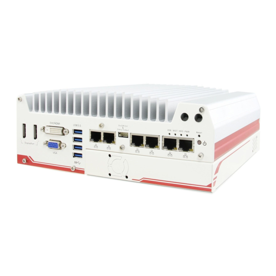
2.2 Front Panel I/O Functions On Nuvo-5000 series, plenty of I/O functions are provided on front panel and back panel so you can easily access them. All models of Nuvo-5000 series share the same I/O allocation and the only difference is the number of Ethernet port. We use Nuvo-5006 as an example for illustrating I/O functions. -
Page 17: Reset Button
2.2.2 Reset Button The reset button is used to manually reset the system in case of any abnormal condition. To avoid unexpected operation, the reset button is hidden behind the front panel. You need to use a pin-like object to push the reset button. 2.2.3 LED Indicators There are four LED indicators on the front panel: PWR, HDD, WDT, and IGN. -
Page 18: Gigabit Ethernet Port
2.2.4 Gigabit Ethernet Port Nuvo-5000 series offers 6 GbE ports (Nuvo-5006E/5006P/5006LP) or 2 GbE ports ® (Nuvo-5002E/5002P/5002LP). The GbE port marked in blue is designed with Intel I219-LM ® and ports marked in red are implemented with Intel I210-IT Gigabit Ethernet controllers. -
Page 19: Remote On/Off Control And Status Led Output
42.2.5 Remote On/Off Control and Status LED Output For an application which places Nuvo-5000 controller inside a cabinet, it’s useful to control the on/off of the system via an external switch, as well as check how the system’s running via some external LED indicators. Nuvo-5000 series provides a 2x5, 2.0mm pitch wafer connector on the front panel for this purpose. -
Page 20: Usb 3.0 Connectors
Pin#3 to pin#10 are used to output the system status including power, HDD, and watchdog timer status. Pin#1 and pin#2 are used to turn on or turn off the system remotely by connecting an external switch. Users should connect a non-latched switch to Ctrl+/Ctrl- as it acts exactly the same as the power button on the front panel. -
Page 21: Dvi/Hdmi Connectors
2.2.7 DVI/HDMI Connectors Nuvo-5000 series has multiple display outputs on its front panel for connecting different displays according to your system configuration. DVI/HDMI transmits graphics data in digital format and therefore can deliver better image quality at high resolution. The DVI/HDMI connector on the front panel can either output DVI signals or HDMI signal depending on the display device connected. -
Page 22: Vga Connector
2.2.8 VGA Connector Nuvo-5000 series has multiple display outputs on its front panel for connecting different displays according to your system configuration. VGA connector is the most popular way for connecting a display. The VGA output on Nuvo-5000 series supports up to 1920 x 1200 resolution. -
Page 23: Displayport
2.2.9 DisplayPort Nuvo-5000 series has multiple display outputs on its front panel for connecting different displays according to your system configuration. Two DisplayPort (DP) connectors are available for high-resolution graphics outputs. They can deliver 4096 x 2304 resolution when single DP port is used or 2880 x 1800 resolution when both DP ports are simultaneously used. -
Page 24: Back Panel I/O Functions
2.3 Back Panel I/O Functions To fit general application requirements, Nuvo-5000 series offers more I/O functions on its back panel. In this section, we’ll illustrate each I/O function on the back panel. 2.3.1 3-Pin Terminal Block for DC and IGN Input Nuvo-5000 series allows a wide range of DC power input from 8 to 35V via a 3-pin pluggable terminal block, which is fit for field usage where DC power is usually provided. -
Page 25: Com Ports (Com1 / Com2 / Com3)
2.3.2 COM Ports (COM1 / COM2 / COM3) Nuvo-5000 series provides three COM ports for communicating with external devices. COM1, COM2 and COM3 are located on the back panel via 9-pin D-Sub male connectors. hey are implemented using industrial-grade ITE8786 Super IO chip (-40 to 85°C) and provide up to 115200 bps baud rate. -
Page 26: Usb2.0 Connectors
2.3.3 USB2.0 Connectors In addition to USB 3.0, Nuvo-5000 Series provides four USB 2.0 ports on the back panel. They are implemented by native xHCI (eXtensible Host Controller Interface) controller in Q170 chipset and are compatible with USB 2.0, USB 1.1 and USB 1.0 devices. Legacy USB support is also provided so you can use USB keyboard/mouse in DOS environment. -
Page 27: Mezio I/O Connector
2.3.5 MezIO I/O Connector Nuvo-5000 series is designed to incorporate Neousys’ MezIO interface. You can install a MezIO module to expand application-oriented I/O function. To support MezIO connectivity, Nuvo-5000 series reserves the cutting hole for a SCSI-II 68-pin connector on its back panel. -
Page 28: Internal I/O Functions
2.4 Internal I/O Functions In addition to I/O connectors on the front/back panel, Nuvo-5000 series provides other features via its on-board connectors, such as SATA ports, mini-PCIe sockets, internal USB ports and MezIO interface. In this section, we’ll illustrate these internal I/O functions. 2.4.1 DDR4 SODIMM Sockets Nuvo-5000 series provides two 260-pin, SODIMM sockets for installing DDR4 memory modules. -
Page 29: Msata / Mini-Pcie #1 Dual-Mode Socket
2.4.2 mSATA / mini-PCIe #1 Dual-Mode Socket Nuvo-5000 series provides two mini-PCIe sockets compliant with mini-PCIe specification rev. 1.2. The first socket supports mini-PCIe and mSATA dual mode operation. You can install either a mSATA SSD or mini-PCIe module into this socket. The system automatically detects and configures it to run PCIe or SATA signals according to installed module. - Page 30 The following table describes the pin definition of mSATA/mini-PCIe #1 dual-mode socket. Pin # Signal (mPCIe) Signal (mSATA) Pin # Signal (mPCIe) Signal (mSATA) WAKE# +3.3Vaux +3.3Vaux COEX1 COEX2 +1.5V +1.5V CLKREQ# UIM_PWR UIM_DATA REFCLK- UIM_CLK REFCLK+ UIM_RESET UIM_VPP Mechanical Key Reserved* (UIM_C8) Reserved*...
-
Page 31: Mini-Pcie #2 Socket
2.4.3 Mini-PCIe #2 Socket Nuvo-5000 series provides two mini-PCIe sockets compliant with mini-PCIe specification rev. 1.2. The second mini-PCie socket works with the panel-accessible SIM slot. There are plenty of off-the-shelf mini-PCIe modules with versatile capabilities. By installing a mini-PCIe module, your system can have expanded features such as WIFI, GPS, CAN bus, analog frame grabber and etc. - Page 32 The following table describes the pin definition of mini-PCIe #2 socket. Pin # Signal Pin # Signal WAKE# +3.3Vaux COEX1 COEX2 +1.5V CLKREQ# UIM_PWR UIM_DATA REFCLK- UIM_CLK REFCLK+ UIM_RESET UIM_VPP Mechanical Key Reserved* (UIM_C8) Reserved* (UIM_C4) W_DISABLE# PERST# PERn0 +3.3Vaux PERp0 +1.5V SMB_CLK...
-
Page 33: Internal Sata Port #1
Each SATA port is composed of a 7-pin SATA connector and a 4-pin power connector. In Nuvo-5002E/P and 5006E/P, SATA port #1 is used in conjunction with the HDD bracket to accommodate the first 2.5” HDD/SSD. A dedicated cable is shipped with the system to provide standard 22-pin SATA connector. -
Page 34: Internal Sata Port #2
2.4.5 Internal SATA Port #2 Nuvo-5000 series provides two SATA ports which support Gen3, 6 Gb/s SATA signals. Each SATA port is composed of a 7-pin SATA connector and a 4-pin power connector. For all models of Nuvo-5000 series, SATA port #2 is used in conjunction with the HDD bracket to accommodate the second 2.5”... -
Page 35: Internal Usb Port
2.4.6 Internal USB Port Nuvo-5000 series provides one additional USB port internally on the PCBA. It supports standard USB 2.0 signals. You can utilize this USB port to connect a USB protection dongle inside the chassis of Nuvo-5000 controller. -
Page 36: Mezio Tm Interface
2.5 MezIO Interface MezIO is an innovative interface designed for integrating application-oriented I/O functions into an embedded system. It offers computer signals, power rails and control signals via a high-speed connector. MezIO is also mechanically reliable benefited from its 3-point mounted mezzanine structure. A MezIO module can leverage these signals to implement comprehensive I/O functions. - Page 37 Function Function Signal Signal Description Description Reserved Reserved PCIE_TXP_0 PCIe data pair Reserved Reserved PCIE_TXN_0 PCIe data pair Reserved Ground Reserved Reserved PCIe data pair Reserved PCIE_RXP_0 System S4 signal PCIe data pair SLP_S4# PCIE_RXN_0 Ground CLK100_P_0 PCIe clock pair Reserved Reserved CLK100_N_0...
-
Page 38: Mezio Module For Nuvo-5000 Series
2.5.2 MezIO Module for Nuvo-5000 Series Neousys offers standard MezIO modules to expand I/O functions for Nuvo-5000 series. Currently you can have more RS-232/422/485 ports, isolated digital I/O or ignition power control by installing the following module into your Nuvo-5000 controller. Neousys will continuously develop MezIO modules with versatile features for Nuvo-5000 series and other embedded products. - Page 39 16-CH isolated DI and 16-CH isolated MezIO-D230-50 DO MezIO module 16-mode ignition power control MezIO MezIO-V20 module (Nuvo-5000LP only)
-
Page 40: Expansion Cassette
2.6.4 for the fan option. The operating temperature of the whole system when cards installed is affected by the power consumption and operating temperature of add-on cards. Please consult your add-on card supplier or Neousys Technology for further information. -
Page 41: Cassette Of Nuvo-5006E/5002E
2.6.1 Cassette of Nuvo-5006E/5002E The expansion Cassette of Nuvo-5006E/5002E contains a backplane with a x16 PCI Express connector. It runs 8-lanes, Gen3 PCIe signals to provide a maximal 16 GB/s bandwidth. Nuvo-5006E/5002E supports 5A@12V rated current (60 watts) for a PCI Express add-on card with high power consumption. -
Page 42: Cassette Of Nuvo-5006P/5002P
2.6.2 Cassette of Nuvo-5006P/5002P The expansion Cassette of Nuvo-5006P/5002P contains a backplane with a 32-bit/33MHz PCI connector. Nuvo-5006P/5002P supports 5A@12V rated current (60 watts). You can get the 12VDC from the on-board power connectors if necessary. Connector Function Description 33MHz/32-bit PCI 33MHz/32-bit PCI bus via PLX8112 PCIe-to-PCI bridge 3-pin, 2.54mm pitch power connector for supplying 12VDC to the optional fan. -
Page 43: Neousys Cassette Module
2.6.3 Neousys Cassette Module Neousys offers several read-to-use Cassette modules with pre-installed functional card and cautiously-designed thermal solution. You can simply install a Cassette module to Nuvo-5000 series to obtain additional function without concerning any thermal issue. Model Description Product Photo Cassette module with 4-drives hardware CSM-R800 RAID 0/1/10, accommodating four 2.5”... -
Page 44: Fan Option Of Cassette
2.6.4 Fan Option of Cassette When an add-on card with high power consumption (e.g. PCIe graphics card) installed in Cassette, you need to consider the thermal dissipation. Neousys offers a fan option, as a general solution for versatile add-on cards, to create active air flow and maintain proper temperature inside Cassette. -
Page 45: Mechanical Dimension
2.7 Mechanical Dimension 2.7.1 Top View of Nuvo-5000E/5000P Series... -
Page 46: Front View Of Nuvo-5000E/5000P Series
2.7.2 Front View of Nuvo-5000E/5000P Series 2.7.3 Side View of Nuvo-5000E/5000P Series... -
Page 47: Bottom View Of Nuvo-5000E/5000P Series
2.7.4 Bottom View of Nuvo-5000E/5000P Series... -
Page 48: Top View Of Nuvo-5000Lp Series
2.7.5 Top View of Nuvo-5000LP Series 2.7.6 Front View of Nuvo-5000LP Series... -
Page 49: Side View Of Nuvo-5000Lp Series
2.7.7 Side View of Nuvo-5000LP Series 2.7.8 Bottom View of Nuvo-5000LP Series... -
Page 50: Chapter 3 Getting Start
Chapter 3 Getting Start In this chapter, we’ll illustrate how to disassemble your Nuvo-5000 controller and install all necessary components such as CPU, memory and hard drive. Please follow the correct procedures to prevent any damage on your Nuvo-5000 controller. Disassemble your Nuvo-5000 Controller In prior to install components such as CPU, memeory and HDD to Nuvo-5000 series, you need to disassemble Nuvo-5000 controller and expose the PCBA. - Page 51 Remove the bottom cover of Nuvo-5000E/P controller. You can see the PCBA exposed.
-
Page 52: Disassemble Nuvo-5000Lp Series
3.1.2 Disassemble Nuvo-5000LP Series Put the Nuvo-5000LP controller upside down on a flat surface. Unscrew six hex bolts on the front panel and another six hex bolts on the back panel. And remove both front panel and back panel. (another 6 hex bolts on the opposite side) Remove the bottom cover of Nuvo-5000LP controller and the SATA cable attached to the hot-swappable HDD tray. -
Page 53: Install And Replace Lga1151 Cpu
3.2 Install and Replace LGA1151 CPU Nuvo-5000 series supports 6 -Gen, LGA1151 socket-type CPU. You can select the CPU according to your consideration of performance, cost and ambient condition. This section describes how to install or replace the CPU on your Nuvo-5000 controller. Caution Please carefully handle the exposed LGA socket on PCBA. -
Page 54: Install A Cpu On Nuvo-5000 Rev. A1
3.2.2 Install a CPU on Nuvo-5000 Rev. A1 For a Nuvo-5000 Rev. A1 barebone (without CPU installed), please follow steps described below to install a CPU on it. Remove the PCBA from the heat-sink by loosing four M3 P-head screws(red circles). Place the PCBA on a flat surface. - Page 55 Make sure that you line up the two guiding notches on the LGA1151 socket with the notches along the edges of the CPU. Place the CPU into the socket and by holding it firmly by the sides and lowering it into the socket. Get the CPU retaining bracket from the accessory box.
- Page 56 Remove all protective films of thermal pads of the heat-sink. Put the PCBA back to heat-sink. Make sure all the screw holes on PCBA are aligned with mounting posts of the heat-sink.
- Page 57 Get five M3 spring screws from the accessory box. Fix them according to the order indicated on the photo (red circles). And tighten four M3 P-head screws (yellow circles) to fix the PCBA to the heat-sink.
-
Page 58: Replace The Cpu On Nuvo-5000 Rev. A1
3.2.3 Replace the CPU on Nuvo-5000 Rev. A1 For a Nuvo-5000 Rev. A1 with CPU installed, please follow steps described below to replace the CPU on it. Caution Please make sure the PCBA/heat-sink assembly is cooled down to room temperature before you proceed with the replacement/installation procedures. - Page 59 Gently lift the PCBA. Once you feel significant adhesion between PCBA and heat-sink, DO NOT apply more force for lifting it. In this case, please repeat step 2 to separate the PCBA from the heat-sink. Place the PCBA on a flat surface. The CPU is held by a bracket on the PCBA. Unscrew two M3 P-head screws to remove the CPU retaining bracket.
- Page 60 Check the condition of thermal pads on the heat-sink, especially the thermal pad for CPU. If it’s broken, please replace it with a new one. Follow steps described in step 3 to step 7 in section 3.2.2 to install a new CPU to your Nuvo-5000 controller.
-
Page 61: Install A Cpu On Nuvo-5000 Rev. A2
3.2.4 Install a CPU on Nuvo-5000 Rev. A2 For a Nuvo-5000 Rev. A2 barebone (without CPU installed), please follow steps described below to install a CPU on it. Remove the PCBA from the heat-sink by loosing four M3 P-head (red circles). Place the PCBA on a flat surface. - Page 62 Make sure that you line up the two guiding notches on the LGA1151 socket with the notches along the edges of the CPU. Place the CPU into the socket and by holding it firmly by the sides and lowering it into the socket. Get the CPU retaining bracket from the accessory box and place it on the top of CPU.
- Page 63 Remove all protective films of thermal pads of the heat-sink. Put the PCBA back to heat-sink. Make sure all the screw holes on PCBA are aligned with mounting posts of the heat-sink.
- Page 64 Get five M3 spring screws from the accessory box. Fix them according to the order indicated on the photo (red circles). And tighten four M3 P-head screws (yellow circles) to fix the PCBA to the heat-sink.
-
Page 65: Replace The Cpu On Nuvo-5000 Rev. A1
3.2.5 Replace the CPU on Nuvo-5000 Rev. A1 For a Nuvo-5000 Rev. A2 with CPU installed, please follow steps described below to replace the CPU on it. Caution Please make sure the PCBA/heat-sink assembly is cooled down to room temperature before you proceed with the installation/replacement procedures. - Page 66 Caution When the PCBA is detached and LGA1151 socket is exposed, please carefully handle the PCBA to avoid any damage on LGA socket. Insert a slotted screwdriver into the gap between the CPU retaining bracket and the heat-sink, and lever the CPU and bracket. Please DO NOT apply force to the CPU otherwise the CPU can be damaged.
-
Page 67: Install Ddr4 Sodimm Module
3.3 Install DDR4 SODIMM Module Nuvo-5000 series provides two 260-pin, SODIMM sockets for installing DDR4 memory modules. It supports maximal 32GB capacity by installing two 16 GB DDR4-2133 SODIMM modules. You can install/replace DDR4 SODIMM modules by following the steps described in this section. -
Page 68: Install Ddr4 Sodimm Module For Nuvo-5000Lp Series
3.3.2 Install DDR4 SODIMM Module for Nuvo-5000LP Series Follow the steps described in section 3.1.2 to disassemble the Nuvo-5000LP chassis. You can see the DDR4 SODIMM sockets on the PCBA exposed. Tile the SODIMM module and insert it to the SODIMM socket. As it’s firmly contacted with socket connectors, press it down until the clamps of the socket snap into the latching position of SODIMM module. -
Page 69: Install 2.5" Sata Hdd/Ssd
3.4 Install 2.5” SATA HDD/SSD Nuvo-5000 series has two SATA ports for connecting SATA HDD or SSD drives. On Nuvo-5000E/P series, SATA ports are used in conjunction with the HDD bracket on the trapdoor to accommodate two 2.5” HDD/SSD. On Nuvo-5000LP series, the first SATA port is connected to the panel-accessible, hot-swappable HDD tray and the second port is used in conjunction with the HDD bracket on the trapdoor. - Page 70 Place the HDD/SSD into the bracket and gently push it down to make it contact with the thermal pad. Use a Philips screwdriver to fix it with M3 flat-head screws from the accessory box. Please note that the HDD must be placed in the right direction as below.
-
Page 71: Install 2.5" Sata Hdd/Ssd To Hdd Tray (Nuvo-5000Lp Only)
3.4.1 Install 2.5” SATA HDD/SSD to HDD Tray (Nuvo-5000LP Only) Find the door of hot-swappable HDD tray on the front panel of Nuvo-5000LP controller. Pull the handle of the tray door to open the hot-swappable HDD tray. Insert the 2.5” HDD/SSD into the hot-swappable HDD tray. Please note the HDD must be placed in the right direction when you install it. -
Page 72: Install Mini-Pcie Module
3.5 Install Mini-PCIe Module Nuvo-5000 series provides two full-size mini-PCIe sockets with SIM card support. You can install off-the-shelf mini-PCIe modules to expand functions for Nuvo-5000 controller. In this section, we demonstrate how to install a mini-PCIe 3G module and its antenna to the Nuvo-5000 controller. - Page 73 Attach the IPEX-to-SMA cable to the 3G module. Fix the SMA connector of the IPEX-to-SMA cable to one of the four antenna apertures on either front panel of back panel. Recover the front panel, back panel and the bottom cover and attach a 3G antenna to the SMA connector.
-
Page 74: Install Mezio Tm Module
3.6 Install MezIO Module Nuvo-5000 series is designed with Neousys’ MezIO interface. You can install a MezIO module to expand application-oriented I/O function. In this section, we demonstrate the procedure of installing Neousys MezIO-C180 to add eight additional COM ports to your Nuvo-5000 controller. - Page 75 Remove the pre-cutting plate of MezIO I/O aperture on the back panel to expose the SCSI-II 68-pin connector of the MezIO-C180 module.
-
Page 76: Install Add-On Card In Cassette
3.7 Install Add-on Card in Cassette The expansion Cassette is used to accommodate a PCI Express or PCI add-on card. To install an add-on card into Cassette, please refer to the instructions described in this section. Remove Cassette from Nuvo-5000E/P controller by loosening four M4 screws. Pull the cover of Cassette toward arrow pointing direction to open it. - Page 77 Install a PCI/PCIe add-on card into the PCI/PCIe connector. Note that the tail of faceplate of the add-on card must be inserted into the mortise. Tighten the add-on card using a M3 screw. Recover Cassette and assemble it to Nuvo-5000 controller. Fix the Cassette with four M4 screws.
-
Page 78: Mount Your Nuvo-5000
3.8 Mount your Nuvo-5000 Nuvo-5000 series provides versatile ways of mounting. You can use wall-mounting brackets shipped with Nuvo-5000 series to mount it on the wall. Neousys also offers optional DIN rail mounting kit to mount it on a DIN rail. To mount your Nuvo-5000 controller, please refer to the instructions listed below. -
Page 79: Mount Your Nuvo-5000 On The Din Rail
For best efficiency of heat dissipation, please mount your Nuvo-5000 controller in a right direction. 3.8.2 Mount your Nuvo-5000 on the DIN Rail Neousys also provides the option of the DIN-rail mounting kit. The kit includes a bracket and a DIN-rail mounting clip. You should fix the clip to the bracket using four M4 flat-head screws first, and then fix the bracket assembly to the Nuvo-5000 controller with another four M4 screws. -
Page 80: Connect Dc Power To Your Nuvo-5000 Controller
Connect DC Power to your Nuvo-5000 Controller Nuvo-5000 series uses a 3-pin pluggable terminal block to accept 8~35V DC power input. It provides the reliable way for directly wiring the DC power. The pluggable terminal block is also used to accept ignition signal if MezIO-V20 ignition control module is installed. To connect DC power via the 3-pin pluggable terminal block, please follow the steps described below. -
Page 81: Power On Your Nuvo-5000 Controller
3.10 Power on your Nuvo-5000 Controller For better flexibility of operation, Nuvo-5000 series provides three alternatives to power on your Nuvo-5000 controller. You can turn on your Nuvo-5000 controller by pressing the power button, using an external non-latched switch, or by sending a special LAN packet. In this section, we illustrate these ways to power on your Nuvo-5000 controller. -
Page 82: Power On Nuvo-5000 Using Wake-On-Lan Function
Connect the wafer terminal to the wafer connector on the front panel of the Nuvo-5000 controller. Push the non-latched switch will turn on the system (the PWR LED indicator on the front panel is on at the same time). Push the non-latched switch when system is on will turn off the system. - Page 83 Click the Power Management tag, and check the following two options accordingly Wake on Magic Packet Nuvo-5000 series can wake from S5 state when receiving a magic packet. The magic packet is a broadcast frame containing anywhere within its payload 6 bytes of all 255 (FF FF FF FF FF FF in hexadecimal), followed by sixteen repetitions of the target computer's 48-bit MAC address.
- Page 84 For example, NIC’s 48-bit MAC Address is 78h D0h 04h 0Ah 0Bh 0Ch DESTINATION SOURCE MISC FF FF FF FF FF FF 78 D0 04 0A 0B 0C 78 D0 04 0A 0B 0C 78 D0 04 0A 0B 0C 78 D0 04 0A 0B 0C 78 D0 04 0A 0B 0C 78 D0 04 0A 0B 0C 78 D0 04 0A 0B 0C 78 D0 04 0A 0B 0C 78 D0 04 0A 0B 0C 78 D0 04 0A 0B 0C...
-
Page 85: Chapter 4 Bios And Driver
Chapter 4 BIOS and Driver 4.1 BIOS Settings Nuvo-5000 series is shipped with factory-default BIOS settings cautiously programmed for best performance and compatibility. In this section, we’ll illustrate some of BIOS settings you may need to modify. Please always make sure you understand the effect of change before you proceed with any modification. -
Page 86: Com Port Configuration
4.1.1 COM Port Configuration There are totally five COM ports implemented on Nuvo-5000 series. COM1, COM2 and COM3 are located on the back panel. COM4 and COM5 are internally used for MezIO interface. COM1 and COM3 of Nuvo-5000 series support RS-232 (full-duplex), RS-422 (full-duplex) and RS-485 (half-duplex) mode, while COM2 supports RS-232 mode only. -
Page 87: Sata Port Configuration
4.1.2 SATA Port Configuration The SATA controller of Nuvo-5000 series supports two operating modes: AHCI and RAID mode. AHCI mode, which exposes SATA's advanced capabilities such as hot swapping and native command queuing, is supported in most of modern operating systems. RAID mode provides a more reliable data storage (RAID 1/5/10) or a higher disk access throughput (RAID 0/5/10). -
Page 88: Hot Plug For Sata Port #1
4.1.3 Hot Plug for SATA Port #1 On Nuvo-5006LP and Nuvo-5002LP, SATA port #1 is connected to a panel-accessible HDD tray which supports hot-swap feature. You can simply eject the HDD and replace it with another one without turning off the system. By default, hot plug for SATA port # 1 is disabled in BIOS, you need to enable it in prior to support the hot-swap feature. -
Page 89: Enable Tpm Feature
4.1.4 Enable TPM Feature TPM, or Trusted Platform Module, is a hardware-based cryptoprocessor to secure hardware by integrating cryptographic keys into devices. Nuvo-5000 series is designed with on-board TPM 2.0 module. As TPM 2.0 requires 64-bit Windows 7/8/10 with UEFI boot mode, it is disable in BIOS by default. -
Page 90: Configure Cpu Sku Power
4.1.5 Configure CPU SKU Power Nuvo-5000 series supports a long list of 6 -gen Skylake LGA1151 CPU with up to 65W TDP. A unique feature, “SKU Power Config” is implemented in BIOS to allow users to specify user-defined SKU power limit for installed CPU according to deployment environment and power budget. -
Page 91: Wake-On-Lan Option
4.1.6 Wake-on-LAN Option Wake-on-LAN (WOL) is a mechanism which allows you to turn on your Nuvo-5000 controller via Ethernet connection. To utilize Wake-on-LAN function, you need to enable this option first in BIOS settings. Please refer to section 3.10.3 for instructions of using WOL function. -
Page 92: Power On After Power Failure Option
4.1.7 Power On after Power Failure Option The “Power On after Power Failure” option defines the behavior of Nuvo-5000 controller when DC power is supplied. Value Description S0 – Power On System is powered on when DC power is supplied. S5 –... -
Page 93: Configure Legacy/Uefi Boot Type
4.1.8 Configure Legacy/UEFI Boot Type Nuvo-5000 series supports both legacy and UEFI boot mode. UEFI, or Unified Extensible Firmware Interface, is a specification proposed by Intel to define a software interface between operating system and platform firmware. Most modern operating systems, such as Windows 7/8/10 and Linux, support both legacy and UEFI boot mode. -
Page 94: Position New Boot Device
4.1.9 Position New Boot Device When you plug a newly-installed boot device (e.g. USB flash disk), this option allow you determine whether to place the new boot device in the first place or the last place in the boot sequence. When Nuvo-5000 controller boots up, press F2 to enter BIOS setup utility. -
Page 95: Watchdog Timer For Booting
4.1.10 Watchdog Timer for Booting The BIOS of Nuvo-5000 series has a useful feature which allows users to use the watchdog timer to secure the booting process. You can specify the timeout value for watchdog timer. Once the watchdog timer expires, the BIOS issues a reset command to initiate another booting process. -
Page 97: Select A Boot Device
4.1.11 Select a Boot Device When you have multiple bootable devices connected to your Nuvo-5000 controller (e.g. HDD, mSATA, USB flash disk, USB DVD-drive), you may need to select one of them as the boot device. There are two ways to select the device. You can either, press F12 when system boots up to go to Boot Manager and then select one of the devices, or select the boot device in BIOS settings. -
Page 98: Configure Amt
4.2 Configure AMT Intel® AMT (Active Management Technology) is a hardware-based technology for remotely managing target PCs via Ethernet connection. Nuvo-5000 series supports AMT function via its Ethernet port implemented with Intel I219-LM. In prior to use AMT to remotely control Nuvo-5000 series, you need to configure AMT password and network settings. -
Page 99: Configure Raid Volume
4.3 Configure RAID Volume Nuvo-5000 series supports hardware RAID function for more reliable and efficient disk access. The built-in RAID supports RAID 0 (data stripping), RAID 1 (data mirroring), RAID 5 (data stripping + parity) and RAID 10 (data stripping + mirroring). You can configure RAID mode according to your application by following steps listed below. -
Page 100: Operating System Support
4.4 Operating System Support Nuvo-5000 series supports most modern operating systems developed for Intel® x86 architecture. The following list contains the operating systems which have been tested with Nuvo-5000 series in Neousys Technology Inc. Microsoft Window 7 32-bit* Microsoft Window 7 64-bit* Microsoft Window 8.1 64-bit... -
Page 101: Driver Installation
4.5 Driver Installation Neousys provides a very convenient utility in “Drivers & Utilities DVD” to allow the “One-Click” driver installation. This utility automatically detects your Windows operating system and installs all necessary drivers to your Nuvo-5000 controller with just one mouse click. -
Page 102: Install Drivers Manually
4.5.2 Install Drivers Manually You can also manually install each driver for Nuvo-5000 series. Please refer to the following information about installing drivers for different operating system. Windows 7 32-bit The recommended driver installation sequence is Chipset driver (x:\Driver_Pool\Chipset_10_Series\Win_ALL\SetupChipset.exe) Graphics driver (x:\Driver_Pool\Graphics_6th_i7\Win_7_32\Setup.exe) Audio driver (x:\Driver_Pool\Audio_ALC262\Win_ALL_32\Setup.exe) LAN driver (x:\Driver_Pool\GbE_I210_I350\Win_ALL_32\APPS\PROSETDX\Win32\DxSetup.exe) - Page 103 LAN driver (x:\Driver_Pool\GbE_I210_I350\Win_ALL_64\APPS\PROSETDX\Winx64\DxSetup.exe) ME driver (x:\Driver_Pool\ME_10_Series\Win_ALL_AMT\SetupME.exe)
-
Page 104: Install Driver For Wdt And Per-Port Poe On/Off Control
4.5.3 Install Driver for WDT and Per-port PoE On/Off Control Neousys provides a driver package which contain function APIs for WDT and per-port PoE power on/off control function. You should install the driver package (WDT_DIO_Setup.exe) in prior to use these functions. Please note that you must install WDT_DIO_Setup_v2.2.2 or later revision for Nuvo-5000 series. -
Page 105: Appendix A Install Windows 7 On Nuvo-5000
Appendix A Install Windows 7 on Nuvo-5000 Intel Skylake platform removes EHCI controller and supports USB 2.0 and USB 3.0 connectivity only through its xHCI controller. For Windows 8/8.1 and Windows10, no issue is anticipated due to native xHCI support in the OS. However, Windows 7 does not natively support xHCI thus manual installation of Intel’s xHCI driver is required to support both USB storage device and USB keyboard/mouse during the OS installation process. -
Page 106: Step 2 - Create Usb Flash Drive Installer From .Iso
Step 2 - Create USB flash drive installer from .ISO The next step is to create a bootable USB flash drive using the .iso file created in step 1. Here we use Microsoft Windows USB/DVD Download Tool to create the USB flash drive (https://www.microsoft.com/en-us/download/windows-usb-dvd-download-tool). -
Page 107: Step 3 - Create Working Folder On Your Local Drive
Step 3 - Create working folder on your local drive In this step, we need to create a working folder on your local drive and copy necessary files to it. Please following the steps below. 1. Create a temporary working folder on your local drive. Here we use D:\WIM as an example. -
Page 108: Step 4 - Execute Batch File To Patch .Wim Files
Step 4 - Execute batch file to patch .wim files To support xHCI for Windows 7 installation, both install.wim and boot.wim need to be patched to include xHCI driver files. Neousys offers Windows-based batch files (Win7_USB3_Patch_x86.bat for Windows 7 32-bit and Win7_USB3_Patch_x64.bat for Windows 7 64-bit) to simplify this process. -
Page 109: Step 5 - Install Windows 7 Using Usb Flash Drive Installer
The batch file will automatically patch both install.wim and boot.wim. It takes few minutes to finish the patch process. Once patch finished, please overwrite the \sources\install.wim and \sources\boot.wim in USB flash drive installer with the patched ones. Step 5 - Install Windows 7 using USB flash drive installer Now you can use the USB flash drive to install Windows 7 on your Nuvo-5000. -
Page 110: Appendix B Using Watchdog Timer
In this section, we’ll illustrate how to use the function library provided by Neousys to program the WDT functions. Currently, WDT driver library supports Windows 7/8.1/10 32-bit and 64-bit versions. For other OS support, please contact Neousys Technology for further information. - Page 111 To install WDT_DIO_Setup package, please follow steps described below. Execute WDT_DIO_Setup.2.2.20.exe. The following dialog appears. Click “Next >” and specify the directory of installing related files. The default directory is C:\Neousys\WDT_DIO.
- Page 112 Once the installation is finished, a dialog appears to prompt you to reboot the system. The WDT & DIO library will take effect after system rebooting. When you programming your WDT or DIO program, the related files are located in Header file: \Include Lib file:...
-
Page 113: Wdt Function Reference
WDT Function Reference InitWDT Syntax BOOL InitWDT(void); Description Initialize the WDT function. You should always invoke InitWDT() before set or start watchdog timer. Parameter None Return Value Returns TRUE if initialization successes, FALSE if initialization failed. Usage BOOL bRet = InitWDT() SetWDT Syntax BOOL SetWDT(WORD tick, BYTE unit);... - Page 114 StartWDT Syntax BOOL StartWDT(void); Description Start countdown of WDT. When WDT is started, the WDT LED indicator starts to blink in a frequency of 1Hz. If no ResetWDT() or StopWDT is invoked before WDT is counted to 0, the WDT expires and system resets. Parameter None Return Value...
- Page 115 Always returns TRUE; Usage BOOL bRet = StopWDT()
-
Page 116: Appendix C Using Per-Port Poe On/Off Control
Appendix C Using Per-Port PoE On/Off Control Nuvo-5006E/5006P/5006LP offers four 802.3at PoE+ ports with a unique feature to allow users manually turn on or turn off the power of each PoE port. This can be helpfully for fault-recovery or device power reset purpose. The function APIs are encapsulated in Neousys WDT_DIO driver package. - Page 117 EnablePoEPort Syntax BOOL EnablePoEPort (BYTE port); Description Turn on PoE power of designated PoE port. Parameter port BYTE value specifies the index of PoE port. For Nuvo-5000 series, port should be a value of 1 ~ 4. You can refer to the following photo for the PoE port# of Nuvo-5000 series.
- Page 118 Return Value Returns TRUE on success, return FALSE if the function failed. Usage BOOL bRet = DisablePoEPort (1); //Turn off PoE Port#1...
Need help?
Do you have a question about the Nuvo-5002E and is the answer not in the manual?
Questions and answers