Table of Contents
Advertisement
ESL 500 Series
Smoke Detector
Installation Instructions
Description
The ESL 500 Series Smoke Detectors offer 2-wire, 4-wire, 12VDC,
and 24VDC detectors for fire system applications.
Depending on the model, the smoke detector provides the following
features:
Detector/base lock
Discourages unauthorized removal of the smoke detector by requiring
a screwdriver to remove the detector from the base.
CleanMe®
Enables the control panel to receive a warning signal via a 505
module, or CleanMe compatible panel, indicating that the optical
chamber needs to be replaced. This feature is available on the 521/
528 Series 2-wire detectors only.
The detectors ship with the CleanMe feature turned off. To turn on
the CleanMe signal move DIP switch 2 on the back of the detector to
the "on" position. See Figure 1.
1. On=A (6-12V) range
Off=C (12-24V) range
2. On=CleanMe signal on
Off=CleanMe signal off
(521/528 Series only)
Note
Turning the CleanMe signal
on without using the 505
module and/or compatible
panel will create a trouble
signal.
Correct Incorrect
Figure 1. Switches
Self-diagnostics
Includes automatic sensitivity testing. Once a day and immediately
upon first power up, each 500 Series detector performs a full
diagnostic test that includes a dynamic test of the sensing chamber
and internal electronics. This meets NFPA 72 field sensitivity testing
requirements without the need for external meters.
Drift compensation
The detectors automatically adjust sensitivity, up to a maximum of
1.0%/ft., as the detectors become dirty.
Using the 2-wire 521/528 Series with a panel that does not have 2-
wire capabilities
The ESL 505 module can convert the 2-wire 521/528 Series to a 4-
wire input on the control panel. The 521/528 Series is UL Listed as
compatible with the 505 module and will be fully UL compliant with
any UL listed 24 VDC control panel and panels that do not operate
below 12V. Each 505 module will accommodate up to 20 ESL 521/
528 Series smoke detectors. See the 505 module installation
instructions for more information.
Selectable voltage range for UL 2-wire compatibility
The 500 Series 2-wire smoke detectors have a DIP switch that allows
the installer to choose between 12/24V operation and 6/12V
operation. See Figure 1 and Specifications.
ESL 500 Series
ON
1 2
ON
1
2
NO COM NC
X
Relay (CRXT) unit only
Note
Please refer to the ESL Compatibility Index for a complete
listing of control panels and proper identifiers. For a copy
of the Compatibility Index, call 1-800-648-7424 or visit
www.sentrol.com for a copy to down load. Remember,
4-wire smoke detectors do not require a
compatibility listing.
WARNING
This document is intended for licensed electricians/
alarm installers. Interlogix cannot provide technical
support to unqualified persons.
If you have questions, call Interlogix at 1-800-648-7424.
Selecting a Location
Selecting a suitable location is critical to the operation of smoke
detectors. This equipment should be installed in accordance with
the National Fire Protection Association's (NFPA) Standard 72.
A-8-1.2.1.a Where to Locate the Required Smoke Detectors in
Existing Construction. The major threat from fire in a family
living unit occurs at night when everyone is asleep. The
principal threat to persons in sleeping areas comes from fires in
the remainder of the unit. Therefore, a smoke detector(s) is best
located between the bedroom areas and the rest of the unit. In
units with only one bedroom area on one floor, the smoke
detector(s) should be located as shown in Figure 2 A.
In family living units with more than one bedroom area or with
bedrooms on more than one floor, more than one smoke detector
is required, as shown in Figure 2 B.
Dining
Kitchen
Room
2 A
Living Room
Dining
Room
TV Room
2 B
Living Room
Bedroom
Bedroom
2 C
Living
Room
Basement
= Required smoke detectors
= Additional smoke detectors required for new construction
Figure 2. Detector placement
Bedroom
Bedroom
Bedroom
Kitchen
Bedroom
Bedroom
Bedroom
Dining
Room
1
Advertisement
Table of Contents

Related Manuals for Interlogix 511C

Summary of Contents for Interlogix 511C
-
Page 1: Installation Instructions
24VDC detectors for fire system applications. support to unqualified persons. Depending on the model, the smoke detector provides the following features: If you have questions, call Interlogix at 1-800-648-7424. Detector/base lock Selecting a Location Discourages unauthorized removal of the smoke detector by requiring a screwdriver to remove the detector from the base. -
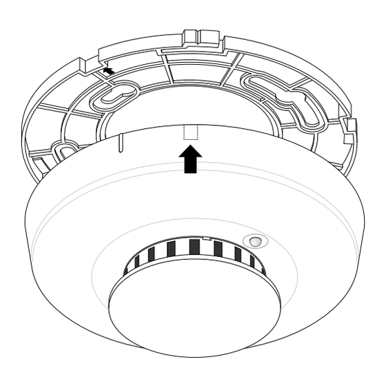
Page 2: Installing The Detector
Installing the Detector In addition to smoke detectors outside of the sleeping areas, the installation of a smoke detector on each additional story of the family All wiring must conform to the National Electric Code (NEC) living unit, including the basement, is required. These installations and/or local codes having jurisdiction. -
Page 3: Understanding The Led
Models with gaskets: Models without gaskets: 521CRXT, 528CRXT, 541C, 541CXT, 511C, 511AFT, 518C, 518AFT, 521B, 541AXT, 548C, 548CXT, 548 AXT 521BXT, 528B, 528BXT Figure 5. Detector installation 511/518/521/528 Series 2-wire wiring diagram 2-wire Device initiating circuit Listed Alarm Control Note: The 521/528 Series are polarity sensitive. -
Page 4: Cleaning The Detector
Testing the Detector Sensitivity The detector provides a sensitivity test that allows you to check the detector sensitivity using a test magnet and the LED indicator on the detector as follows: Hold the test magnet up to the raised TEST letters on the top of the detector for 2 seconds. -
Page 5: Maintaining The Detector
3 years from the date of manufacture. minimal maintenance. During the warranty period, if an Interlogix product or any of its compo- The smoke detector should be tested monthly. See Testing the nents becomes defective, it will be repaired or replaced without charge. -
Page 6: Specifications
1 second minimum Listings: 511/521/541 UL 268 518/528/548 Product Ordering Model Description 511C/518C 2-wire, photoelectric, 6.5-33VDC 511AFT/518AFT 2-wire, photoelectric, 6.5-33VDC, rate of rise heat sensor 521B/528B 2-wire, photoelectric, 6.5-33VDC 521BXT/528BXT 2-wire, photoelectric, 8.5-33VDC, multi-criteria algorithms, fixed/rate of rise heat 521CRXT/528CRXT 2-wire, photoelectric, 8.5-33VDC, aux.
Need help?
Do you have a question about the 511C and is the answer not in the manual?
Questions and answers