Advertisement
Quick Links
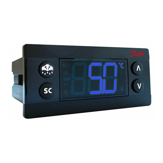
Installation Guide
ERC 112
Bottle Cooler Controller
DKRCE.PI.RL0.A2.02
520H10340
Technical specification
Power Supply
100 – 240 V AC Switch mode power supply. Average 0.7 W
5 inputs: 4 analogue (digital), 1 digital; user specific assignment
• Air / Evaporator / Condenser
• Door sensor: all types, user specific
Input
• Light sensor: Danfoss ECO light
• Motion sensor
sensor
UL60730
EN60730
120 V AC: 16 A resistive /
FLA 16/LRA 72
"DO1"
16(16) A
(Compressor relay)
240 V AC: 10 A resistive /
Output
FLA 10 / LRA 60
8 A resistive, FLA 2 / LRA
"DO4"
8 A resistive, 2(2) A
12, TV-1
"DO5"
FLA 2 / LRA 12, TV-1
8 A resistive, 2(2) A
"DO6"
FLA 2 / LRA 12, TV-1
8 A resistive, 2(2) A
Max 10 A total "DO4-6"
• Danfoss NTC sensors and Danfoss ECO accessories
Probes
• Danfoss PT1000 ohm / 0°C
• Modular connector system for OEM customers, with optional output screw
terminal adapter
Connectors
• Input connector type: Rast2 5 Edge connectors
• output connector type: RAST 5 standard
Programming
Programming with Danfoss ERC docking station, integrated system
3 types for all controls:
Assembly
front mounting; brackets; fully integrated solution
(requires OEM specific design of mounting hole)
Menu structure
1. Parameter group
Press and
hold 5 sec to
access the
menu
Lower left button
1. Parameter name
Lower left button
Scroll through parameters
Scroll through menu group
© Danfoss | DCS (az) | 2015.09
Installation guide | ERC 112
DKRCE.PI.RL0.A2.02 / 520H10340
Display
LED display, 3 digit, decimal point and multi functionality icons; °C / °F scale
Keypad
4 buttons (integrated IP65 design), 2 left, 2 right; user programmable
Operating
0 °C – 55 °C, 93% rH
Conditions
Storage
-40 °C – 85 °C, 93% rH
Conditions
Range of
-40 °C – 85 °C
Measurement
Front: IP65
Protection
Rear: water and dust protection corresponds to IP31,
accessibility of connectors limit rear part rating to IP00
Environmental
Pollution degree II, non-condensing
Resistance to
Category D (UL94-V0)
heat & fire
EMC category
Category I
Operating Cycles Compressor relay: more than 175.000 at full load (16 A (16 A))
• R290 / R600a end-use applications
employing in accordance to
EN / IEC 60335-2-24, annex CC and
EN / IEC 60335-2-89, annex BB
• Glow wire according to
• These approvals are only valid when
Approvals
EN / IEC 60335-1 / IEC / EN 60730
using the accessories approved
• UL60730
• NSF
• CQC
• GOST R 60730
Dimensions
78.25 mm
78.25 mm
82.25 mm
71 mm
71 mm
Front mounting
Rear mounting
(Lock with frame)
(Lock with clips)
Operation Changing the setpoint:
Two kinds of left buttons - see pictures 1. and 3.
Current temperature
1.
The display shows the current temperature
Flashing temperature setpoint
2.
Press: UP/DOWN to adjust setup
3.
After 30 seconds, the display automatically
reverts to showing the current temperature
Activating manual defrost
Press briefly
1.
to start or
stop defrost
Defrost symbol is shown in defrost mode
2.
^
SC
^
Defrost symbol will disappear after the defrost is
3.
finished.
^
(The dEF text during the defrost is displayed or
^
SC
not based on the cabinet manufacturer settings)
Functional description of used sensors
Control temperature sensor
The control sensor must always be connected and is used for controlling the cut-in and cut-out of
the compressor according to the set-point. The sensor is also used for the displayed temperature.
Most common placement is in the return air to the evaporator.
Evaporator sensor
The evaporator sensor is only used for de-icing of the evaporator and has no control purpose.
Place the sensor where the ice melts last.
Please be aware of that sharp fins can damage the cable.
Condenser temperature sensor
The condenser sensor is used to protect the compressor against high pressure when the
condenser is blocked or the condenser fan fails.
Place the sensor at the liquid side of the condenser. Use a metal bracket or metal tape to ensure
good thermal conductivity. Be sure that the cable does not pass hot spots at the compressor or
condenser that exceeds 80 °C.
2
1
ERC front and button functionality
Configurable functionality
Basic
Not
Increase
Decrease
Toggle
Button
ON/OFF
function
operating
setpoint
setpoint
defrost
1 press
OK
1 pess and hold
2 press
BACK
2 pess and hold
3 press
UP
3 pess and hold
4 press
DOWN
4 pess and hold
Configurable functionality
Increase
Decrease
Toggle
Toggle
Toggle °C
Button
display
display
ECO
pulldown
or F
intensity
intensity
1 press
1 pess and hold
2 press
2 pess and hold
3 press
3 pess and hold
4 press
4 pess and hold
Example of changing a parameter
1.
Press and hold 5 sec to access
the menu
2.
Press: UP / DOWN to scroll
through the menu
Scroll through parameters group
3.
To select: press the lower
left button (OK)
4.
Press: UP / DOWN to find the
desired parameter
Scroll through group "dEF" parameters
5.
To confirm: press the lower
left button (OK)
6.
Press: UP / DOWN to enter the
desired value
To accept: press the lower left
7.
button (OK) and return to
parameter name
To exit without accept:
press the upper left button (BACK)
8.
To return to parameter group:
press upper left button (BACK)
9.
After 30 seconds of inactivity,
To return to menu:
the display automatically
press upper left button (BACK)
reverts to showing the current
temperature
Wiring diagram
ERC 112D
ERC 112C
100 – 240 V AC ± 10% 50/60 Hz 0T55
100 – 240 V AC ± 10% 50/60 Hz 0T55
Outputs
Outputs
1
2
3
4
5
6
1
DO1
L
N
DO2 DO3 DO4
DO1
Inputs
Inputs
S1 S2 S3 S4 di
S1 S2 S3 S4 di
3
Configuration of outputs
4
Relay
Compress.
Defrost
Fan
outputs
Toggle
DO1 (o1C)
light
DO2 (o2C)
DO3 (o3C)
DO4 (o4C)
Configuration of inputs
Configuration of inputs
Input/
Cabinet
Evapor.
Conden.
Door
sensor
sensor
sensor
sensor
sensor
S1
S2
S3
S4
di
Info menu
Turning ON/OFF the ECO function
Press briefly to enter
1.
ECO mode
2.
ECO
Password protection
Press and hold 5
sec to access the
menu
Password protection on three levels:
LEVEL 1: shop (daily use by shop personnel)
LEVEL 2: ser (service technician)
LEVEL 3: OEM (OEM programming
Acknowledging alarm
1.
The alarm code flashing alternately
with the temperature and the
alarm symbol is displayed
2.
After the acknowledge the
temperature is displayed and the
alarm symbol remains shown
2
3
4
5
L
N
DO2 DO3
Heating
Light
Alarm
application
Light
Movem.
Comm.
sensor
sensor
The green ECO symbol is list
when in ECO mode
Press any button to acknowlege
Advertisement

Related Manuals for Danfoss ERC 112D


Summary of Contents for Danfoss ERC 112D
- Page 1 Max 10 A total "DO4-6" pulldown or F intensity intensity • Danfoss NTC sensors and Danfoss ECO accessories Probes • Danfoss PT1000 ohm / 0°C 1 press • Modular connector system for OEM customers, with optional output screw 1 pess and hold...
- Page 2 Display Intensity attached Danfoss can accept no responsibility for possible errors in catalogues, brochures and other printed material. Danfoss reserves the right to alter its products without notice. This also applies to products Minimum intensity when ambient light sensor is attached already on order provided that such alterations can be made without subsequent changes being necessary in specifications already agreed.
Need help?
Do you have a question about the ERC 112D and is the answer not in the manual?
Questions and answers