
Related Manuals for Fluke VT650


Summary of Contents for Fluke VT650
- Page 1 VT650/VT900 Gas Flow Analyzer Users Manual FBC - 0099 October 2017, Rev. 1 ©2017 Fluke Corporation. All rights reserved. All product names are trademarks of their respective companies.
- Page 2 Fluke Biomedical warrants this instrument against defects in materials and workmanship for one year from the date of original purchase OR two years if at the end of your first year you send the instrument to a Fluke Biomedical service center for calibration. You will be charged our customary fee for such calibration.
- Page 3 Copyright Release Fluke Biomedical agrees to a limited copyright release that allows you to reproduce manuals and other printed materials for use in service training programs and other technical publications. If you would like other reproductions or distributions, submit a written request to Fluke Biomedical.
- Page 4 ServiceDesk@fluke.com To ensure the accuracy of the Product is maintained at a high level, Fluke Biomedical recommends the product be calibrated at least once every 12 months. Calibration must be done by qualified personnel. Contact your local Fluke Biomedical representative for calibration.
-
Page 5: Table Of Contents
Table of Contents Title Page Introduction ....................1 Key Features ....................1 Safety Information ..................2 Unpacking and Inspection ................5 Accessories ....................6 The Analyzer ....................8 Power On the Analyzer ................. 10 Analyzer Connections ................12 Airway Flow (Inlet and Exhaust) ............ 12 Ultra-Low Flow + and - (VT900) ............ - Page 6 VT650/VT900 Users Manual Unidirectional Flow Mode ..............16 Inspiratory Flow Connections ............16 Expiratory Test Connections ............17 Operations ....................18 Measured Signals ................. 18 Airway Flow ................... 19 Airway Pressure ................19 Airway Temperature and Humidity ..........19 High Pressure ................19 Low Pressure ................
- Page 7 Contents (continued) Memory Menu ................34 Test ID ................... 34 Maintenance, Service and Calibration ............35 Cleaning ....................35 Oxygen Sensor Replacement ............... 36 Battery Status ..................36 Battery Replacement ................37 Replaceable Parts ................. 38 Service and Calibration ................. 38 Specifications ....................
- Page 8 VT650/VT900 Users Manual...
-
Page 9: Introduction
Introduction Key Features The VT650/VT900 Gas Flow Analyzer (the • Full range, bi-directional air flow and volume Analyzer or Product), is a general purpose gas channel flow analyzer with special features for testing • Ultra-low flow and pressure ranges (VT900) mechanical patient ventilators. -
Page 10: Safety Information
VT650/VT900 Users Manual Safety Information • Disable the Product if it is damaged. • Do not use the Product if it is A Warning identifies conditions and actions that damaged. pose hazards to the user; a Caution identifies conditions and actions that may damage the •... - Page 11 • Repair the Product before use if the battery leaks. To prevent possible damage, remove the O2 sensor if the Product is stored • Use only Fluke approved power in temperatures >50 °C. adapters to charge the battery. • Do not short the battery terminals together.
- Page 12 VT650/VT900 Users Manual Symbols used on the Analyzer and in this manual are explained in Table 1. Table 1. Symbols Symbol Meaning Symbol Meaning WARNING. HAZARDOUS VOLTAGE. WARNING. RISK OF DANGER. Risk of electric shock. Consult user documentation. Conforms to European Union directives.
-
Page 13: Unpacking And Inspection
Make sure you do not damage the Analyzer as damage, such as bent or broken parts, dents, you unpack. or scratches, call a Fluke Biomedical Service Center immediately. To return the Analyzer to • Inspect the shipping carton for damage. -
Page 14: Accessories
VT650/VT900 Users Manual Accessories Table 2 is a list of the standard accessories provided with the Analyzer. Table 2. Standard Accessories Item Part Number USB Serial cable 4015274 AC power adapter 4760480 Accessory kit with: 4922115 Bacterial filter for external connection to the flow ports (1) 2133712 1.2 m (4 ft) silicon tubing (2) - Page 15 Gas Flow Analyzer Accessories Table 3 is a list of optional accessories. Table 3. Optional Accessories Item Part Number Soft-sided carrying case for ACCU-LUNG 2397628 ACCU LUNG II test lung 4281291 ACCU-LUNG Lung Simulator with Soft-sided carrying 2387318 case (2397628) VESA system mount 4969657...
-
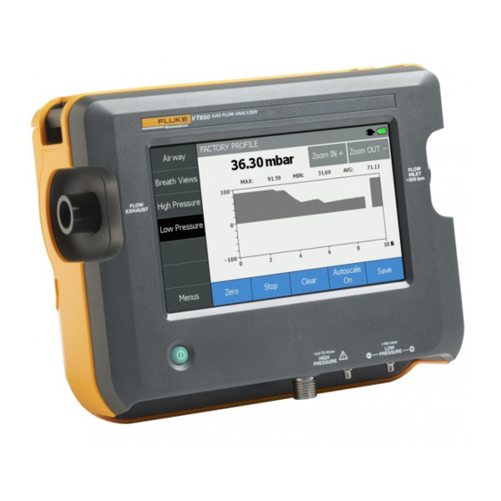
Page 16: The Analyzer
VT650/VT900 Users Manual The Analyzer Figure 1 shows the top of the Analyzer. Touchsceen LCD Flow exhaust Flow inlet VT900 GAS FLOW ANALYZER Low pressure + and - High pressure and vacuum FLOW FLOW INLET EXHAUST ±... - Page 17 Gas Flow Analyzer The Analyzer Figure 2 shows the back of the Analyzer. O2 SENSOR ACCESS DOOR Figure 2. Back of the Analyzer Handle clip External trigger input (VT900) USB port Battery status indicator Oxygen sensor door External DC power input...
-
Page 18: Power On The Analyzer
VT650/VT900 Users Manual Figure 3 shows the bottom of the Analyzer. VESA mount points (FDMI MIS-C, fits WxH of 75 mm x 35 mm) Oxygen sensor door screw Bail Battery door screws Battery door Power On the Analyzer To power on the Analyzer, push +. - Page 19 Gas Flow Analyzer The Analyzer To make a selection, tap the screen. Figure 4. Example of Airway Measurement Measurement and Other Menus Battery symbol Selected Profile Display area Measurement settings Screen options...
-
Page 20: Analyzer Connections
VT650/VT900 Users Manual Analyzer Connections • Always use the external flow filter on the main airflow channel inlet. This You can connect the Analyzer to a ventilator and helps reduce turbulence and keeps test lung in either a bi-directional or out small particles that could unidirectional flow configuration. -
Page 21: Ultra-Low Flow + And - (Vt900)
Gas Flow Analyzer The Analyzer Ultra-Low Flow + and - (VT900) High Pressure The + and - ultra-low-flow ports have a barbed The high-pressure port is primarily to test wall hose fitting connection. and tank pressurized gas sources. The connector works with standard oxygen DISS Caution fittings, as used on oxygen supply hoses. -
Page 22: Low Pressure (+ And -)
VT650/VT900 Users Manual Low Pressure (+ and -) Ultra-Low Pressure (VT900 only) Measure differential low pressure between the + The ultra-low pressure port has a barbed hose and - ports or gauge pressure on either port. fitting connection. Connectors are barbed hose fittings. -
Page 23: Test Setup
1. Use a Y-piece adapter to connect the parameters in bi-directional or uni-directional ventilator to the flow inlet on the Analyzer. modes. Fluke Biomedical recommends the bi- 2. Use a standard breathing hose to connect to directional mode. the exhaust port on the Analyzer. -
Page 24: Unidirectional Flow Mode
VT650/VT900 Users Manual Unidirectional Flow Mode Inspiratory Flow Connections Use the unidirectional flow to measure either For inspiratory connections, see Figure 6. inspiratory or expiratory gas flow. 1. Connect the inspiratory hose to the flow inlet on the Analyzer. 2. Use a standard breathing hose to connect the test lung to the exhaust port on the Analyzer. -
Page 25: Expiratory Test Connections
Gas Flow Analyzer Test Setup Expiratory Test Connections 2. Use a standard breathing hose to connect the ventilator to the exhaust port on the For expiratory connections, see Figure 7. Analyzer. 1. Connect the expiratory hose from the test The Analyzer shows the flow of gas lung to the flow inlet on the Analyzer. -
Page 26: Operations
VT650/VT900 Users Manual Operations Measured Signals The Analyzer measures these signals: Use the Analyzer to measure flow and pressure. For each test: select the test and do the setup. • Airway flow Displayed options depend on the selected test: • Airway pressure •... -
Page 27: Airway Flow
Gas Flow Analyzer Operations Airway Flow Airway Temperature and Humidity The Analyzer has a full-range flow (±300 lpm), There is a temperature / humidity sensor in the with bi-directional flow measurement. Flow airway channel on the exhaust side of the flow measurements are either static flows—no sensor. -
Page 28: Low Pressure
VT650/VT900 Users Manual Low Pressure Ultra-Low Flow (VT900) The low-pressure port is a dual-port connection The Analyzer (VT900 only) has ultra-low flow consisting of a (+) positive and a (-) negative (±750 ml/min) bi-directional flow measurement pressure port. capability. The flow measurement is for accurate, high resolution, static low flow The differential pressure range is ±160 mbar. -
Page 29: Oxygen Concentration
Table 10. bulkhead for the high-flow circuit. The oxygen Excel Add-in cell must be replaced approximately once a year (VT650) or every 2 years (VT900). Install custom Excel add-in, available for download at www.flukebiomedical.com. Use the Excel Add-in on a PC to view results data. -
Page 30: Measurements
VT650/VT900 Users Manual Measurements Save a Measurement Figure 8 is an example of the measurement The Analyzer can save readings or start a screen. recording to save. Make a Measurement To save a measurement: 1. On the measurement screen, tap Save. - Page 31 Gas Flow Analyzer Operations Figure 8. Example of Measurement Measurements Toggle manual or automatic scaling Change scaling Graph area...
-
Page 32: Main Menu Functions
VT650/VT900 Users Manual Main Menu Functions Profiles Menu Use the Main menu to access the Analyzer You can configure the settings on the Analyzer functions, including: to create test profiles. The analyzer can save up to 20 profiles. • Profiles The Analyzer stores the profiles using a numeric •... -
Page 33: Setup Menu
Gas Flow Analyzer Operations Setup Menu • *Use on Power-Up—Make the selected profile the default profile. Use the Setup menu to make and view the • Back—Go to the main Profile menu. Analyzer settings. • Edit Name—Change the name of the To setup the Analyzer, select Menus >... - Page 34 VT650/VT900 Users Manual Table 4. Setup Menu (cont.) Setup Description Sets the options for Breath Detection. Options are: • Mode - Sets the breath detection mode: Bidirectional Uni-directional Inspiratory Uni-directional Expiratory Off - disables breath triggering •...
- Page 35 Gas Flow Analyzer Operations Table 4. Setup Menu (cont.) Setup Description Displays basic information about the Analyzer including: • Date of calibration Instrument • Model number • Battery charge level Information • Serial number • Memory remaining • Firmware version Options are: •...
- Page 36 VT650/VT900 Users Manual Table 4. Setup Menu (cont.) Setup Description Options are: • Set Time Format - Select 12 hour with am/pm or 24 hour. • Set Time - Tap the arrows to set the time. If in 12-hour format, select am or pm.
- Page 37 Gas Flow Analyzer Operations Table 5. Gas Types Gas Type Description Standard room air 100 % Nitrogen 100 % Nitrous Oxide 100 % Carbon Dioxide 100 % Oxygen 100 % Argon Heliox 21 % Oxygen, and 79 % Helium Measured Oxygen, balance Nitrous Oxide O2 bal N2O mix Measured Oxygen, balance Helium O2 bal He mix...
- Page 38 VT650/VT900 Users Manual Table 6. Gas Correction Mode Gas Correction Description Ambient temperature and pressure (actual humidity) ATPD Ambient temperature and pressure, dry (0 % humidity) ATPS Ambient temperature and pressure, saturated (100 % humidity) STP20 Standard temperature 20 °C, standard pressure 760 mmHg (actual humidity) STP21 Standard temperature 21 °C, standard pressure 760 mmHg (actual humidity)
-
Page 39: Units
Gas Flow Analyzer Operations Units Table 7. Available Units of Measure (cont.) You can change the units of measure for all Unit Description readings. Volume To set the units: Liters 1. Select Menus > Units. Milliliters 2. Select the type of reading. Cubic feet 3. -
Page 40: Special Tests Menu
VT650/VT900 Users Manual Special Tests Menu Table 7. Available Units of Measure (cont.) Use the Special Tests menu for more tests. Unit Description Leak Tests calculate the lost volume over the Pressure specified time. To do a leak test: mbar millibar = 0.001 bar... -
Page 41: Calibrate Oxygen
1. Select Menus > Special Tests > Stacked to complete both steps. Volume Test. If the calibration fails, replace the Oxygen 2. Use the key pad to enter the number of sensor. If the problem persists, contact Fluke breaths. Biomedical for repair. 3. Select Start. -
Page 42: Customize Breath Views
VT650/VT900 Users Manual Customize Breath Views Test ID Use Customize Breath Views to configure Use the Test ID to identify saved test data. Use custom breath screens with up to eight readings the keyboard to enter a Test ID. When viewing each. -
Page 43: Maintenance, Service And Calibration
To remove stains and clean the special care; however it is a calibrated Analyzer, use a solution of 70 % isopropyl measuring instrument and should be treated alcohol. Fluke Biomedical does not recommend with care. any other solvents. W Caution... -
Page 44: Oxygen Sensor Replacement
The oxygen sensor can operate for longer than 12 months depending on use. With normal use The Battery status indicator on the back of the the VT650 oxygen sensor will last 12 months Analyzer has these normal states: and the VT900 oxygen sensor will last •... -
Page 45: Battery Replacement
Gas Flow Analyzer Maintenance, Service and Calibration Battery Replacement To check the battery charge level, remove the battery door and push the TEST button on the battery. The battery displays the percentage of charge. Use only the replacement battery listed in Table 8. -
Page 46: Replaceable Parts
Analyzer. annually. If the Analyzer does not operate successfully or if it needs calibration, return it to Table 8. Replaceable Parts the Fluke Biomedical Service Center, as Item Fluke Part Number indicated under Warranty and Product Support. As part of this service, hardware and software... -
Page 47: Specifications
Gas Flow Analyzer Specifications Specifications • To keep foreign debris from entering the Analyzer, use flow and pressure Specifications are based on a one year calibration cycle and apply protective caps when transporting to ambient temperature 18 °C to 28 °C unless stated otherwise. the Analyzer. -
Page 48: Pressure
VT650/VT900 Users Manual Battery Low Pressure Maximum applied Rechargeable Li-Ion Battery ......10.8 V, 2.5 Ah, 27 Wh, 3ICR19/66 pressure ......400 mbar Discharge temperature... 0 °C to 50 °C Operating Pressure.... (Differential) ±160 mbar Charge temperature ..0 °C to 40 °C Span Accuracy.... -
Page 49: Flow
Gas Flow Analyzer Specifications Flow Table 9. Airway Flow Range and Accuracy (cont.) Airway Flow Range Specification Resolution......0.01<100 slpm and 0.1 >100 slpm Carbon Dioxide (CO2), 3.0 % of rdg or Nitrous Oxide (N2O), ±150 slpm Accuracy ......see Table 9 0.08 slpm, typical O2 bal N20, Frequency Response..10 % to 90 % rise time <10 ms... - Page 50 Humidity ......% RH Oxygen concentration (Airway Flow channel) Safety Range......... 0 % to 100 % General ......IEC 61010-1: Pollution Degree 2 Accuracy ......±1 % (VT900), ±2 % (VT650) Lithium Battery ....IEC 62133 Resolution ......0.1 %...
- Page 51 Gas Flow Analyzer Specifications Electromagnetic Compatibility (EMC) International ......IEC 61326-1: Controlled Electromagnetic Environment CISPR 11: Group 1, Class A Group 1: Equipment has intentionally generated and/or uses conductively-coupled radio frequency energy that is necessary for the internal function of the equipment itself. Class A: Equipment is suitable for use in all establishments other than domestic and those directly connected to a low- voltage power supply network that supplies buildings used...
- Page 52 VT650/VT900 Users Manual Table 10. Breath Parameter Accuracy Parameter Abbreviation Resolution Range Accuracy Inspiratory Tidal Volume 0.1 ml 0 l to 60 l ±1.75 % of rdg or 0.02 l Expiratory Tidal Volume 0.1 ml 0 l to 60 l ±1.75 % of rdg or 0.02 l...
- Page 53 Gas Flow Analyzer Specifications Table 10. Breath Parameter Accuracy (cont.) Parameter Abbreviation Resolution Range Accuracy Inspiratory Time 0.01 sec 0 sec to 60 sec 0.02 sec (The time of the inspiratory period including the inspiratory hold time.) Inspiratory Hold Time 0.01 sec 0 sec to 60 sec 1 % or 0.1 sec...
- Page 54 VT650/VT900 Users Manual...
Need help?
Do you have a question about the VT650 and is the answer not in the manual?
Questions and answers