Table of Contents
Advertisement
Quick Links
Advertisement
Table of Contents

Summary of Contents for Patlite LA6-POE
- Page 1 B95100524_01 S i g n a l T o w e r Operation Manual Model LA6-POE...
-
Page 2: Table Of Contents
Signal Tower LA6-POE Operation Manual Table of Contents 1. Introduction 1.1. Safety Precautions 1.2. For safe application, observe the following: 1.3. Product Features 1.4. Trademarks 2. Model Number Configuration 2.1. Model Number Configuration 2.2. Part Names and Dimensions 3. Installation 3.1. How to Install 3.1.1. Direct-mount Type 3.1.2. Stationary Type 3.1.3. Terminal block connector (Detachment Method) - Page 3 Signal Tower LA6-POE Operation Manual 4.4.3. Read Setup Data 4.5. Main Unit Setup 4.6. Command Configuration 4.7. Modbus/TCP Setup 4.8. Contact Input Detection 4.9. Mirroring Setup 4.9.1. Setting up the Mirroring Source 4.9.2. Setup Mirroring Destination Point 4.10. Information Transmission Setup 5. Operating Procedure 5.1. PNS Command 5.1.1. Smart Mode Control Command 5.1.2. Mute Command...
- Page 4 Signal Tower LA6-POE Operation Manual 5.7. Contact Input Detection 5.8. HTTP Command Control 5.8.1. Example 5.9. Signal Tower Information Transmission Function 5.9.1. System Overview 5.9.2. Communication specifications 5.9.3. Transmission condition 5.9.4. Transmission Data Contents 5.9.5. Transmission Data Format 5.9.6. Determine Signal Tower Input 5.9.7. Maintain Signal Tower Status 5.9.8. Visualization Application Software 6.
-
Page 5: Introduction
Notice • The copyrights of this book is owned by the PATLITE Company, Inc. (henceforth referred to as "our company"). Any reproduction, duplication, alteration, or extracting portions of this book, etc., without written permission from our company is forbidden. -
Page 6: For Safe Application, Observe The Following
Signal Tower LA6-POE Operation Manual 1.2. For safe application, observe the following: WARNING To prevent from shock, short-circuits or damage, observe the following: • Be sure the power is disconnected before replacement (fuse exchange, etc.) or repair. • Use this product in a properly maintained condition. (Replace or repair if the body, LED unit, etc. are damaged.) Request the installation and wiring be performed by a professional contractor if construction work is involved. -
Page 7: Model Number Configuration
Signal Tower LA6-POE Operation Manual 2. Model Number Configuration 2.1. Model Number Configuration Rated Mounting Body Flashing/ Extended Model Tiers Voltage Specifications Color Buzzer Functionality Model LA6- -P OE ↓ Number Common to all models Common to all models Rated voltage: DC24V. -
Page 8: Part Names And Dimensions
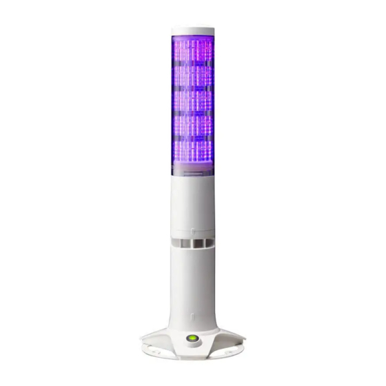
Signal Tower LA6-POE Operation Manual 2.2. Part Names and Dimensions <LA6-5DTNWB-POE> <LA6-5DSNWB-POE> φ60 Headcover (Multi-function Button Inside →※1) LED Unit USB Cover (In Back) ※2 LAN Unit Nameplate (Backside) “Clear” Switch Stand Cover LAN Bracket φ60 Base Plate (Unit: mm) Maximum Board thickness: 4 mm ※... -
Page 9: Installation
Signal Tower LA6-POE Operation Manual 3. Installation CAUTION The clamping surface should be sufficient enough to tolerate the weight and surface of the product. Do not use the product in a place where vibrations exceeds the specifications. Failure to comply may result in the prevention of the product detaching and falling, causing injury to a passer-by, etc. -
Page 10: Stationary Type
Signal Tower LA6-POE Operation Manual 3.1.2. Stationary Type ❶ Loosen the screw to remove the bottom LAN Unit plate. (Do not completely remove the screw.) Terminal Block Connector LAN Cable ❷ The lock on the terminal block connector can be unlocked and removed for wiring. -
Page 11: Terminal Block Connector (Detachment Method)
Signal Tower LA6-POE Operation Manual 3.1.3. Terminal block connector (Detachment Method) <Removing> <Attaching> ※ The example figure shows the TN model. 〈Figure of LAN unit from the underside〉 Raise the lever Terminal block connector Referring to the drawing, depress the lever... -
Page 12: Wiring Example
3.2.3. Wiring Example The following is a basic wiring example. If there are any special applications that require asking questions concerning this product, feel free to contact your PATLITE Sales Representative. * When lighting and flashing are used together in the Signal Tower mode with a PLC, it is necessary to separate the flashing and non-flashing circuit outputs on the PLC side. - Page 13 Signal Tower LA6-POE Operation Manual 3.2.3.2. Connecting to a PLC (NPN Type Transistor) with DC24V Input For Flashing/ Power Pulse Enable Output Unit 2 24VDC Input Do Not Apply Voltage! LA6-POE External Contact Classi cation PLC (NPN Transistor) Flashing/Pulse Enable ⑪...
-
Page 14: Lan Cable Connection
Signal Tower LA6-POE Operation Manual 3.2.3.4. Connecting to Contact Relay with PoE Input 〈 Note 〉 Since ashing and Pulse LA6-POE Power Enable Common are uncontrollable for a PoE PoE Input input, do not connect it. External Contact Classi cation... -
Page 15: How To Operate
• Use the Web Setup Screen to set up. (Refer to “4.4.2 WEB Setup” on page 22) ③ Load the Setup Data information into the LA6-POE. • Use the Web Setup Screen to load the data. (Refer to “4.4.1 Loading Setup Data” on page 20) ④ ... -
Page 16: When Mirroring
(Refer to "4.9.2 Setup Mirroring Destination Point" on page 30) 4.1.4. When Collecting the Signal Tower Information [ Retrieving the Signal tower information submitted by a LA6-POE ] ① Set up the LA6-POE network. • Set the IP address for the network. (Refer to “4.3 Network Setup” on page 19) ② Set up the LED unit colors and combinations. - Page 17 Signal Tower LA6-POE Operation Manual [ Send a command to LA6-POE and collect information ] ① Set up the LA6-POE network. • Set the IP address for the network. (Refer to “4.3 Network Setup” on page 19) ② Set up the LED unit colors and combinations.
-
Page 18: Web Setup Screen
Recommended Browsers: Internet Explorer 11, Google Chrome When the login screen is displayed, enter "patlite" in the password field, then click the "Login" button. The default password is "patlite", all in lower case letters. Be sure to change the password to prevent any security breaching. -
Page 19: Network Setup
Signal Tower LA6-POE Operation Manual 4.3. Network Setup The network parameters for this product can be setup through a browser. The default IP address is "192.168.10.1". The items that can be set up through the System Setup Screen is as follows for "Network Setup."... -
Page 20: Led Unit Setup
Signal Tower LA6-POE Operation Manual 4.4. LED Unit Setup This product can control the Signal Tower in two modes, Signal Tower mode and smart mode. ■ Signal Tower Mode It is a mode to set the tone color of each LED tier and buzzer in advance for this product and control it by the signal line and commands. - Page 21 Signal Tower LA6-POE Operation Manual [Data writing method in "EDITOR for LA series"] ① The product changes to standby status (all signal inputs OFF). (Power supply input can be ON or OFF, whichever is easier) ② Open the USB cover to the product, use the MicroUSB cable to connect the product to the personal computer.
-
Page 22: Web Setup
Signal Tower LA6-POE Operation Manual 4.4.2. WEB Setup On the "Signal Tower Mode" screen, select the LED lighting color, buzzer sound and flashing speed. Default Input Item Contents Setup Option Value Parameter Signal Tower 1 × Select among: Signal Tower 2 YELLOW ×... -
Page 23: Read Setup Data
Click the "Read" button for reading the LED unit setting data and save it on a personal computer. The setting data of the read LED unit can be written to another LA6-POE, and the contents can be checked with the “EDITOR for LA series”. -
Page 24: Main Unit Setup
Signal Tower LA6-POE Operation Manual 4.5. Main Unit Setup The buzzer volume and the control method can be set up. The LED unit setup data can be synchronized. Input Setup Item Contents Default Value Parameter Option Buzzer Sound Select among 0 (Mute), 1, 2, and 3 (Maximum). -
Page 25: Command Configuration
Signal Tower LA6-POE Operation Manual 4.6. Command Configuration Set up for receiving PNS and PHN Commands. [Setup Method] ① Select either "TCP" or "UDP" in "Protocol." ② Enter the port to be used for "Port Number." ③ Click the "Set" button to apply the setting. -
Page 26: Modbus/Tcp Setup
Signal Tower LA6-POE Operation Manual 4.7. Modbus/TCP Setup Set the port number to be used in Modbus/TCP. [Setup Method] ① Enter the port to be used for "Port Number." ② Click the "Set" button to apply the setings. Default Item Contents Input Parameter... -
Page 27: Contact Input Detection
Signal Tower LA6-POE Operation Manual 4.8. Contact Input Detection It detects the status change of the contact input and perform the set-up process. The setup for the contact input detection is done in the Web Setup. ① Set the action to be executed when the setting input status 1 to 4 changes. -
Page 28: Mirroring Setup
Status Change Up to nine LA6-POE Signal Towers can be in the same status by sending the status of the LA6-POE which is being controlled by the Master via the signal line, to another one of eight LA6-POE Signal Towers connected within the network. -
Page 29: Setting Up The Mirroring Source
Signal Tower LA6-POE Operation Manual 4.9.1. Setting up the Mirroring Source In the "Main Unit Setup" screen, set the Control-system Switchover to the signal wire control method. Register the IP address of the mirroring destination in the "Mirroring Setup" screen. -
Page 30: Setup Mirroring Destination Point
Signal Tower LA6-POE Operation Manual 4.9.2. Setup Mirroring Destination Point In the "Main Unit Setup" screen, set the control method to the command control method. CAUTION To mirror, set the same LED unit in the mirroring source and mirroring destination. -
Page 31: Information Transmission Setup
Signal Tower LA6-POE Operation Manual 4.10. Information Transmission Setup Set the Destination Address of the signal tower information, signal tower input judgment,smart-mode information to send. 1 Attach the lead wires. "3.2. Wiring" on page 11 2 Attach the LAN cable. -
Page 32: Operating Procedure
Signal Tower LA6-POE Operation Manual 5. Operating Procedure 5.1. PNS Command By sending PNS commands from a PC etc., you can control and obtain the status of this product. The protocol can be selected from “TCP” or “UDP.” Communication port numbers are “10000-65535.”... -
Page 33: Smart Mode Control Command
Signal Tower LA6-POE Operation Manual 5.1.1. Smart Mode Control Command Command Description The Smart Mode can be executed with the number specified in the data area. Transmission Data Format Product Category Identifier Data Area Open Data Size 1 byte See Below Product Category The product is classified in “AB. -
Page 34: Mute Command
Signal Tower LA6-POE Operation Manual 5.1.2. Mute Command Command Description The ON/OFF of the buzzer is controllable when executing in Smart Mode. Transmission Data Format Product Category Identifier Data Area Open Data Size 1 byte See Below Product Category The product is classified in “AB. ”... -
Page 35: Stop/Pulse Input Command
Signal Tower LA6-POE Operation Manual 5.1.3. STOP/Pulse Input Command Command Description When transmitting during the time trigger mode operation, the pattern stop/restart can be controlled. (STOP Input) When transmitting during the pulse trigger mode operation, the pattern can be changed. (Pulse Trigger Input) -
Page 36: Managing Command Control
Signal Tower LA6-POE Operation Manual 5.1.4. Managing Command Control Command Description Each LED unit tier and buzzer (1-3) can be controlled with the pattern specified in the data area. It operates with the color and buzzer set up in the Signal Tower mode. -
Page 37: Managing Detailed Command Control
Signal Tower LA6-POE Operation Manual 5.1.5. Managing Detailed Command Control Command Description In the data area, the color and behavior pattern of each LED unit tier and buzzer pattern (1 to 11) can be controlled when being specified. Transmission Data Format... -
Page 38: Clear Command
Enter the password which is set up in the password setting of the Web Setup as an ASCII code. Reply Data Normal Response (1 byte) Abnormal Response (1 byte) Command Response Example When the password is set to “patlite”. Data Area Product Category Identifier Open... -
Page 39: Status Acquisition Command
Signal Tower LA6-POE Operation Manual 5.1.8. Status Acquisition Command Command Description The status of the signal line/contact input, the LED unit and buzzer status can be acquired. Transmission Data Format Product Category Identifier Open Data Size Product Category The product is classified in “AB. ”... - Page 40 Signal Tower LA6-POE Operation Manual Abnormal Response (1 byte) Command Response Example Conditions are; Inputs 1, 3, 5, and 8 are ON, smart mode group number: 5, mute input: ON, STOP input: OFF, pattern number: 15. 1 byte 2 byte 3 byte 4 byte 5 byte 6 byte 7 byte 8 byte 9 byte 10 byte 11 byte 12 byte 13 byte 14 byte...
-
Page 41: Detailed Status Acquisition Command
Signal Tower LA6-POE Operation Manual 5.1.9. Detailed Status Acquisition Command Command Description The following information can be acquired. ・ The status of the signal line/contact input. ・ The LED unit status. ・ The LED unit color information. ・ The MAC address of this product. - Page 42 Signal Tower LA6-POE Operation Manual [ Normal Response (45 bytes): When running in Smart Mode ] 1 byte 2 bytes 3 bytes 4 bytes 5 bytes 6 bytes 7 bytes 8 bytes 9 bytes 10 bytes 11 bytes 12 bytes 13 bytes 14 bytes...
- Page 43 Signal Tower LA6-POE Operation Manual ■ Command Response Example 1 [ MAC address of this machine] 80:39:E5:00:1A:2F [Mode] Signal Tower Mode [LED unit] 1st Tier: Red On, 2nd Tier: Yellow On, 3rd Tier: Green Flashing, 4th Tier: Blue On, 5th Tier: White Flashing...
-
Page 44: Phn Command
Signal Tower LA6-POE Operation Manual 5.2. PHN Command By sending a PHN command from a personal computer, it is possible to turn on and flash the LED unit tiers 1 to 3, and control buzzer patterns 1 and 2. The protocol can be selected from “TCP” or “UDP. ”... - Page 45 Signal Tower LA6-POE Operation Manual Read Command Data can be transmitted in the following format to request the current operating status for the LED unit tiers 1-3 (from the top) and buzzer. "R" (52H) 8 bit Reply Data Operation Data 8 bit...
-
Page 46: Modbus/Tcp
Signal Tower LA6-POE Operation Manual 5.3. Modbus/TCP This product can be controlled and obtain its status by transmitting a command from the master that is corresponding to Modbus/TCP protocol. The communication port numbers are “502, 1024-65535. ” • The setup of the Modbus/TCP can be done by the Modbus/TCP settings. (Refer to "4.7. -
Page 47: Register Address
Signal Tower LA6-POE Operation Manual 5.3.3. Register Address The register address list supported by this product. Register Address Control Allocation Data Condition 00H: doesn't control, 01H: controls 1 (01H) 1st LED Unit Tier 00H: OFF, 01H : ON, 02H: flashing, 09H: No Change... -
Page 48: Command Transmission Example
Signal Tower LA6-POE Operation Manual Coil/Register Numbers Register Address Control Allocation Example Data Integer Does Control, Steady on: 0101H = 257 40001 1 (01H) 1st LED Unit Tier Does Control, Flashing: 0102H = 258 Does Control, Steady on: 0101H = 257... - Page 49 00H 00H 00H 00H Diagnostic Sub-code : 00H 00H Fixed Data : 00H 00H Fixed Reply Command When the LA6-POE control board inside the Signal Tower can be turned on. Data Transaction Protocol Field Length Unit Identifier Function Code Diagnostic...
- Page 50 Signal Tower LA6-POE Operation Manual <Write Multiple Registers (10H)> Control Command Where the 1st Signal Tower tier is on, the 2nd tier is flashing, the 3rd tier has no change, the 4th and 5th tiers are off, and buzzer pattern 2 is sounding.
-
Page 51: Mirroring
5.4. Mirroring Up to nine LA6-POE Signal Towers can be in the same status by sending the status of the LA6-POE which is being controlled by the Master via the signal line, to another one of eight LA6-POE Signal Towers connected within the network. -
Page 52: Signal Wire Control
Signal Tower LA6-POE Operation Manual 5.5. Signal Wire Control This product has two methods of control, by a signal line input or controlling by commands. This item describes the control method by a signal line. There are two kind of signal line control modes, "Signal Tower Mode" and "Smart Mode". Switching between the "Signal Tower Mode"... -
Page 53: Smart Mode
Signal Tower LA6-POE Operation Manual 5.5.2. Smart Mode There are three kind of modes, "Time-trigger Type", "Pulse Trigger Type", and "Single-display Type". The main mode has common functions for each type and has the following at this mode. <Input 6 (Mute input)>... - Page 54 Signal Tower LA6-POE Operation Manual <Operation Example> The following are examples of the time trigger type operation. In addition to time progress and pattern changes, the figure also shows the mute input operation. [Group/Pattern No.] 1/4 1/5 Operating 1/1 1/2 1/3...
- Page 55 Signal Tower LA6-POE Operation Manual 5.5.2.2. Pulse Trigger Type Pattern transition is changed by a pulse trigger (one shot pulse) input. A pulse trigger is entered using input 5. Execute up to a maximum of 15 groups, with inputs 1-4.
- Page 56 Signal Tower LA6-POE Operation Manual <Operation Example> The following are examples of the pulse trigger type operation. In addition to trigger input and pattern changes, the figure below shows the operation of the mute input. [Group/Pattern No.] Operating - - -...
- Page 57 Signal Tower LA6-POE Operation Manual 5.5.2.3. Single-display Type Execute 31 registered pattern selections with inputs 1 to 5. <Input- Group Compatibility Table> For inputs 1-5, Pattern numbers in combination of ON/OFF can be put into the diagram. Pattern Pattern Input 1 Input 2 Input 3 Input 4 Input 5 Input 1 Input 2 Input 3 Input 4 Input 5 An empty cell indicates the “OFF”...
-
Page 58: Input Signal Time Chart
Signal Tower LA6-POE Operation Manual <Operation Example> The following are examples of the single display type operation. [Group/Pattern No.] Pattern 10 Pattern 21 Operating Pattern 1 Pattern 2 Clear Pattern 1 Status Buzzer Mute Mute Mute Mute Input 1 Input 2... -
Page 59: Clear" Function
Signal Tower LA6-POE Operation Manual 5.6. "Clear" Function This product can be cleared by using the "Clear" function. The clear function only operates while using the command control method. • The Clear status indicates the following status: • To turn an LED Unit OFF •... -
Page 60: Contact Input Detection
Signal Tower LA6-POE Operation Manual 5.7. Contact Input Detection Use the contact inputs 1-4 to perform the operation set up by operating the contacts. The operation can be selected from "No operation", "Clear", "mute", "STOP", and "Trigger". (Refer to “4.8 Contact Input Detection” on page 27) - Page 61 Signal Tower LA6-POE Operation Manual <Operation Example> Execute in smart mode (Time-trigger Type) with identifier "T" in a PNS Command. Operating 1/1 1/2 - - - 1/60 1/61 STOP 1/61 1/62 1/63 Status Buzzer Mute MUTE Smart Mode Smart Mode running...
-
Page 62: Http Command Control
Signal Tower LA6-POE Operation Manual 5.8. HTTP Command Control This product can be controlled by transmitting a HTTP command from the HTTP client. [Specification of HTTP command control] Protocol HTTP Method Syntax http://<IP address>/api/control?<parameter name>=<value>[&<parameter name>=<value>] Response Success. The parameter name is correct. -
Page 63: Example
Signal Tower LA6-POE Operation Manual 5.8.1. Example <alert> 1st Tier : lighting, 2nd Tier / 3rd Tier : flashing, 4th Tier : Off, 5th Tier : No Change, Buzzer : Pattern 1 http://192.168.10.1/api/control?alert=122091 <smart> Smart Mode group 10 is executed. -
Page 64: Signal Tower Information Transmission Function
Transmit Signal Tower information 5.9.2. Communication specifications LA6-POE will automatically TCP connection to the receiver (ex: Visualization application software) , and Signal Tower Information is transmitted when status changes occurs. Automatic reconnection every 3 seconds when LA6-POE cannot connect or disconnect to receiver. -
Page 65: Transmission Data Format
Signal Tower LA6-POE Operation Manual 5.9.5. Transmission Data Format Data Format Product Category Identifier Open Data Size Data Area 20H or 25H See Below Product Category The product is classified in “AB. ” Identifiers 00H is fixed. Data Size The number of bytes for the data area is stored. - Page 66 Signal Tower LA6-POE Operation Manual << When running in Smart Mode >> MAC address Mode Time counter Open Packet No. The MAC address of this product is stored. 01H : 0000H - FFFFH 00H - FFH Smart mode Smart Mode Status Group No.
-
Page 67: Determine Signal Tower Input
Signal Tower LA6-POE Operation Manual 5.9.6. Determine Signal Tower Input There are two types of decisions for signal tower inputs, Normal and Flashing. If there is no flashing state, use "Normal". Setting Determination Description When the signal input status changes from "Light off" to "Light on", the result is Light on "light on"... - Page 68 Signal Tower LA6-POE Operation Manual The status and determination operations are as follows. (Information in square brackets “[ ]” represent buzzer operation.) Description Setting Determination Change in state Operation result Light on [buzzer on] Input Light off [buzzer off] Light off → Light on...
-
Page 69: Maintain Signal Tower Status
■ Detailed Status Acquisition Command. LA6-POE Visualization Application Software (Server) (Client) Transmit Acquisition Commnad Transmit the latest Signal Tower Receive the latest Signal Tower information information Visualize data MEMO When using software packages from PATLITE partners, please contact our sales office. -
Page 70: Maintenance
Signal Tower LA6-POE Operation Manual 6. Maintenance 6.1. Initialization Please proceed following steps when it is required for initialization. When you want to return to the factory settings. When you forget the IP address of this product. When you forget the Login Password of this product. - Page 71 Signal Tower LA6-POE Operation Manual Blue Flashing Red Flashing Push Push Push ab .15sec. ab .5sec. ab .5sec. Select the ab 3sec. Select the ab 3sec. ab 3sec. contents contents and decide. and decide. Initialization network settings Initialize setting items...
-
Page 72: Reboot
Signal Tower LA6-POE Operation Manual 6.2. Reboot Please proceed following steps when it is required for initialization. Mirroring does not display. Cannot operate Socket Communication. Rebooting this product can be done by the following methods. • Reboot in the Web setting Screen. -
Page 73: Web Login Password Change
Signal Tower LA6-POE Operation Manual 6.3. Web Login Password Change The password can be changed in the Web Setting Screen. The password is used for the following applications. • Log in to the Web Setting Screen. • Adding to a Reboot command. -
Page 74: Version Confirmation
Signal Tower LA6-POE Operation Manual 6.4. Version Confirmation The version of this product can be checked by the following methods. • Operate the Multi-function button to confirm. • Check in the Web Setting Screen. This product has an LED unit section and LAN unit section, in which each version is available separately. -
Page 75: Normal Operation
Signal Tower LA6-POE Operation Manual [How to check the LED unit section version with the Multi-function button] Press for about 3 seconds. LED color change Normal Operation Version confirmation When the Multi-function button is pressed for about 3 seconds and released, the LEDs on all the tiers flicker in green and the LED color change and version can be checked. - Page 76 Signal Tower LA6-POE Operation Manual To verify the firmware version, three LED tiers will light up in accordance to the current firmware version, indicated from top to bottom. Refer to the following table for the meaning of each LED color.
-
Page 77: Led Color Change
Signal Tower LA6-POE Operation Manual 6.5. LED Color Change The LED color can be changed from that of the default color when operating in the “Signal Tower Mode” and the Multi- function button for this product is pressed. Press for about 3 seconds. - Page 78 Signal Tower LA6-POE Operation Manual <LED Color Change> The LED color which operates in the Signal Tower mode can be changed. First, the LED color change starts from the1st tier where the red LED turns on. As shown in the figure below, whenever the Multi-function button is pushed for a short time (Ab. 0.5 sec.), the 1st tier of the LED lighting color changes in order.
-
Page 79: Buzzer Sound Control
Signal Tower LA6-POE Operation Manual 6.6. Buzzer Sound Control There are two ways to adjust the buzzer sound volume for this product; using the Web setting method and setting the button operation method. Refer to “4.5 Main Unit Setup” on page 24 for the method to set up via the Web Setting Screen. -
Page 80: Language Data Update
Signal Tower LA6-POE Operation Manual 6.7. Language Data Update This product can display up to two languages on the Web Setting Screen. The default language is "English", but the language can be selected to display "Japanese". By uploading language data to this product from the login screen, the language displayed in the Web setting screen can be changed. -
Page 81: Firmware Update
Signal Tower LA6-POE Operation Manual 6.8. Firmware Update 6.8.1. Firmware update of the LED unit The firmware can be updated in the Web Setting Screen. [Update Method] ① Log into the Web Setting Screen. ② Select “Firmware Update” from the menu items. -
Page 82: Firmware Update Of The Lan Unit
Signal Tower LA6-POE Operation Manual 6.8.2. Firmware update of the LAN unit The firmware can be updated in the Web Setting Screen. [Update Method] ① Log into the Web Setting Screen. ② Select “Firmware Update” from the menu items. ③ In “Update LAN Unit“, Click the “Browse“ button to select the firmware of the LAN unit. -
Page 83: Troubleshooting
If trouble is encountered while using this product, check the table below for applicable items and implement the contents described in "Cause / Countermeasure". If there is no applicable explanation, or if the "Cause/Countermeasure" can not be solved, contact your nearest PATLITE Sales Representative listed at the end of this book. Problem... - Page 84 Signal Tower LA6-POE Operation Manual Problem Cause/Countermeasure Reference Is the buzzer sound set to "Mute"? “6.6 Buzzer Sound Control”, pg. Set the buzzer sound to an audible level. Is the "Buzzer: No sound" selected in the smart mode setting? “EDITOR for LA series” help Set up the desired buzzer pattern.
- Page 85 Signal Tower LA6-POE Operation Manual Problem Cause/Countermeasure Reference Are you logged in the Web Setting Screen? Please log out the Web Setting Screen. The HTTP command cannot be controlled. Is the control method set to the signal wire control method? “4.5 Main Unit Setup”, pg.
-
Page 86: Replacement Parts
Signal Tower LA6-POE Operation Manual 8. Replacement Parts The replacement parts list for this products is shown in the table below. When replacement parts are necessary, direct your inquiries to the store where this product was purchased. Head Cover USB Cover Waterproofing Ring B (2 pc. -
Page 87: Option Parts
Signal Tower LA6-POE Operation Manual 9. Option Parts 9.1. Wall-mount Bracket (Direct Mounting Type [TN]) Supported Option Model SZK-003W ❶ Place the product (LA 6 - 5 DTNWB - POE) directly onto the wall-mount bracket (SZK - 003W) as shown on the left. -
Page 88: Wall-Mount Bracket (Stationary Type [Sn])
Signal Tower LA6-POE Operation Manual 9.2. Wall-mount Bracket (Stationary Type [SN]) Supported Option Model NH-WST2 ❶ Use 4 M5 screws (or equivalent) to mount the Wall-mount Wall-mount Bracket (NH - WST 2). Bracket Adjust the bolting torque in accordance with the quality of the surface material of the wall, or the screw length. -
Page 89: General Specifications
Signal Tower LA6-POE Operation Manual 10. General Specifications LA6-5DTNWB-POE Model DC24V Rated Voltage DC48V Power over Ethernet (PoE) DC24V ±10% Operating Voltage Range DC36 - 57V Power over Ethernet (PoE) DC24V supply: 0.30A; PoE at DC48V supply: 0.18A ※ 1 Typ. - Page 90 Signal Tower LA6-POE Operation Manual Model LA6-5DTNWB-POE Red (1000mcd), Amber (1700mcd), Green (2600mcd), Blue (1000mcd), White (1250mcd) Luminous Intensity (typ) ※ 3 Purple (800mcd), Pink (850mcd), Lemon (2150mcd), Sky blue (2150mcd)” “30±2 Flashes Per Minute, 60±2 Flashes Per Minute, 120±2 Flashes Per Minute (Factory Flashing Rate Default: 60 Flashes Per Minute) Switchable by Web setup tool”...
- Page 91 Signal Tower LA6-POE Operation Manual Model LA6-5DSNWB-POE DC24V Rated Voltage DC48V Power over Ethernet (PoE) DC24V ±10% Operating Voltage Range DC36 - 57V Power over Ethernet (PoE) DC24V supply: 0.30A; PoE at DC48V supply: 0.18A ※ 1 Typ. Rated Current Consumption DC26.4V supply: 0.49A;...
- Page 92 Signal Tower LA6-POE Operation Manual LA6-5DTNWB-POE Model Red (1000mcd), Amber (1700mcd), Green (2600mcd), Blue (1000mcd), White (1250mcd) Luminous Intensity (typ) ※ 3 Purple (800mcd), Pink (850mcd), Lemon (2150mcd), Sky blue (2150mcd)” “30±2 Flashes Per Minute, 60±2 Flashes Per Minute, 120±2 Flashes Per Minute (Factory Flashing Rate Default: 60 Flashes Per Minute) Switchable by Web setup tool”...
- Page 93 Signal Tower LA6-POE Operation Manual ■ Correspondance tabele of RGB color model Color Number Image RGB color mode r ed #FF0000 #FF3300 #FF6600 #FFAA00 yellow #FFCC00 #FFEE00 lemon #EEFF00 #CCFF00 green #00FF00 #00FF66 skyblue #00BBDD #0099EE blue #0033FF #6699EE #9966EE...
- Page 94 Signal Tower LA6-POE Operation Manual - Specifications may change without notice due to continual product improvement. - PATLITE and the PATLITE logo is a trademark, or registered trademark of the PATLITE Corporation of Japan and each country. - Windows is a registered trademark of the U.S. Microsoft Corporation in the U.S. and other countries.
Need help?
Do you have a question about the LA6-POE and is the answer not in the manual?
Questions and answers