
Related Manuals for Triplett 2000


Summary of Contents for Triplett 2000
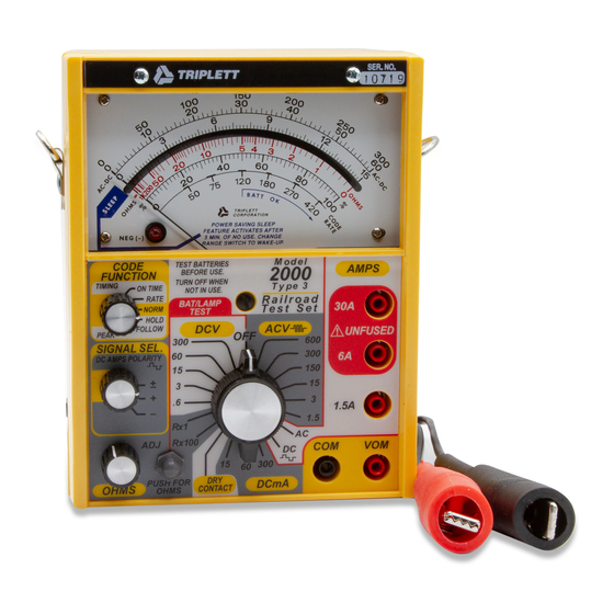
- Page 1 TRIPLETT 2000 Series Type 3 Railroad Test Sets Instruction Manual Model 2000 Model 2001 Model 2002 Model 2003 84-873 7/07 1.800.561.8187 information@itm.com www. .com...
-
Page 2: Safety Rules
SAFETY RULES Warning This Tester has been designed with your safety in mind. However, no design can completely protect against incorrect use. Electrical circuits can be dangerous and/or lethal when lack of caution or poor safety practices are used. Read the Manual Read this Instruction Manual carefully and completely. - Page 3 Don't Touch Don't touch exposed wiring, connections, or other "live" parts of an electrical circuit. If in doubt, check the circuit first for voltage before touching it. Turn off the power to a circuit before connecting test probes to it. Be sure there is no voltage present before you touch the circuit.
-
Page 4: Table Of Contents
TABLE OF CONTENTS SAFETY RULES INTRODUCTION PRODUCT FEATURES Code Measurements The Cab Filters Auto-Polarity Power Supply Features PREPARATION FOR USE Meter Mechanical Zero Visual Inspection of the Test Set Visual Inspection of the Test Leads Battery and Fuse Test Battery and Fuse Replacement Page 4 1.800.561.8187 information@itm.com... - Page 5 GENERAL OPERATION OPERATION Measuring AC and DC Voltage Measuring DC milliAmps Measuring DC and AC Amps Measuring Resistance Measuring Dry Contacts Measuring DC Pulse Code Signals SPECIFICATIONS Electrical Specifications Physical Specifications ACCESSORIES, PARTS, AND SERVICE LIMITED WARRANTY Page 5 1.800.561.8187 information@itm.com www.
-
Page 6: Introduction
Two, 9V Alkaline Batteries One, D-cell Alkaline Battery Product Description The Model 2000 Series of Railroad Test Sets are specialized VOM's designed for measuring the signal parameters of railroad coding equipment. They maintain compatibility with older technologies, while at the same time, offering functions and features not found on standard VOM's. -
Page 7: Model
Four Models The 2000 Series currently consists of four models. The base Model 2000 has all the features mentioned above with the exception of the Cab Filters. The Model 2001 includes selectable 100 Hz and 250 Hz Cab Filters. The Model 2002 includes selectable 100 Hz and 200 Hz Cab Filters. -
Page 8: Product Features
NEG Indicator. For the Dry Contact Range, Peak Hold will cap- ture and hold a momentary contact closure. CAUTION: The 2000 Series Type 3 will continue to read out the averaged value of the last captured measurements, even after the signal has been removed. - Page 9 No averaging is performed, so if the peak level is varying, the Pointer will follow it. WARNING: The 2000 Series Type 3 will continue to read out the value of the last captured measurement, even after the signal has been removed.
-
Page 10: The Cab Filters
The Cab Filter If the Test Set has Cab Filters, then all AC functions may select one frequency to be measured. This is invaluable when multiple cab signals are being sent, as it negates the need to turn off one of the cab signals to measure the other one. - Page 11 2.4.2 Battery Monitor To prevent operation of the Test Set with weak batteries, a battery test is performed every time the Range Switch is changed. If the batteries are low, the Pointer will deflect down scale into the Sleep Zone. It will not respond to any input making measurements impos- sible.
-
Page 12: Preparation For Use
PREPARATION FOR USE Before using the Test Set, familiarize yourself with the instrument and this manual. READ AND REVIEW THIS MANUAL FREQUENTLY. Each time the Test Set is used, check, and if necessary, correct the mechanical zero of the meter. Refer to Section 3.3. Inspect the Test Set for mechanical defects as described in Section 3.4. -
Page 13: Meter Mechanical Zero
Meter Mechanical Zero 3.3.1 Place the Test Set on its back on a flat, horizontal surface. Set the Range Switch to the OFF position. 3.3.2 Examine the position of the Pointer on the Dial. If it is ex- actly on the Zero Mark, then the meter is mechanically zeroed and no adjustment is necessary. -
Page 14: Visual Inspection Of The Test Set
Visual Inspection of the Test Set Before use, inspect the Test Set for any conditions which would make it unsafe. Check for missing or loose parts ( knobs, screws, or insulators ). Check also for damage, such as cracks, chips and burn marks. -
Page 15: Battery And Fuse Test
Battery and Fuse Test Before using the Test Set, and frequently during use, the batteries and fuses in the Test Set should be tested. Refer to Section 3.7 for instructions on installing and/or replacing the batteries and fuses if necessary. 3.6.1 9V Battery Test Place the Test Set Range Switch in the OFF position. - Page 16 3.6.2.1 VOM Fuse Test Place the Test Set Range Switch in the DRY CONTACT position. Place the Code Function switch in the NORM position. Connect the test leads to the instrument. The red lead is attached to the VOM Jack and the black lead to the COM Jack. Short the leads, and the Pointer must deflect to full scale.
- Page 17 3.6.3 D-cell Battery Test Place the Test Set Range Switch in the Rx1 position. Short the test leads together (they must be in the VOM and COM jacks). Depress the Push For Ohms Switch and, using the Ohms Adjust Control, attempt to set the Pointer to full scale deflection.
-
Page 18: Battery And Fuse Replacement
Battery and Fuse Replacement 3.7.1 Case Back Removal 3.7.1.1 Disconnect any test leads connected to the Test Set and place the Range Switch in the OFF position. 3.7.1.2 Remove the case back by turning the large thumb screw in the center of the case back counter clockwise. 3.7.2 Battery Replacement 3.7.2.1 Remove the D-cell and two 9V alkaline batteries under the... - Page 19 3.7.3 Fuse Replacement 3.7.3.1 Locate the two fuses on the Input Scaling Board (BD200). 3.7.3.2 Using a small, flat blade screwdriver, gently lift the installed fuse from its clips. Be careful so as not to bend the fuse clips. 3.7.3.3 Install a new fuse of the proper type. See Section 7.4 for the correct type.
-
Page 20: General Operation
This section describes general operation of the Test Set. When making measurements of any type, refer to this section. THE MODEL 2000 SERIES RAILROAD TEST SETS ARE INTENDED FOR USE ONLY BY PERSONNEL TRAINED IN THE PROPER SAFETY PROCEDURES AND WHO CAN RECOGNIZE SHOCK AND SAFETY HAZARDS. - Page 21 4.2.3 While holding the insulated boot covering the alligator clip, touch the alligator clips to the circuit being tested. If no voltage is present, connect the alligator clips to the points to be measured. If a voltage is found, check the equipment to make certain that all power is off and all capacitors are discharged.
-
Page 22: Operation
OPERATION Measuring AC and DC Voltage 5.1.1 Refer to Section 3.0, Preparation For Use, and Section 4.0, General Operation, before attempting any measurements. 5.1.2 Select the desired AC or DC voltage range by rotating the Range Switch to the desired range. If measuring AC voltage with a Test Set with Cab Filters (SIGNAL SEL. - Page 23 Range Leads Read Multiply Switch Black Scale Divide / Direct 0.6 VDC 0 - 60 Divide by 100. 3 VDC 0 - 300 Divide by 100. 15 VDC 0 - 15 Direct reading. 60 VDC 0 - 60 Direct reading. 300 VDC 0 - 300 Direct reading.
-
Page 24: Measuring Dc Milliamps
Measuring DC milliAmps 5.2.1 Refer to Section 3.0, Preparation For Use, and Section 4.0, General Operation, before attempting any measurements. 5.2.2 Select the desired DC mA range by rotating the Range Switch to the desired position. Place the Code Function Switch in the NORM position. - Page 25 5.2.6 If code parameters are to be measured, select the desired parameter using the Code Function Switch. Refer to Section 2.1 for a description of these functions. Peak levels are measured using the same scales as used in the NORM mode. Rate is read using the black CODE RATE scale.
-
Page 26: Measuring Dc And Ac Amps
Measuring DC and AC Amps 5.3.1 Refer to Section 3.0, Preparation For Use, and Section 4.0, General Operation, before attempting any measurements. 5.3.2 Select the desired AC or DC Amps function by rotating the Range Switch to the desired function. If measuring AC Amps with a Test Set with Cab Filters, set the Sig- nal Select Switch to AP +/- to measure all AC current present. - Page 27 WARNING: THE 6 AMP AND 30 AMP JACKS ARE UNFUSED. USE EXTREME CAUTION! The black lead is connected to the COM Jack. 5.3.4 Connect the test leads in series with the circuit to be mea- sured. 5.3.5 Read the current on the appropriate scale as noted in the table below.
-
Page 28: Measuring Resistance
5.3.7 Disconnect the test leads from the circuit under test and return the Range Switch to the OFF position. Measuring Resistance 5.4.1 Voltage Sensing Mode Before measuring resistance, the circuit to be tested must be checked for a voltage which is present as this may present a safety hazard and/or give a false reading. - Page 29 5.4.1.5 Connect the test leads across the circuit to be measured. 5.4.1.6 If the Pointer deflects, then there is a foreign voltage present which would cause errors in the resistance measurement, if at- tempted. The approximate full scale voltage is 15 VDC, although AC voltage will also be detected.
- Page 30 5.4.2.1 Press and hold the Push For Ohms Switch and read the resistance on the red OHMS scale. The Ohmmeter must be prop- erly zeroed. See Paragraph 5.4.1.4. 5.4.2.2 Read the resistance on the appropriate scale as noted in the table below. Range Leads Read Red Ohms Scale...
- Page 31 This page intentionally left blank. Page 31 1.800.561.8187 information@itm.com www. .com...
-
Page 32: Measuring Dry Contacts
Measuring Dry Contacts 5.5.1 Refer to Section 3.0, Preparation For Use, and Section 4.0, General Operation, before attempting any measurements. 5.5.2 Set the Code Function Switch to the NORM position. The position of the Signal Select Switch does not matter. 5.5.3 Attach the test leads to the Test Set. -
Page 33: Measuring Dc Pulse Code Signals
There is no difference between Peak Hold and Peak Follow in the Dry Contact range. 5.5.8 Disconnect the test leads from the circuit under test and return the Range Switch to the OFF position. Measuring DC Pulse Code Signals 5.6.1 Overview The DC Amps function has selectable polarity. -
Page 34: Specifications
SPECIFICATIONS Electrical Specifications 6.1.1 DC Voltage Ranges: 0.6, 3, 15, 60, and 300 VDC. Accuracy: ±1.5% of full scale 0 to 50 C. ±2.5% of full scale -40 to 85 C. Sensitivity: 1000 ohms per volt. Overload: Continuous: 20 VRMS or 5 times full scale, whichever is greater, not to exceed 600 VRMS. - Page 35 6.1.3 DC Amps Ranges: 1.5, 6, and 30 Amps DC. Accuracy: ±1.5% of full scale 0 to 50 C. ±2.0% of full scale -40 to 85 C. Burden Volts: 60 mV nominal at full scale. Leads add 34 milliohms typical resistance. Fuse in 1.5 Amp range adds 30 milliohms typical resistance.
- Page 36 6.1.5 AC Voltage Ranges: 1.5, 3, 15, 150, 300, and 600 VAC. Accuracy: ±3.0% of full scale 0 to 50 C. ±3.5% of full scale -40 to 85 C. Sensitivity: 288 ohms per volt. Overload: Continuous: 20 VRMS or 5 times full scale, whichever is greater, not to exceed 700 VRMS.
- Page 37 6.1.7 Common AC Specifications Calibration: Average responding, RMS calibrated. Freq. Response: 25 Hz to 400 Hz for rated accuracy. 60 Hz Filter: 57 Hz to 63 Hz ±1.5% additional level error. 25 Hz > 40 dB (99.0% suppression) 96 Hz > 40 dB (99.0% suppression) 100 Hz Filter: 92 Hz to 100 Hz ±1.5% additional level error.
- Page 38 6.1.8 Code Measurement Specifications 6.1.8.1 Peak Level Measurements Peak Hold: Pointer will deflect to the peak level of the input signal. For repetitive peaks within a ±4% level window, 25 samples are averaged, then no further updates occur unless the level exceeds the captured peak.
- Page 39 6.1.8.2 Timing Measurements On Time: Range: 0 to 100%. Accuracy: ±3% of full scale from 10% to 100%. Zero Offset: ±3.0% of full scale max. Rate: Range: 30 to 500 cycles per minute. Accuracy: ±3% of scale length. Zones: 50 cpm: 47.5 to 50.75 cpm. 75 cpm: 71.0 to 77.0 cpm.
- Page 40 6.1.9 Ohmmeter 6.1.9.1 Voltage Sense Mode Range: 15 V DC auto-polarity or AC to 1 KHz typical. NEG indicator is on for zero and negative inputs. Accuracy: ±20% -40 to 85 C. Sensitivity: 1000 ohms per volt. Overload: Continuous: 50 VRMS. Ten seconds: 120 VRMS.
- Page 41 6.1.10 Dry Contact Functions Normal: Pointer follows contact closure. Open: zero ±3.0% of full scale. Closed: full scale ±0.5%. On Time: Range: 0 to 100 %. Accuracy: ±2% of full scale from 10% to 100%. Zero offset: ±3.0% of full scale max. Rate: Range: 30 to 500 cycles per minute.
- Page 42 One, 1.5 volt alkaline D-cell (NEDA 13F) Expected Life: Normal operation: 320 hours. Sleep mode: 2000 hours. Cutoff Voltage: 10.5 volts minimum for both 9V batteries in series. The ohmmeter circuit is designed to properly zero with a D-cell battery from 1.0 to 1.8 volts.
-
Page 43: Physical Specifications
Physical Specifications Size: 5.0" wide x 6.5" high x 3.2" deep. Weight: Approximately 2.75 pounds, 4.75 pounds with case and leads. Moisture Resistance: Test Set is not damaged by exposure to rain. Temperature: Operating and storage: -40 to 85 C. Humidity: 0 - 95% non-condensing. -
Page 44: Accessories, Parts, And Service
ACCESSORIES, PARTS & SERVICE Cleaning the Window Other than battery and fuse replacement, cleaning the window is the only service that can be performed by the user. This may be done by using a soft cotton cloth dipped in a solution of household detergent and water. -
Page 45: Information@Itm.com
Factory Service WARNING - DO NOT ATTEMPT TO SERVICE THIS UNIT. ANY ATTEMPT TO SERVICE BY AN UNQUALIFIED PERSON MAY BE DANGEROUS AND/OR LETHAL AND WILL VOID YOUR WARRANTY. To order parts or obtain service, contact: Service Center: Jewell Instruments 850 Perimeter Road Manchester, NH 03103 1-800-874-7538... - Page 46 The following parts and accessories are available. Contact the fac- tory for the latest in accessories. Description Part Number Model 2000, no Cab Filters with yellow padded carrying case 2010 Model 2001, 100 / 250 Hz Cab Filters with yellow padded carrying case...
- Page 47 13568 Padded carrying case, yellow nylon 10-3967 Shoulder strap 3206-74 Tester hold down strap with hooks 3206-77 for 2000 Series (2 required) Tester hold down strap with Velcro 3206-76 for other testers Case back assembly 10-3866 Knob, range switch 34-266...
-
Page 48: Limited Warranty
Triplett / Jewell Instruments may have, including incidental or consequential damages.
Need help?
Do you have a question about the 2000 and is the answer not in the manual?
Questions and answers