Table of Contents
Advertisement
Quick Links
Advertisement
Chapters
Table of Contents

Related Manuals for GW Instek GPM-8213


Summary of Contents for GW Instek GPM-8213
- Page 1 Digital Power Meter GPM-8213 USER MANUAL ISO-9001 CERTIFIED MANUFACTURER...
- Page 2 This manual contains proprietary information, which is protected by copyright. All rights are reserved. No part of this manual may be photocopied, reproduced or translated to another language without prior written consent of Good Will company. The information in this manual was correct at the time of printing. However, Good Will continues to improve products and reserves the rights to change specification, equipment, and maintenance procedures at any time without notice.
-
Page 3: Table Of Contents
TABLE OF CONTENTS Table of Contents SAFETY INSTRUCTIONS ..........5 GETTING STARTED ............11 Characteristics .......... 12 Appearance ..........15 Set Up ............26 BASIC SETTING ............. 29 Setting up measurement range ....30 Setting up measurement status ....34 Setting up System status ...... - Page 4 GPM-8213 User Manual EUP Directive Lot6 specifications ... 112 Connection Guide ........113...
-
Page 5: Safety Instructions
Warning: Identifies conditions or practices that WARNING could result in injury or loss of life. Caution: Identifies conditions or practices that CAUTION could result in damage to the GPM-8213 or to other properties. DANGER High Voltage Attention Refer to the Manual Protective Conductor Terminal... - Page 6 GPM-8213 User Manual Do not dispose electronic equipment as unsorted municipal waste. Please use a separate collection facility or contact the supplier from which this instrument was purchased.
-
Page 7: Safety Guidelines
SAFETY INSTRUCTIONS Safety Guidelines Make sure that the voltage input level does not General Guideline exceed DC848V/AC600V. CAUTION Make sure the current input level does not exceed 20A. Do not place any heavy object on the instrument. Avoid severe impact or rough handling that can ... - Page 8 GPM-8213 User Manual (Note) EN 61010-1:2010 specifies the measurement categories and their requirements as follows. The GPM-8213 falls under category II 300V. Measurement category IV is for measurement performed at the source of low-voltage installation. Measurement category III is for measurement performed in the building installation.
- Page 9 SAFETY INSTRUCTIONS (Note) EN 61010-1:2010 specifies the pollution degrees and their requirements as follows. The GPM-8213 falls under degree 2. Pollution refers to “addition of foreign matter, solid, liquid, or gaseous (ionized gases), that may produce a reduction of dielectric strength or surface resistivity”.
- Page 10 GPM-8213 User Manual Power cord for the United Kingdom When using the unit in the United Kingdom, make sure the power cord meets the following safety instructions. NOTE: This lead/appliance must only be wired by competent persons WARNING: THIS APPLIANCE MUST BE EARTHED...
-
Page 11: Getting Started
GETTING STARTED ETTING STARTED This chapter describes the GPM-8213 in a nutshell, including accessories, package contents, its main features and front / rear panel introduction. Characteristics ............12 Accessories ..............15 Package Contents ............16 Appearance ............... 17 Front Panel ..............17 Display Overview ............ -
Page 12: Characteristics
GPM-8213 User Manual Characteristics The GPM-8213 is a high-precision, programmable power meter for using in standby measuring the device with low power such as switching power supplies, transformers, power supplies, adapter and other devices. It equips with a color TFT-LCD screen which is very convenient for reading the measurement results. - Page 13 GETTING STARTED 6 selectable voltage ranges available from 15V to Performance 300V with 0.1% of reading + 0.1% of range. 12 selectable current ranges available from 5mA to 20A with 0.1% of reading + 0.1% of range. It can even measure the voltage of abnormal ...
- Page 14 GPM-8213 User Manual It can be applied to production test such as Application power supplies, transformers, motors, electrical equipment and other equipment with low standby power. It can be applied to power measurement conforms to IEC 62301 It can be applied to assess the power ...
-
Page 15: Accessories
GETTING STARTED Accessories Standard Accessories Part number Description 82PM-82130Ex1 User Manual CD 82DM-83421Mx1 Safety Instruction Sheet Region dependent Power Cord GTL-209 Test leads: 2x red, 2x black Optional Accessories Part number Description GPM-001 Test Fixture GTL-232 RS232C cable GTL-246 USB cable GTL-248 GPIB cable GRA-422... -
Page 16: Package Contents
GPM-8213 User Manual Package Contents Check the contents before using the instrument. Opening the box Main unit Power cord x1 (region Contents dependent) (single unit) Test leads (red x2, black x2) User manual CD Safety instruction ... -
Page 17: Appearance
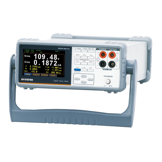
GETTING STARTED Appearance Front Panel CURRENT VOLTAGE GPM-8213 INTEGRATOR CAT II 300V POWER Power Switch POWER Turns On or Off the main power. - Page 18 The maximum measurable current and voltage are 600 V and 10A for voltage and current terminals of the front Warning panel of the GPM-8213. Do not input exceeded voltage and current, otherwise it will burn the device. Function keys...
- Page 19 GETTING STARTED Press this button to display the maximum measurement reading. See page 51. Press this key to select measure mode (DC/AC/AC+DC). See page Press this key to enter the measurement settings menu. See page 34. Press this key to switch window and stop refreshing.
- Page 20 GPM-8213 User Manual Cancel (Exit) Press this button to cancel the button current setting. The cursor returns to the default position or return to the previous menu according to the situation. See page 52. Arrow Keys This for arrow keys are used...
-
Page 21: Display Overview
GETTING STARTED Display Overview Voltage Range Mode Max. Hold Average Range Current Range Remote Filter KeyLock Display Hold Peak Voltage Peak Current Main Measurement Display Minor Measurement Display Remote Error Secondary Menus Status icon Description Item V_Range 300V Voltage measurement range. Voltage Range Example here range is 300V. - Page 22 GPM-8213 User Manual External current magnification CT Ratio State (on/off) Max. Hold Retain and display the maximum Maximum Hold measurement reading. KeyLock Lock Key button Keyboard Lock Avg-1 Average number of sampling Average (1/2/4/8/16/32/64) Hold Retain and display the current Display Hold measurement reading.
- Page 23 GETTING STARTED System This function key is used to enter the system setting and system configuration screens.
-
Page 24: Rear Panel
GPM-8213 User Manual Rear Panel CURRENT VOLTAGE WARNING CAT II 300V Power Cord Accepts the power cord. Socket AC 100~240V ±10%, 50/60Hz ... - Page 25 The maximum measurable current and voltage are 600 V and 20A for voltage and current terminals of the rear panel of the GPM-8213. Do not input exceeded voltage and current, otherwise it will burn the device. Always use the supplied cable for connection.
-
Page 26: Set Up
GPM-8213 User Manual Set Up Tilting the Stand From the base of the handle, gently pull the handle out sideways and then rotate it to one of the following positions. Horizontal position Tilt stand position Carry position 2 2 6... -
Page 27: Power Up
GETTING STARTED Power Up Steps 1. Ensure the AC voltage is 100~ 240V. 2. Connect the power cord to the AC voltage input. Make sure the ground connector on the power Note cord is connected to a safety ground. This will influence the measurement accuracy. -
Page 28: Connect The Wires To The Gpm-8213
GPM-8213 User Manual Connect the wires to the GPM-8213 Two separate wires is used to connect the Background GPM-8213, so voltage and current measurement are isolated and don’t interfere with each other. CURRENT VOLTAGE Connection diagram ... -
Page 29: Basic Setting
BASIC SETTING ASIC SETTING Setting up measurement range ......... 30 Auto Range ..............32 Setting up measurement status ........ 34 Setting up synchronization source ......34 Setting up filter ............35 Setting up crest factor ..........36 Setting up auto-zero function ........37 Setting up average value .......... -
Page 30: Setting Up Measurement Range
GPM-8213 User Manual Setting up measurement range To get the accurate measurement results, you should set an appropriate measurement range before you perform measurement task. Set voltage range 1. Press V-Range button. V - Range 2. Use up and down arrow keys to select the desired range. - Page 31 BASIC SETTING 2. Use up and down arrow keys to select the desired range. 3. Press Enter button to confirm your Enter selection. Available range Crest Factor AUTO, 5mA, 10mA, 20mA, 50mA, is 3: 100mA, 200mA, 0.5A, 1A, 2A, 5A,10A, Crest Factor AUTO, 2.5mA, 5mA, 10mA, 25mA, is 6:...
-
Page 32: Auto Range
GPM-8213 User Manual The P.V status icon lights in red when the voltage Note measurement circuit detects that the measured value exceeds setting range by 3 folds (CF is set to 3) or 6 folds (CF is set to 6). - Page 33 BASIC SETTING Example Irms exceeds the current setting range by 110%, so range is shifted to 20mA Irms is less than or equal to 60% of the previous setting range, so range is shifted down to 10mA.
-
Page 34: Setting Up Measurement Status
GPM-8213 User Manual Setting up measurement status Setting up synchronization source Setup 1. Press Setup button. Steps 2. Press Enter button. Enter 3. Press down arrow key. 4. Press Enter button to enter Sync Enter Source item. Use up and down... -
Page 35: Setting Up Filter
BASIC SETTING Setting up filter Setup 1. Press Setup button. Steps 2. Press Enter button. Enter 3. Press down arrow key twice. 4. Press Enter button to enter Filter Enter item. Use up and down arrow keys to select the desired option and then press Enter button again to Enter confirm your selection. -
Page 36: Setting Up Crest Factor
GPM-8213 User Manual Setting up crest factor Setup 1. Press Setup button. Steps 2. Press Enter button. Enter 3. Press down arrow key three times. 4. Press Enter button to enter Crest Enter Factor item. Use up and down arrow keys to select the desired... -
Page 37: Setting Up Auto-Zero Function
BASIC SETTING Setting up auto-zero function Setup 1. Press Setup button. Steps 2. Press Enter button. Enter 3. Press down arrow key four times. 4. Press Enter button to enter Auto Enter Zero item. Use up and down arrow keys to select the desired option and then press Enter button again Enter to confirm your selection. -
Page 38: Setting Up Average Value
GPM-8213 User Manual Setting up average value Setup 1. Press Setup button. Steps 2. Press Enter button. Enter 3. Press down arrow key five times. 4. Press Enter button to enter Average Enter item. Use up and down arrow keys... -
Page 39: Setting Up Method Of Calculating Harmonics
BASIC SETTING Setting up method of calculating harmonics Setup 1. Press Setup button. Steps 2. Press Enter button. Enter 3. Press down arrow key six times. 4. Press Enter button to enter Enter Harmonics item. Use up and down arrow keys to select the desired option and then press Enter button Enter again to confirm your selection. -
Page 40: Setting Up The Pt Ratio Status
GPM-8213 User Manual Setting up the PT ratio status Setup 1. Press Setup button. Steps 2. Press Enter button. Enter 3. Press down arrow key seven times. 4. Press Enter button to enter PT Enter Ratio Status item. Use up and... -
Page 41: Setting Up The Ct Ratio Status
BASIC SETTING Setting up the CT ratio status 1. Press Setup button. Steps 2. Press Enter button. Enter 3. Press down arrow key eight times. 4. Press Enter button to enter CT Enter Ratio Status item. Use up and down arrow keys to select the desired option and then press Enter Enter button again to confirm your... -
Page 42: Setting Up System Status
GPM-8213 User Manual Setting up System status System configuration setting screen 1. Use left and right arrow keys on Steps the front panel to select System function key. 2. Press Enter button to Enter Enter SYSTEM INFORMATION setting screen. 3. Press right arrow key to select Config key. -
Page 43: Setting Up Brightness
BASIC SETTING 2. Press Enter button to enter Power Enter On Status Setup item. Use up and down keys to select the desired option and then press Enter button Enter again to confirm your selection. Option Previous: The status of device on powering on is set to the status before the last shutdown. -
Page 44: Setting Up Key Sound
GPM-8213 User Manual 2. Press Enter button to enter Enter Brightness item. Use up and down keys to select a number and then press Enter button again to confirm Enter your selection. Option 1 to 9 The display is the darkest when set to 1. -
Page 45: Setting Up Interface
BASIC SETTING 2. Press Enter button to enter Key Enter Sound item. Use up and down arrow keys to select the desired option and then press Enter button Enter again to confirm your selection. Option A short sound is heard from the speaker of device when pressing the keys on the front panel. - Page 46 GPM-8213 User Manual 2. Press Enter button to enter I/O Enter Model item. Use up and down arrow keys to select the desired option and then press Enter button Enter again to confirm your selection. Option RS232: If interface is set to RS232, the Baud Rate can be selected from the following options.
-
Page 47: Measurement And Other Functions
MEASUREMENT AND OTHER FUNCTIONS EASUREMENT AND OTHER FUNCTIONS Measurement function ..........48 Introduction to measurement parameters ....48 Setting measurement parameters ......49 Other functions ............51 Introduction to other functions ......... 51 Integration measurement function ......53 Setting up Integrator measurement ......53 Introduction to integrator parameters ...... -
Page 48: Measurement Function
GPM-8213 User Manual Measurement function The GPM-8213 provides a wide range of basic electricity and power measurement functions. It equips with different accurate measurement parameters for accurately measuring the voltage, current, power, DC/AC/AC + DC, power factor, harmonics, frequency, etc. The input impedance of the device is 2.4MΩ, the maximum input voltage is 600Vrms. -
Page 49: Setting Measurement Parameters
MEASUREMENT AND OTHER FUNCTIONS P+pk and P-pk Active Power Peak THDI and THDV Total Harmonic Distortion CFV, CFI Crest factor Setting measurement parameters Please follow the steps blow to set the measurement parameters 1. Use left and right arrow keys on Steps the front panel to select Parameter function key. - Page 50 GPM-8213 User Manual 5. In standard display mode, you Enter Switching display simply press the Enter button to mode switch display mode to simple one. 6. Press ESC button to return back to original display mode.
-
Page 51: Other Functions
MEASUREMENT AND OTHER FUNCTIONS Other functions Introduction to other functions Mode Max. Hold KeyLock Display Hold Function name Button Description MAX Hold When the MAX Hold button is MAX Hold pressed, the MAX Hold status icon will light in red in the LCD display to indicate that this function is activated. - Page 52 GPM-8213 User Manual Mode Press this button to select Mode measurement mode. There are 3 measurement modes. AC+DC: Displays all the components of the measurement signal DC: Displays the DC part of the measurement signal. AC: Displays the AC part of the ...
-
Page 53: Integration Measurement Function
MEASUREMENT AND OTHER FUNCTIONS Integration measurement function Setting up Integrator measurement 1. Use left and right arrow keys on steps the front panel to select Integrator function key. 2. Press Enter button to enter the Enter integrator measurement screen. 3. Press right arrow key to select Set key. - Page 54 GPM-8213 User Manual 4. Press Enter button to enter Enter Select integrator integrator measurement setting measurement mode screen. 5. Press Enter button to enter Mode Enter item. Use up and down arrow keys to toggle between Manual and Standard mode. Press Enter button Enter again to confirm your selection.
- Page 55 MEASUREMENT AND OTHER FUNCTIONS If you select standard mode, you need to set integrator measurement time before using integrator function. It can be set from 1 second to 9999 hours, 59 minutes and 59 seconds. 6. Press down arrow key to select Function item in the integrator measurement setting screen.
-
Page 56: Introduction To Integrator Parameters
GPM-8213 User Manual Introduction to integrator parameters Parameter name Description Manual Mode Standard Watt Hours Function WP: Total power WP+: Positive total power WP-: Negative total power Ampere Hours q: Total mAh q+: Positive total... - Page 57 MEASUREMENT AND OTHER FUNCTIONS Running State Integrator measurement is in progress. Stop Integrator measurement has been stopped manually. Timeout The time for running integrator measurement is up. Reset The integrator measurement status is cleared. ...
-
Page 58: Using The Integrator Function
GPM-8213 User Manual Using the integrator function 1. In manual mode, you can directly Manual mode Start press the Start button in the front panel to start integrator function. Stop 2. To stop integration function, press the Stop button in the front panel. - Page 59 1. Set integrator measurement time before using Standard mode integrator function. 2. Other steps are same as running in manual mode. When integrator performing, the test time will increase until the setting integrator measurement time. In the integration process, select the Measure ...
-
Page 60: Remote Control
REMOTE CONTROL EMOTE CONTROL This chapter describes basic configuration of IEEE488.2 based remote control. For a command list, refer to the Command Overview chapter on page 65. Configure Remote Control Interface ......61 USB Interface ............. 61 Configure USB Interface ..........61 Configure RS232 Interface ......... -
Page 61: Configure Remote Control Interface
The USB device port on the rear panel is used for remote control. The USB port is configured as CDC interface. When configured to CDC, the USB port on the GPM-8213 will appear as a virtual COM port to a connected PC. Any terminal program that can communicate via a serial port can be used for remote control. - Page 62 GPM-8213 User Manual RS232 Pin Pin 2: RxD 1 2 3 4 5 Assignments Pin 3: TxD Pin 5: GND Pin 1, 4, 6 ~ 9: No 6 7 8 9 Connection Use a Null Modem connection as shown in the PC Connection diagram below.
- Page 63 REMOTE CONTROL 3. Select a desired IP Model. Option Manual Set up IP Address, Subnet mask and Gateway manually. DHCP For details about configuring USB interface, please see page 61.
-
Page 64: Return To Local Control
GPM-8213 User Manual Return to Local Control When the unit is in remote control mode, the Background RMT icon above the main display can be seen. When this icon is not displayed, it indicates that the unit is in local control mode. -
Page 65: Command Overview
COMMAND OVERVIEW OMMAND OVERVIEW The Command overview chapter lists all programming commands in functional order as well as alphabetical order. The command syntax section shows you the basic syntax rules you have to apply when using commands. Command Syntax Partial compatibility Compatible IEEE488.2 Standard... - Page 66 GPM-8213 User Manual There are a number of different instrument Command Types commands and queries. A command sends instructions or data to the unit and a query receives data or status information from the unit. Command types A single command...
- Page 67 COMMAND OVERVIEW Commands that contain square brackets Square Brackets indicate that the contents are optional. The function of the command is the same with or without the square bracketed items, as shown below. For example, for the query: [:INPut]:FILTer? Both :INPut:FILTer? and :FILTer? are valid forms. Command :INPut:VOLTage:RANGe Format...
- Page 68 GPM-8213 User Manual For commands, this will set the [MAX] (Optional setting to the highest value. This parameter) parameter can be used in place of any numerical parameter where indicated. For queries, it will return the highest possible value allowed for the particular setting.
-
Page 69: Command List
COMMAND OVERVIEW Command List SCPI Commands *CLS ..................71 *IDN ..................71 *ESE ..................71 *ESR ..................72 *OPC ..................72 *RST ..................72 *SRE ..................73 *STB ..................73 :COMMunicate:HEADer ............74 COMMunciate :COMMunicate:REMote ............74 Commands :COMMunicate:VERBose ............. 75 :DISPlay[:NORMal]:ITEM<x>... - Page 70 GPM-8213 User Manual :INTegrate:MODE ..............87 INTEgrate :INTegrate:FUNCtion ............87 commands :INTegrate:TIMer..............88 :INTegrate:STARt ..............88 :INTegrate:STOP ..............88 :INTegrate:RESet ..............88 :INTegrate:STATe ..............89 :MEASure:AVERaging:COUNt ........... 90 MEASure :MEASure:MHOLd ..............90 commands :NUMeric[:NORMal]:VALue? ..........91 NUMeric :NUMeric[:NORMal]:NUMBer..........92 commands :NUMeric[:NORMal]:ITEM<x>...
-
Page 71: Scpi Commands *Cls
Returns the manufacturer, model number, serial Description number, and system version of the instrument. Query Syntax *IDN? Return parameter <String> Example *IDN? ->GWINSTEK,GPM-8213, GXXXXXXXX,V1.00 *ESE Query Sets or returns the ESER (Event Status Enable Description Register) contents. Syntax *ESE <NR1>... -
Page 72: Esr
GPM-8213 User Manual Parameter/ 0~255 <NR1> Return parameter Example *ESE 65 Set the ESER to 01000001 *ESE? ->130 ESER=10000010 *ESR Query Returns SESR (Standard Event Status Register). Description Query Syntax *ESR? Return parameter <NR1> 0~255 Example *ESR? ->198 SESR=11000110 *OPC... -
Page 73: Sre
COMMAND OVERVIEW *SRE Query Sets or returns SRER (Service Request Enable Description Register) Syntax *SRE <NR1> Query Syntax *SRE? Parameter/ 0~255 <NR1> Return parameter Example *SER 7 Set the the SRER to 00000111 *SRE? ->3 SRER=00000011 *STB Query Returns the SBR (Status Byte Register) contents. Description Query Syntax *STB? -
Page 74: Communciate :Communicate:header
Example of a response with a header :INPUT:VOLTAGE:RANGE 150.0E+00 Example of a response without a header 150.0E+00 :COMMunicate:REMote Query Sets or returns the GPM-8213 series to remote or Description local mode. ON is remote mode. Syntax :COMMunicate:REMote <Boolean>|{OFF | ON}... -
Page 75: Communicate:verbose
COMMAND OVERVIEW Parameter <Boolean>0 OFF <Boolean>1 ON Return parameter 0 Turn the remote function off Turn the remote function on Example :COMMUNICATE:REMOTE ON :COMMUNICATE:REMOTE? ->:COMMUNICATE:REMOTE 1 :COMMunicate:VERBose Query Sets or returns whether the response to a query is Description returned fully spelled out or in its abbreviated form. -
Page 76: Display :Display[:Normal]:Item
GPM-8213 User Manual DISPlay Commands :DISPlay[:NORMal]:ITEM<x> ........... 76 :DISPlay:INTegrate:ITEM<x> ..........77 :DISPlay:PAGE ............... 78 :DISPlay[:NORMal]:ITEM<x> Query Sets or returns a normal measurement data display Description item. Syntax :DISPlay[:NORMal]:ITEM<x> <Function> Query Syntax :DISPlay[:NORMal]:ITEM<x>? Parameter/ <x> 1 to 8 (display) Return parameter <Function>... -
Page 77: Commands :Display:integrate:item
1 to 2(display) Return parameter <Function> {WHP|WHM|AHP|AHM|U|I }. Example :DISPLAY:INTEGRATE:ITEM1 WHP :DISPLAY:INTEGRATE:ITEM1? ->:DISPLAY:INTEGRATE:ITEM1 WHP <Function> Function GPM-8213 Indicator Positive watt hour WP+ [WP+] Positive watt hour WP- [WP-] Positive ampere hour q+ [q+] Positive ampere hour q [q-] Voltage U... -
Page 78: Display:page
GPM-8213 User Manual :DISPlay:PAGE Query Sets or returns the display page item. Description Syntax :DISPlay:PAGE <Function> Query Syntax :DISPlay:PAGE? Parameter/ <Function> {MEASurement|ENLArge|INTEgral| SYSTem_INFO|SYSTem_CONFig|SETUp} Return parameter Example :DISPLAY:PAGE MEASUREMENT :DISPLAY:PAGE? ->:DISPLAY:PAGE MEASUREMENT... -
Page 79: Harmonics :Harmonics:thd
COMMAND OVERVIEW HARMonics Command :HARMonics:THD Query Sets or returns the equation used to compute the Description THD (total harmonic distortion). Syntax :HARMonics:THD {TOTal|FUNDamental} Query Syntax :HARMonics:THD? Parameter/ TOTal (CSA) FUNDamental (IEC) Return parameter Example :HARMONICS:THD FUNDAMENTAL :HARMONICS:THD? ->:HARMONICS:THD FUNDAMENTAL... -
Page 80: Hold Command :Hold
GPM-8213 User Manual HOLD Command :HOLD Query Sets or returns the on/off state of the output hold Description feature for display, communication, and other types of data. Syntax :HOLD <Boolean>|{OFF|ON} Query Syntax :HOLD? Parameter <Boolean>0 <Boolean>1 Return parameter 0 Turn the hold function off... -
Page 81: Input [:Input]:Cfactor
COMMAND OVERVIEW INPut Commands [:INPut]:CFACtor ..............81 [:INPut]:MODE ..............81 [:INPut]:VOLTage:RANGe ..........82 [:INPut]:VOLTage:AUTO ............ 82 [:INPut]:CURRent:RANGe ..........83 [:INPut]:CURRent:AUTO ............ 83 [:INPut]:SCALing:{VT/PT|CT}:STATe ......84 [:INPut]:SCALing:{VT/PT|CT}:RATio ......84 [:INPut]:SYNChronize ............84 [:INPut]:FILTer ............... 85 [:INPut]:ZERO ............... 85 [:INPut]:CFACtor Query Sets or returns the crest factor. Description Syntax [:INPut]:CFACtor {<NRf>}... -
Page 82: [:Input]:Voltage:range
GPM-8213 User Manual Parameter/ Select the dc measurement mode. Return parameter Select the acdc measurement mode. Select the ac mode. Example :INPUT:MODE DC :INPUT:MODE? ->:INPUT:MODE DC [:INPut]:VOLTage:RANGe Query Sets or returns the voltage range. Description Syntax [:INPut]:VOLTage:RANGe {<Voltage>} Query Syntax... -
Page 83: [:Input]:Current:range
COMMAND OVERVIEW Example :INPUT:VOLTAGE:AUTO ON :INPUT:VOLTAGE:AUTO? ->:INPUT:VOLTAGE:AUTO 1 [:INPut]:CURRent:RANGe Query Sets or returns the current range. Description Query [:INPut]:CURRent:RANGe {<Current>} Query Syntax [:INPut]:CURRent:RANGe? Parameter/ <Current> 5, 10, 20, 50, 100, 200, 500(mA) Return parameter 1, 2, 5, 10, 20(A) when the crest factor is set to 3. -
Page 84: [:Input]:Scaling:{Vt/Pt|Ct}:State
GPM-8213 User Manual [:INPut]:SCALing:{VT/PT|CT}:STATe Query Sets or returns the scaling vt/pt,ct on/off state. Description Syntax [:INPut]:SCALing:{VT/PT|CT}:STATe {<Boolean>} Query Syntax [:INPut]:SCALing:{VT/PT|CT}:STATe? Parameter <Boolean>0 OFF <Boolean>1 ON Return parameter 0 Turn the scaling vt/pt, ct function off. Turn the scaling vt/pt, ct function on. -
Page 85: [:Input]:Filter
COMMAND OVERVIEW Parameter/ Select the voltage synchronization source. Return parameter Select the current synchronization source. Select the off synchronization source. Example :INPUT:SYNCHRONIZE VOLTAGE :INPUT:SYNCHRONIZE? ->:INPUT:SYNCHRONIZE VOLTAGE [:INPut]:FILTer Query Sets or returns the filter state. Description Syntax [:INPut]:FILTer {<Boolean>} Query Syntax [:INPut]:FILTer? Parameter <Boolean>0 OFF... - Page 86 GPM-8213 User Manual Example :INPUT:ZERO OFF :INPUT:ZERO? ->:INPUT:ZERO 0...
-
Page 87: Integrate :Integrate:mode
COMMAND OVERVIEW INTegrate Commands :INTegrate:MODE ..............87 :INTegrate:FUNCtion ............87 :INTegrate:TIMer ..............88 :INTegrate:STARt ..............88 :INTegrate:STOP ..............88 :INTegrate:RESet ..............88 :INTegrate:STATe ..............89 :INTegrate:MODE Query Sets or returns the integration mode. Description Syntax :INTegrate:MODE {MANUal | STANdard} Query Syntax :INTegrate:MODE? Parameter/ MANUal... -
Page 88: Integrate:timer
GPM-8213 User Manual :INTegrate:TIMer Query Sets or returns the integration timer value. Description Syntax :INTEGrate:TIMer {<NRf>,<NRf>,<NRf>} Query Syntax :INTEGrate:TIMer? Parameter/ {<NRf>,<NRf>,<NRf>} 0,0,0 to 9999,59,59 Return parameter First <NRf> 0 to 9999 (hours) Second <NRf> 0 to 59 (minutes) Third <NRf>... -
Page 89: Integrate:state
COMMAND OVERVIEW :INTegrate:STATe Query Queries the integration status. Description Syntax :INTegrate:STATe? Example :INTEGRATE:STATE? ->RESET Response Overflow Integration overflows. RESET Integration resets. RUNNING Integration is in progress. STOP Integration stops. TIMEUP Integration stops due to integration timeout. -
Page 90: Measure Commands
GPM-8213 User Manual MEASure Commands :MEASure:AVERaging:COUNt ........... 90 :MEASure:MHOLd ..............90 :MEASure:AVERaging:COUNt Query Sets or returns the averaging coefficient. Description Syntax :MEASure:AVERaging:COUNt {<NRf>} Query Syntax :MEASure:AVERaging:COUNt? Parameter/ <NRf> 1, 2, 4, 8, 16, 32, 64 Return parameter Example :MEASURE:AVERAGING:COUNT 8 :MEASURE:AVERAGING:COUNT? ->:MEASURE:AVERAGING:COUNT 8... -
Page 91: Numeric :Numeric[:Normal]:Value
COMMAND OVERVIEW NUMeric Commands :NUMeric[:NORMal]:VALue?..........91 :NUMeric[:NORMal]:NUMBer ........... 92 :NUMeric[:NORMal]:ITEM<x> ......... 92 :NUMeric[:NORMal]:PRESet ..........94 :NUMeric[:NORMal]:CLEar ..........96 :NUMeric[:NORMal]:DELete ..........97 :INTegrate:STATe ..............97 :NUMeric[:NORMal]:VALue? Query Returns the numeric data. Description Syntax :NUMeric[:NORMal]:VALue? Example :NUMERIC:NORMAL:VALUE? -> 103.79E+00,1.0143E+00,105.27E+00,..(omitted)..,50.0 01E+00 Measurement values U, I, P, PPPeak, PMPeak, S, Numeric Data Format Q, LAMBda, CFU, CFI, FU, FI, UTHD and ITHD... -
Page 92: Commands :Numeric[:Normal]:Number
GPM-8213 User Manual No items (“-----”) ASCII: NAN (Not A Number) Data does not exist (the display shows “-----”) Error Data ASCII: NAN (Not A Number) :NUMeric[:NORMal]:NUMBer Query Sets or returns the specified numeric data output Description item function. - Page 93 Return parameter <Function> {U|UPPeak|UMPeak|I|IPPeak|IMPeak |P|PPPeak|PMPeak|S|Q|LAMBda|CFU |CFI|PHI|FU|FI|UTHD|ITHD|WH |WHP|WHM|AH|AHP|AHM|TIME |URANge|IRANge} Example :NUMERIC:NORMAL:ITEM1 U :NUMERIC:NORMAL:ITEM1? ->:NUMERIC:NORMAL:ITEM1 U <Function> Function GPM-8213 Indicator Voltage U UPPeak Maximum voltage: U+pk [V+pk] UMPeak Minimum voltage: U-pk [V-pk] Current I IPPeak Maximum current: I+pk [I+pk] IMPeak Minimum current: I-pk...
-
Page 94: Numeric[:Normal]:Preset
GPM-8213 User Manual ITHD Total harmonic distortion of [THDI] current Ithd Watt hour WP [WP] Positive watt hour WP+ [WP+] Positive watt hour WP- [WP-] Ampere hour q Positive ampere hour q+ [q+] Positive ampere hour q [q-] TIME Integration time... - Page 95 COMMAND OVERVIEW Patterns 3 ITEM<x> <Function> LAMBda UPPeak UMPeak IPPeak IMPeak PPPeak PMPeak Patterns 4 ITEM<x> <Function> LAMBda...
-
Page 96: Numeric[:Normal]:Clear
GPM-8213 User Manual UPPeak UMPeak IPPeak IMPeak TIME PPPeaK PMPeaK UTHD ITHD URANge IRANge :NUMeric[:NORMal]:CLEar Clears numeric data output items (sets the items to Description “-----“). Syntax :NUMeric[:NORMal]:CLEar {ALL|<NRf>[,<NRf>]} Parameter First <NRf> 1 to 34 (the number of the first item to clear) Second <NRf>... -
Page 97: Numeric[:Normal]:Delete
COMMAND OVERVIEW Note If the 2nd <NRf> is omitted, the output item specified by the first and all following output items (up to number 34) are cleared. :NUMeric[:NORMal]:DELete Deletes numeric data output items. Description Syntax :INTegrate:RESet Parameter First <NRf> 1 to 34 (the number of the first item to delete) Second <NRf>... -
Page 98: System :System:model
GPM-8213 User Manual SYSTem Commands :SYSTem:MODel?..............98 :SYSTem:MODel?..............98 :SYSTem:VERSion? ............... 98 :SYSTem:KLOCk ..............99 :SYSTem:BRIGhtness ............99 :SYSTem:KEY:BEEPer ............100 :SYSTem:MODel? Query Returns the model code. Description Syntax :SYSTem:MODel? Example :SYSTEM:MODEL? ->:SYSTEM:MODEL "GPM-8213" :SYSTem:MODel? Query Returns the serial number. -
Page 99: System:klock
COMMAND OVERVIEW Note Returns the Ver. item string of the system Information menu. :SYSTem:KLOCk Query Sets or returns the on/off state of the key Description protection. Syntax :SYSTem:KLOCk {<Boolean>} Query Syntax :SYSTem:KLOCk? Parameter <Boolean> 0 <Boolean> 1 Return parameter 0 Turn the key protection function off Turn the key protection function on. -
Page 100: System:key:beeper
GPM-8213 User Manual :SYSTem:KEY:BEEPer Query Sets or returns the keyclick beeper state. Description Syntax :SYSTem:KEY:BEEPer {<Boolean>} Query Syntax :SYSTem:COMMunicate:LAN:CONFigure? Parameter <Boolean> 0 <Boolean> 1 Return parameter 0 Turn the keyclick beeper function off. Turn the keyclick beeper function on. Example... - Page 101 COMMAND OVERVIEW STATus Command :STATus:ERRor? Query Queries the error code and message of the last Description error that has occurred (top of the error queue). Query Syntax :STATus:ERRor? Example :STATUS:ERROR? -> Error_103:Invalid separator If no errors have occurred, 0,”No error” is Note returned.
-
Page 102: Appendix
APPENDIX PPENDIX Specifications ............103 General Specifications ............103 Input .................. 104 Display ................104 Voltage Measurement ............105 Current Measurement ............105 Power Measurement ............106 Frequency Measurement ..........106 Integrator Measurement ........... 106 Dimensions ............107 Declaration of Conformity ........108 Power measurement .......... -
Page 103: Specifications
APPENDIX Specifications Below are the basic conditions required to operate the GPM-8213 within specification: Calibration: Yearly 18~28 ˚C (64.4~82.4˚F) Operating Environment: Humidity: <80%RH, Accuracy: ± (% of reading + % of range) The specifications apply when it warmed up for at least 30 ... -
Page 104: Input
GPM-8213 User Manual Input Item Spec. Input voltage 600 Vrms Input current 20 Arms Voltage 2.4MΩ Input 5mA - 200mA 500mΩ impedance(50/60 Hz) Current 0.5A - 20A 5mΩ Maximum display voltage 700 Vrms Maximum display current 25 Arms Maximum allowable isolation voltage... -
Page 105: Voltage Measurement
APPENDIX Voltage Measurement CF=3 : 15V, 30V, 60V, 150V, 300V, 600V Measurement range CF=6 : 7.5V, 15V, 30V, 75V, 150V, 300V Crest factor 3, 6 Effective range 1 % to 105 % of range ±(0.2 % reading + 0.2 % range) 45 Hz ≤f ≤... -
Page 106: Power Measurement
GPM-8213 User Manual Power Measurement Effective range 1 % to 110 % of range ±(0.2 % reading + 0.2 % range) 45 Hz ≤f ≤ 66 Hz ±(0.1 % reading + 0.1 % range) Accuracy 66 Hz < f ≤ 1kHz ±(0.1 % reading + 0.3 % range) -
Page 107: Dimensions
APPENDIX Dimensions Units = mm... -
Page 108: Declaration Of Conformity
GPM-8213 User Manual Declaration of Conformity GOOD WILL INSTRUMENT CO., LTD. declare that the below mentioned product Type of Product: Digital Power Meter Model Number: GPM-8213 are herewith confirmed to comply with the requirements set out in the Council Directive on the Approximation of the Law of Member States relating to EMC (2014/30/EU), LVD (2014/35/EU), WEEE (2012/19/EU) and RoHS (2011/65/EU). -
Page 109: Power Measurement
APPENDIX Power measurement Direct read method: Directly read the Method measurement value measured from power measuring instrument. The average power method: Record the actual power value within a settable period of time and then take the average. A settable period of time isn’t less than 10min. -
Page 110: Measurement For Large Current
GPM-8213 User Manual Measurement for large current Voltage measurement mode measured from load side (Connect to ammeter externally). The voltage measurement is accurate. The current measurement on load could be larger than the actual one due to leakage current of multi-measurement voltage. -
Page 111: Introduction To Iec-62301
The active power includes AC and DC components. Over-range automatic alarm function is available. Turning off the auto range function is available. Harmonic bandwidth is greater than or equal to 2.5kHz. The GPM-8213 meets all of the features listed above. -
Page 112: Eup Directive Lot6 Specifications
GPM-8213 User Manual EUP Directive Lot6 specifications Ecodesign directive for energy-using products: The power loss requirement for the products with external power supply such as information devices, consumer electronics product, household appliances, toys, entertainment and sports products and so on in standby and off mode is as below. -
Page 113: Connection Guide
APPENDIX Connection Guide Front panel Lower current measurement: I < 1A SOURCE LOAD Method 1 CURRENT VOLTAGE SOURCE LOAD AC 10A AC 600V CAT II 300V SOURCE LOAD Method 2 CURRENT VOLTAGE SOURCE LOAD AC 10A AC 600V CAT II 300V Higher current measurement: 1A <... -
Page 114: Rear Panel
GPM-8213 User Manual SOURCE LOAD Method 2 CURRENT VOLTAGE SOURCE LOAD AC 10A AC 600V CAT II 300V Rear panel Direct connection: 10A < I < 20A SOURCE LOAD CURRENT VOLTAGE SOURCE LOAD 600V CAT II 300V Connection with CT/PT...
Need help?
Do you have a question about the GPM-8213 and is the answer not in the manual?
Questions and answers