
Related Manuals for Waters Alliance e2695


Summary of Contents for Waters Alliance e2695
- Page 1 View More Resources at www.Chromatography.co Waters Alliance e2695 Separations Module Operator’s Guide 715003794/Revision B Copyright © Waters Corporation 2013 All rights reserved...
- Page 2 July 29, 2013, 715003794 Rev. B...
-
Page 3: General Information
Corporation assumes no responsibility for any errors that may appear in this document. This document is believed to be complete and accurate at the time of publication. In no event shall Waters Corporation be liable for incidental or consequential damages in connection with, or arising from, its use. For the most recent revision of this document, consult the Waters Web site (waters.com). -
Page 4: Contacting Waters
Contacting Waters ® Contact Waters with enhancement requests or technical questions regarding the use, transportation, removal, or disposal of any Waters product. You can reach us via the Internet, telephone, or conventional mail. Waters contact information: Contacting medium Information... -
Page 5: Considerations Specific To The Waters Alliance E2695 Separations Module
Considerations specific to the Waters Alliance e2695 Separations Module Solvent leakage hazard The source exhaust system is designed to be robust and leak-tight. Waters recommends you perform a hazard analysis, assuming a maximum leak into the laboratory atmosphere of 10% LC eluate. -
Page 6: Canada Spectrum Management Emissions Notice
Hand crush hazard To avoid hazards associated with the reciprocating or rotating Warning: parts in the source, keep clear of the regions marked with yellow and gray labels. High temperature hazard To avoid burn injuries, avoid touching the source enclosure Warning: when operating or servicing the instrument. -
Page 7: Equipment Misuse Notice
Equipment misuse notice If the equipment is used in a manner not specified by the manufacturer, the protection provided by the equipment may be impaired. Safety advisories Consult Appendix A for a comprehensive list of warning and caution advisories. Operating this instrument When operating this instrument, follow standard quality-control (QC) procedures and the guidelines presented in this section. -
Page 8: Applicable Symbols
This guide is intended for use by individuals who need to install, operate, maintain, or troubleshoot the Waters Alliance e2695 Separations Module. This guide sets forth procedures for unpacking, installing, using, maintaining, and troubleshooting the Waters Alliance e2695 Separations Module. It also includes appendixes for specifications, spare parts, and solvent considerations. -
Page 9: Intended Use Of The Waters Alliance E2695 Separations Module
Waters designed the Alliance e2695 Separations Module, an integrated solvent and sample management platform, to facilitate all critical separations functions. The Waters Alliance e2695 Separations Module is for research use only and is not intended for use in diagnostic applications. -
Page 10: Ec Authorized Representative
EC authorized representative Waters Corporation (Micromass UK Ltd.) Floats Road Wythenshawe Manchester M23 9LZ United Kingdom Telephone: +44-161-946-2400 Fax: +44-161-946-2480 Contact: Quality manager July 29, 2013, 715003794 Rev. B... -
Page 11: Table Of Contents
Customer comments .................... iii Contacting Waters ....................iv Safety considerations ..................iv Considerations specific to the Waters Alliance e2695 Separations Module ..v FCC radiation emissions notice ................. vi Canada spectrum management emissions notice ..........vi Electrical power safety notice ................vi Safety hazard symbol notice................ - Page 12 Spill protection ....................26 Record-keeping functions .................. 26 Power supply ...................... 27 Solvent management system overview ............27 Solvent blending ....................28 Prime/vent valve ....................28 Plunger seal-wash system ................. 28 Loss of prime protection ..................29 Preferred plunger stroke volume ..............29 In-line vacuum degasser..................
- Page 13 2 Install the e2695 Separations Module ..........45 Installation overview ..................45 Site requirements ....................46 Firmware and software requirements ............47 Unpack ........................48 Connect to the electrical power supply ............48 Connect tubing and attachments ..............50 Install B-series detector base and drip tray ............. 50 Install A and C series drip tray and support bracket ........
- Page 14 Enter values in parameter fields ..............88 Configure the separations module ..............91 Set configuration parameters................91 Configure the operating mode................98 Prepare the solvent management system ..........103 Prepare solvent reservoirs................104 Degassing solvents................... 105 Prime the plunger seal-wash pump ..............106 Prime the solvent management system............
- Page 15 Monitor your HPLC system ................119 Perform direct functions ................123 Dry prime the system ..................126 Run System Prep ..................... 128 Wet prime the system..................129 Purge the 2410 and 410 reference cell............132 Equilibrate the system ..................132 Condition the column..................
- Page 16 Set separation method parameters ............. 150 Set Mobile Phase screen parameter values............ 151 Set sample parameter values ................157 Set autosampler parameter values ..............159 Set column parameter values................161 Set I/O parameter values ................162 Set detector parameters .................. 166 Create and edit a sample set .................
- Page 17 Create a GPV Test Method ................242 Verify the firmware checksum ................ 243 Troubleshoot ..................... 243 General troubleshooting hints ................ 243 When to call Waters Technical Service ............245 Troubleshoot chromatography problems ............245 Troubleshooting hardware problems ............. 252 A Safety Advisories .................. 261 Warning symbols ....................
- Page 18 Caution advisory ....................265 Warnings that apply to all Waters instruments and devices ....266 Warnings that address the replacing of fuses ........... 271 Electrical and handling symbols ..............273 Electrical symbols .................... 273 Handling symbols .................... 274 B Specifications ..................275 Physical specifications ...................
- Page 19 GPC solvents and seal choices ................ 293 Solvent compatibility ..................294 Solvents to avoid ....................295 Solvents to use ....................295 Solvent miscibility ................... 297 How to use miscibility numbers (M-numbers) ..........299 Buffered solvents ..................... 300 Head height ....................... 300 Solvent viscosity ....................
- Page 20 July 29, 2013, 715003794 Rev. B...
-
Page 21: Getting Started With The Alliance E2695 Separations Module
Operating configurations..............34 Options and accessories ..............39 Separations module overview The Alliance e2695 Separations Module is an integrated solvent and sample management platform. Integrating the two, traditional high performance liquid chromatography (HPLC) components—a solvent management system and a sample management system—facilitates all critical separations functions. -
Page 22: Hplc System Configurations
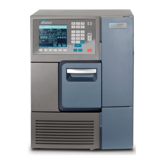
1 Getting started with the Alliance e2695 Separations Module Alliance e2695 Separations Module (front view): Front panel display and Syringe keypad access door Sample compartment access door Solvent Solvent conditioning delivery tray tray access access door door TP03527 HPLC system configurations The separations module supports RS-232, IEEE-488, Ethernet, and I/O connections for compatibility with a variety of HPLC system configurations. -
Page 23: Solvent Bottle Tray Kits
As a component of an HPLC system controlled by Empower software and that uses Ethernet communications • As a component of an HPLC system controlled by a non-Waters data system that uses RS-232 communications Solvent bottle tray kits There are several solvent bottle tray kits available for use with Alliance HPLC system configurations. - Page 24 1 Getting started with the Alliance e2695 Separations Module A-series solvent bottle organizer configuration: Solvent bottle organizer Drip tray Detector e2695 separations module July 29, 2013, 715003794 Rev. B...
-
Page 25: Control Of Chromatographic Functions
Separations module overview B-series solvent bottle tray configuration (only single detector shown): Detector Solvent bottle tray Drip tray and base Column heater or e2695 separations column heater/cooler module C-series solvent bottle bucket configuration: Detector Solvent bottle bucket e2695 separations Column heater or module column heater/cooler Control of chromatographic functions... -
Page 26: Spill Protection
1 Getting started with the Alliance e2695 Separations Module • Solvent composition • Flow rate • Plunger seal wash flow • Needle-wash flow • Sample injection • In-line vacuum degassing • External events • Operation of detectors over the IEEE-488 interface bus •... -
Page 27: Power Supply
Solvent management system overview Power supply The separations module is factory equipped with a 600 watt (W) power supply. This power supply provides immediate compatibility for an optional sample heater/cooler. The power supply is protected against short circuits. It does not use external replacement fuses, and is instead reset by powering-off the instrument and then powering it back on. -
Page 28: Solvent Blending
1 Getting started with the Alliance e2695 Separations Module Just before the accumulator chamber empties, the solvent in the primary piston chamber is precompressed to a pressure slightly less than that indicated by the system pressure transducer. When the accumulator piston chamber is empty, the primary piston delivers solvent, under pressure, through the primary pressure transducer. -
Page 29: Loss Of Prime Protection
Solvent management system overview • Plunger seal wash solvent flows from a reservoir to the solenoid wash pump and then to a cavity behind the main plunger seal in the primary head. • The solvent flows from the head and into the cavity behind the plunger seal, in the accumulator head. - Page 30 1 Getting started with the Alliance e2695 Separations Module low-internal-volume degasser chambers. The result is shortened instrument priming and equilibration times, and minimum delay when resuming operation from an idle state or following a solvent change. The degasser’s vacuum pump is designed specially for membrane degassing of HPLC mobile phases.
-
Page 31: Sample Management System Overview
Sample management system overview Sample management system overview The sample management system holds and positions the sample vials and injects the samples into the solvent flow. The system’s five carousels hold as many as 24 sample vials for a total of 120 vials. The vials are industry-standard, 2-mL vials with snap-on, crimp-on, or screw-on caps. -
Page 32: Normal Flow
1 Getting started with the Alliance e2695 Separations Module Normal flow During normal flow, V1 is open, allowing solvent to flow along two paths: • 95 percent of the solvent flows through the body of V2, the sample loop pressure transducer, the sample loop, and needle. The needle is in the Stream position, and solvent flows out the needle port, through the seal pack, and out to the column. -
Page 33: Vial Presence
Sample management system overview Spills and condensation in the sample compartment are routed to a waste connection below the front panel. You can load a carousel into the carrier while an injection is underway. An open-door sensor prevents the carrier from automatically advancing while you load the carousel (see “Load carousels”... -
Page 34: Operating Configurations
1 Getting started with the Alliance e2695 Separations Module Syringe assembly: Syringe TP03540 Operating configurations The separations module can operate in three general control modes: • System Controller • No Interaction • Remote Control Both System Controller and No Interaction are standalone modes. -
Page 35: System Controller Mode
Depending on your system components, you can connect the separations module to other components via these: • IEEE-488 (digital) signal connections for Waters detectors • I/O (analog) signal connections (hard wire cables) •... - Page 36 1 Getting started with the Alliance e2695 Separations Module Digital signal control of an HPLC system: IEEE-488 RS-232 connector cable e2695 Separations Printer Module IEEE-488 connector Waters 2487 Waters dual wavelength 2414/2410 RI UV detector detector In the System Controller mode, the separations module can control as many as three detector channels on the IEEE-488 bus (two UV detector channels and one RI detector channel).
-
Page 37: No Interaction Mode
In remote control mode, the separations module and the other HPLC system components are controlled by one of these data systems: • Empower Chromatography Data Software • Waters MassLynx Mass Spectrometry Software for mass spectrometers July 29, 2013, 715003794 Rev. B... - Page 38 Where the data system and separations module communicate via IEEE-488, and include one or more detectors that can only communicate with the data system via Ethernet (that is, a Waters 2998, 2489, 2475, 2424, e-SAT/IN module-connected, or Mass Spectrometer (for example,...
-
Page 39: Options And Accessories
Operate Gradient by Event In control In Operate Gradient by Event In mode, the separations module is connected to an external autosampler (a Waters 2700 Sample Manager, for example). In this mode, the separations module provides gradient functionality, and the external autosampler provides the sampling/injection functionality. -
Page 40: Column Heater
4 °C to 65 °C, with a set point temperature range that is ambient minus 15 °C or 4 °C (whichever is greater) to 65 °C, in 1 °C increments. The Waters Alliance Series Column Heater and Column Heater/Cooler Operator’s Guide presents the procedures for installing, operating, maintaining, and basic troubleshooting of the Alliance ®... -
Page 41: Column Selection Valve
Options and accessories Column selection valve The motorized column selection valve enables the system to switch solvent flow to one of several columns. Such valves are only recognized by Alliance if they are installed in the column heater. The column selection valve is usually mounted in the column heater or column heater/cooler (see the figure on page 43). - Page 42 1 Getting started with the Alliance e2695 Separations Module The e2695 has four column selection valve options, as described in the following table. Column selection valve options: Software Description Controlled by detection 2 Column (6 port, 2 position) No 3 Column...
- Page 43 Options and accessories e2695 column heater: Location of optional column selection valve TP03528 Two-column selection valve The firmware does not recognize the 2-column selection valve (6 port, 2 position) option. Instead, the option is controlled via one of the four I/O event switches on the separations module’s rear panel.
- Page 44 1 Getting started with the Alliance e2695 Separations Module Six-column selection valve The 6-column selection valve selects any one of six column positions. You can specify any position as bypass or waste. For more information, see “Connect the column selection valve” on page...
-
Page 45: Install The E2695 Separations Module
Install the e2695 Separations Module Contents: Topic Page Installation overview ............... 45 Site requirements................46 Firmware and software requirements ..........47 Unpack....................48 Connect to the electrical power supply ........... 48 Connect tubing and attachments ............ 50 Signal connections................69 Add hardware options.............. -
Page 46: Site Requirements
2 Install the e2695 Separations Module Major steps to installing the separations module: Connect tubing Obtain required materials Review site Connect signal requirements cables Unpack and Install hardware inspect parts options Connect power Installation cables complete Required materials: ® • Screwdriver, #2 Phillips •... -
Page 47: Firmware And Software Requirements
Be sure to provide leak protection below any fluid-carrying units you place on top of the separations module. Firmware and software requirements The Waters detectors that connect to the separations module must meet minimum firmware requirements to successfully communicate with the July 29, 2013, 715003794 Rev. B... -
Page 48: Unpack
Similarly, the external remote management system that controls the separations module must also meet minimum software requirements. See the Alliance e2695 Separations Module Release Notes for details on minimum firmware and software requirements. Unpack The separations module is shipped on a wooden pallet in a single carton. - Page 49 Connect to the electrical power supply To connect to the electrical supply: Ensure that the separations module is powered-off. Connect the power cord to the connector on the rear panel. Connect the other end of the power cord to a properly grounded AC power supply.
-
Page 50: Connect Tubing And Attachments
2 Install the e2695 Separations Module Connect tubing and attachments Start Install solvent supply tubing Install detector and drip tray Install degasser vent tubing Connect column and detector Connect waste line tubing and Prime needle wash, reservoir (seal wash), and system Install needle wash Connections... - Page 51 Connect tubing and attachments • Replace the feet on the detector and then install the bottle tray and detector base. You should replace the feet on the bottom of the detector so Important: that they correctly fit into the detector base. Failure to do so may result in the feet becoming wedged or stuck in the detector base.
- Page 52 2 Install the e2695 Separations Module detector, on the front left-hand side. You must install the drain fitting for the 2998; the rest are pre-installed. Drip tray preparation steps, by detector model: Detector model Drip tray tubing and fitting preparation steps 2414 1.
-
Page 53: Install A And C Series Drip Tray And Support Bracket
Connect tubing and attachments B series detector to drip tray tubing (2424 shown): Tubing Drip tray (inside base) Detector base Ensure that the end of the tubing does not sit flush on the Caution: bottom of the drip tray, because this prevents the system from draining properly. - Page 54 2 Install the e2695 Separations Module • Screwdriver, T-20 TORX • Wrench, 7 mm To install the drip tray on the detector (applies to 2424, 2489, and 2998 only): Disconnect all cabling and other connections from the detector. Open the front door of the detector. Rest the detector on its rear panel, so that the front panel is facing up.
- Page 55 Connect tubing and attachments A and C series drip tray installed: Drip tray mounting ears (insert T-10 screw here) Elbow fitting goes here Install the elbow fitting on the right end of the drip tray. To install the detector support bracket and detector: Power-off the separations module and disconnect the column module cable from the rear panel of the separations module.
- Page 56 2 Install the e2695 Separations Module Using the hardware provided with the support bracket, secure the bracket to the top of the rear panel on the separations module: • On the left side of the separations module, fasten the two M4 star screws.
- Page 57 Connect tubing and attachments A and C series detector drain routing - no drip tray: Drain fitting Tube routing location End of tube Syringe drip tray July 29, 2013, 715003794 Rev. B...
-
Page 58: Install Solvent Supply Tubing
2 Install the e2695 Separations Module A and C series detector drain routing - with drip tray: Drain fitting location on drip tray Tube routing End of tube Syringe drip tray Install solvent supply tubing The tubing from the separations module to the solvent reservoirs is coiled and stored in front of the separations module, near the syringe compartment. -
Page 59: Install The Degasser Vent Tubing
Connect tubing and attachments Solvent supply tubing identification: (Continued) Solvent line Solvent line label color Blue Green To install the solvent lines: Uncoil the solvent lines stored in front of the separations module, near the syringe compartment. Remove the filter from each solvent line and insert the free end of each solvent line through a reservoir cap (startup kit). -
Page 60: Make Waste Line Connections
2 Install the e2695 Separations Module solvents with no or very low flow for long periods, you can tee a solvent trap into the vent line to collect the small amount of condensation formed near the unit. To maintain proper vacuum system operation, do not allow the Caution: vent line to become submerged. -
Page 61: Install Needle-Wash And Plunger Seal-Wash Reservoirs
Connect tubing and attachments Connect the tubing you cut in step 4 between the elbow and the waste reservoir. Condensation waste line The condensation waste outlet from the sample compartment is also located under the front panel of the separations module, to the right of the spill tray waste outlet. -
Page 62: Connect The Column
2 Install the e2695 Separations Module Needle wash and plunger seal wash line color code: Inside diameter Wash line Color code (inches) Needle-Wash Inlet Green 1/16 Needle-Wash Outlet Yellow or clear 1/16 Sample-Loop Waste Clear 1/16 Plunger Seal-Wash Clear (labeled “Pump Wash Inlet In”) Plunger Seal-Wash... - Page 63 Connect tubing and attachments To connect the column: Pass the red outlet tubing through the opening in the middle of the right-hand side panel. Connect the red outlet tubing to the column inlet, and tighten the fitting. Two sets of column clips and M4 × 10 screws are included in the startup kit. Using the shorter clips, you can mount columns of 7.9 mm OD or less and 15 cm long in the compartment behind the syringe door.
-
Page 64: Connect The Column Selection Valve
2 Install the e2695 Separations Module Connect the column selection valve These optional column selection valves switch the flow path among multiple columns: • 3-column selection valve • 6-column selection valve • 2-column regeneration valve Two-column selection valve The 2-column (6 port, 2 position) selection valve is a standalone option, which you can order for field installation. - Page 65 Connect tubing and attachments Three-column selection valve configuration (as shipped): Column 1 Restrictor 3′ 2′ 1′ Waste Out to Red line detector Install the 3-column selection valve after installing the column heater or column heater/cooler (see “Install the column heater and column heater/cooler”...
- Page 66 2 Install the e2695 Separations Module Replace the stainless steel union shipped inside the column heater or column heater/cooler with the column. The column can be the one supplied with the valve, or it can be a Tip: different one. Route the waste line (installed) from port 2 of the column selection valve through the hole in the bottom of the column heater or column heater/cooler to a suitable waste reservoir.
- Page 67 The 2-column regeneration valve is shipped separately with a coil of 0.010-inch PEEK tubing, a 0.0025-inch ID restrictor tube, and Upchurch Sealtight™ fittings. Connect as appropriate for your application (see the figure, below). Contact Waters Technical Service for more information. July 29, 2013, 715003794 Rev. B...
-
Page 68: Connect The Detector
2 Install the e2695 Separations Module Column regeneration valve connections (example): Red line Column B Waste Column A Out to External pump detector Regenerant Connect the detector The following provides general instructions for connecting the detector to the Alliance HPLC system. For more detailed information on connecting your specific detector, see the detector’s documentation. -
Page 69: Signal Connections
Signal connections To avoid spill damage, install a drip tray below the detector’s tubing Tip: connections. See page 50 through page 53 for drip tray installation instructions. Signal connections The rear panel of the separations module provides connection terminals and communication ports for operation with external devices (see the figure “Rear panel of the separations module:”... - Page 70 Connect signal cables: Start Connect to non-IEEE, Install event and non-Ethernet detector I/O cable(s) or an external auto- sampler? Connect to Install RS-232 non-Waters data cable system? Install IEEE-488 Connect to cable IEEE-488 bus? Connect to Install Ethernet Ethernet bus?
-
Page 71: I/O Signal Connections
Signal connections I/O signal connections The rear panel includes two removable connectors that hold the screw terminals for I/O signals. These connectors are keyed so that they can be inserted only one way. To avoid the risk of damaging other components, do not Caution: remove the keys in the A and B connectors. - Page 72 2 Install the e2695 Separations Module I/O signals: Signal Description Inject start An output (contact closure) to indicate that an injection began. Connect a wire pair to the two Inject start terminals. Stop flow An input that enables other LC components to stop the solvent flow from the separations module.
- Page 73 Signal connections I/O signals: (Continued) Signal Description Chart out Outputs the analog signal (specified in the current separation method, or default separation method) to a device such as an integrator or strip chart recorder (see “Set I/O parameter values” on page 162).
- Page 74 2 Install the e2695 Separations Module Chart out signal conditions: (Continued) Parameter setting at 0 Parameter setting at 2.000 Signal volts (minimum) volts (maximum) Primary head –344.7 kPa (–3.45 bar, –50 34473.8 kPa (344.7 bar, 5000 pressure psi) psi) Composition 0.0 percent 100.0 percent Sample...
-
Page 75: Digital Signal Connections
“Set configuration parameters” on page Alternatively, when the separations module is in the System Controller mode, you can use the RS-232 port to transmit data to external devices (a Waters 746 Data Module or serial printer, for example). You can transmit two types of data over this interface: •... - Page 76 Where the separations module and data system communicate via IEEE-488, and include one or more detectors that can only communicate with the data system via Ethernet (e.g., Waters 2998, 2489, 2475, 2424, e-SAT/IN module-connected, or 3100 Mass Spectrometer Detector. See “Supported IEEE-488 and Ethernet...
-
Page 77: Ethernet Connections
“Supported IEEE-488 and Ethernet configurations” on page 38). For help with HPLC Ethernet connections, you can order from Waters the Tip: Ethernet Switch Communications Kit (P/N: 700004123). The kit includes an 8-port Ethernet switch, cables, and a mounting bracket, for mounting the switch on the rear panel of the separations module or 1500 series HPLC pump. -
Page 78: Add Hardware Options
2 Install the e2695 Separations Module As with IEEE-488 control, triggering of Waters Ethernet-controlled devices, such as 2489, 2998, 2414, and 2424 detectors, occurs over the Ethernet cable, and so requires no external I/O cables. Waters 2475 Fluorescence Detector, v2.01 requires an external I/O Exception: trigger cable under Ethernet control. - Page 79 Add hardware options • Union (part number WAT097334) To remove the side panel: This procedure applies only to a separations module with no column Note: heater or column heater/cooler option installed. If the column heater or column heater/cooler option is installed, see page 201 for instructions on how to remove the side panel of the separations module.
- Page 80 2 Install the e2695 Separations Module To install a sample loop: Use the 5/16-inch wrench to disconnect the sample loop from the pressure transducer, and the needle tee on the injector assembly (see the figure, below). Connect one end of the sample loop to the needle tee. Connect the open end of the new sample loop to the pressure transducer.
-
Page 81: Install The Column Heater And Column Heater/Cooler
A connector on the rear panel of the separations module provides power and signal connections to the column heater or column heater/cooler. See the Waters Alliance Series Column Heater and Column Heater/Cooler Operator’s Guide for procedures explaining the installation, operation, maintenance, and basic troubleshooting of the Waters Alliance ®... - Page 82 2 Install the e2695 Separations Module July 29, 2013, 715003794 Rev. B...
-
Page 83: Prepare The E2695 Separations Module For Operation
Prepare the e2695 Separations Module for Operation Contents: Topic Page Power-on the separations module ........... 83 Operating overview ................84 Configure the separations module ..........91 Prepare the solvent management system........103 Prepare the sample management system for operation ....107 Procedures for preparing the separations module for operation... -
Page 84: The Main Screen
3 Prepare the e2695 Separations Module for Operation Once the electronic part of the diagnostics test is complete, the display shows the test results. The Main screen When the initial part of the test routine is successful, the Main screen appears in the display. -
Page 85: Screen Display Overview
Operating overview Screen display overview The Main screen (and all others) contain these three areas: • Banner • Data • Screen keys Banner area The always displayed banner area of the screen indicates the current status of the separations module and reports this information: •... -
Page 86: Use The Keypad
3 Prepare the e2695 Separations Module for Operation Screen keys in the Main screen: Screen keys Function Reference Develop Displays the Methods screen so that Chapter “Create methods you can create, edit, view, copy, Methods, Sample delete, and run stored methods. Sets, and Sample Templates”... - Page 87 Operating overview Keypad functions: Function Moves the cursor one field to the left. Moves the cursor one field to the right. Moves the cursor to the field above a current field. Moves the cursor to the field below a current field. Moves the cursor to the left most field in a current row.
-
Page 88: Enter Values In Parameter Fields
3 Prepare the e2695 Separations Module for Operation Keypad functions: (Continued) Function Toggles the display between the menu mode and the Menu/ Menu/ status/control mode. Status Status Immediately stops the flow of solvent and terminates a Stop Stop current function (sample processing, priming, purging, Flow Flow and so on). - Page 89 Operating overview Use the arrow keys to select the check box. Press a numeric that corresponds to an option to activate the option. To clear a check box, press any numeric key to clear the box and deactivate the option. Enter an alphanumeric string When you select a field that requires an alphabetic entry, such as the user name or method name, each screen key appears with a group of letters, as...
- Page 90 3 Prepare the e2695 Separations Module for Operation Steps for entering alphabetic data: Select text field Move the cursor Press the screen to the position key for the immediately after appropriate letter incorrect letter group Press the Press the screen Backspace Screen key for the letter Press the screen...
-
Page 91: Configure The Separations Module
Configure the separations module Press the stuvwx screen key. Press the v screen key. Press the abcdef screen key. Press the e screen key. 10. Press Enter to store the entry. Configure the separations module Before you can operate the separations module, you need to configure the separations module for standalone or remote control and also for various operating conditions. - Page 92 3 Prepare the e2695 Separations Module for Operation The baud rate is automatically set to 1200 when you set the Waters Tip: 746 Integrator as the printer type. • Date format – Selects between MDY (for example, Aug 28 07) or DMY (28 Aug 07).
- Page 93 Configure the separations module Auto shutdown You can set up the separations module to shut down automatically after a specified period of inactivity, which is defined as follows: • No keyboard use • No injections performed • No changes sent to the separations module from a remotely connected Empower system, MassLynx computer, or external autosampler •...
- Page 94 3 Prepare the e2695 Separations Module for Operation The separations module shuts down in the absence of activity for Result: the specified period. Press Exit. If you want to use Auto Shutdown to turn off the lamp of a 2487 or 486 Detector, program a Lamp Off event and specify a time of INIT in the I/O Events Timed Table screen (see “Set I/O parameter values”...
- Page 95 Configure the separations module Press the OK screen key. Set report options Use the Report Options dialog box to define information sent to the printer or integrator. (Before you print a report, select the printer in the Printer section of the Configuration screen. You select the destination of the report in the print dialog box that appears when you press the Print screen key.) To define the information sent to a printer or integrator: Press the Reports screen key to display the Report Options dialog box.
- Page 96 3 Prepare the e2695 Separations Module for Operation Press Exit to return to the Main screen. The following figure is an example of a report made with all options selected. Sample report: REPORT: Alliance e2695 Separations Module SERIAL NUMBER: F01SM7885M PRINTED: 03/17/08 08:26:40am...
- Page 97 Enter an appropriate value in each field, and then press OK. The following table lists the ranges and typical values for each Tip: parameter. Waters recommends you use the typical values for each parameter to best characterize the system. Compression check parameters:...
-
Page 98: Configure The Operating Mode
• No Interaction – For standalone operation. • System Controller – For standalone operation when controlling Waters detectors over the IEEE-488 interface. • Controlled by Empower – For Empower software operation when the software controls the HPLC system via Ethernet or the IEEE-488 interface. - Page 99 Configure the separations module • Controlled via RS232 (ASCII) – Use when a non-Waters data system controls the separations module via RS-232 communications and using ASCII control, as specified by the data system. • Controlled via RS232 (binary) – Use when a non-Waters data system controls the separations module by RS-232 communications and using binary control, as specified by the data system.
- Page 100 Press the Scan screen key to update the list. Press the OK screen key to return to the Configuration screen, and then press Exit. The separations module is ready to control Waters detectors Result: using separation methods and sample sets.
- Page 101 MassLynx software control. Controlled by Operate Gradient by Event In mode In this mode, an external autosampler (a Waters 2700 Sample Manager, for example) initiates the start of a chromatographic run and performs the inject function (instead of the separations module). The separations module has no control of IEEE-488 devices, but can control non-IEEE devices using the I/O connections on its rear panel.
- Page 102 Press the OK screen key to save your selections. Controlled via RS-232 (ASCII) or (binary) mode In these remote control modes, a non-Waters data system (a mass spectrometry system, for example) controls the separations module using RS-232 ASCII or binary communications. The separations module disconnects from the Ethernet or IEEE-488 interface bus when either of these modes is selected.
-
Page 103: Prepare The Solvent Management System
Prepare the solvent management system To set the separations module to the Controlled via RS-232 (ASCII) or (Binary) mode: Select the System field in the Configuration screen, and then press Enter to display a list of operating modes. Select Controlled via RS232 (ASCII) or Controlled via RS232 (Binary), and then press Enter and then Exit. -
Page 104: Prepare Solvent Reservoirs
General recommendations: • When using the instrument for general chromatography (i.e., reverse and/or normal phase and gel permeation [GPC]), Waters recommends the use of high-quality lab glassware made of borosilicate glass for all reservoirs (solvent, seal wash & needle wash). -
Page 105: Degassing Solvents
Library under Waters Division/Services & Support. Choose solvent reservoirs that provide a snug fit for the reservoir caps supplied in the startup kit. Waters recommends 1-L reservoirs. Place the reservoirs in the solvent bottle tray, and set the tray above the solvent management system components. -
Page 106: Prime The Plunger Seal-Wash Pump
3 Prepare the e2695 Separations Module for Operation • The Pressure field displays the current vacuum level in psia, bar, or kPa. Prime the plunger seal-wash pump The seal-wash solvent lubricates each plunger and flushes away any solvent or dried salts forced past the plunger seal from the high-pressure side of the piston chamber. -
Page 107: Prime The Solvent Management System
Prepare the sample management system for operation Push on the syringe plunger to force seal-wash solvent through the system. When seal-wash solvent flows out the seal-wash waste tube, press the Halt screen key. Reinstall the inlet filter, and place the seal-wash inlet tube in the seal-wash reservoir. -
Page 108: Purge The System
3 Prepare the e2695 Separations Module for Operation Preparing the sample management system: Start Purge the sample Adjust the seal pack management system Prime the needle Load the carousels wash pump Separations module is ready to operate Purge the system To avoid precipitating salts in the separations module, use an Caution: intermediate solvent such as water when you change from buffers to... -
Page 109: Prime The Needle-Wash Pump
Prepare the sample management system for operation In the Purge Injector dialog box, adopt the default value of 6.0 volumes, and then press Enter. The solvent management system gradually attains a Result: predetermined flow rate, flushing the sample loop with the selected volume. -
Page 110: Adjust The Seal Pack
3 Prepare the e2695 Separations Module for Operation The following table lists some needle-wash solvents recommended for use with certain mobile phase conditions. High sample concentrations can require other needle-wash solvents. Use separate solutions and containers for needle wash and Caution: plunger seal wash. -
Page 111: Load Carousels
Prepare the sample management system for operation • A “Compression Check Failed” error message appears. • A “Missing Restrictor” alarm appears during a diagnostic procedure. • You change the seal pack or needle. • You rebuild the seal pack. Before you adjust the seal pack, purge the sample management system to ensure the syringe is empty of air. -
Page 112: Procedures For Preparing The Separations Module For Operation
3 Prepare the e2695 Separations Module for Operation Close the carousel door. If you enable the “Verify carousel placement” check box (the default setting) in the Configuration screen, an error message appears if you attempt to make an injection from a carousel that is in the wrong position. After the carousel is engaged, all subsequent carousel movements are monitored using a sensor. -
Page 113: Prepare An Idle Or Powered-Off Separations Module For Operation
Procedures for preparing the separations module for operation To maximize degasser efficiency (and fill all four degasser chambers Tip: with solvent), fill all four solvent reservoirs (even if you use fewer than four solvents). If you choose water as one of the “unused” solvents, change the water weekly to prevent bacterial contamination. -
Page 114: Change From A Buffered Solvent To An Organic Solvent
3 Prepare the e2695 Separations Module for Operation Change from a buffered solvent to an organic solvent To avoid salts from precipitating in the separations module, Caution: use an intermediate solvent such as water when you change from buffers to high-organic-content solvents (see “Solvent miscibility”... -
Page 115: Flush The Flow Path
Power-off the separations module To avoid damaging your column, remove the column before you Caution: perform the following procedure. Flush the flow path To flush buffered mobile phase from the flow path: Replace the buffered mobile phase with HPLC-quality water, and wet prime the system for 10 minutes at 3 mL/min (see “Wet prime the system”... - Page 116 3 Prepare the e2695 Separations Module for Operation July 29, 2013, 715003794 Rev. B...
-
Page 117: Front Panel Control
Front Panel Control Contents: Topic Page Routine startup ................117 Load sample vials................118 Monitor your HPLC system............. 119 Perform direct functions ..............123 This chapter explains how to manually control the components of your HPLC system through the front panel of the separations module. When the separations module is configured in the No Interaction or Operate Gradient by Event In mode, you control each HPLC system component individually via its front panel. -
Page 118: Reinitialize The System
4 Front Panel Control Reinitialize the system It is good practice to reinitialize the system instruments at least once a week. When the separations module and detectors are power-cycled (powered-off for a minimum of one minute, and then powered-on), each undergoes a complete system initialization, including internal diagnostics and verifications. -
Page 119: Load The Carousel
Monitor your HPLC system Load the carousel To load the carousel: Open the carousel door if it is closed. Press the Next screen key (or select the desired carousel screen key) to position the carousel turntable for loading the appropriate carousel. Load the carousel into the sample compartment, and close the carousel door. - Page 120 4 Front Panel Control First page of the Status screen: Press the Next Page screen key to display the second page of the Status screen. Second page of the Status screen: Press the Sample Queue screen key to display a list of current sample sets. Press the Abort Samples key to delete selected sample sets.
- Page 121 Monitor your HPLC system Sample set queue: The following table describes the functions of the parameters in the Status screen fields. You can make changes only in the fields outlined with a solid border. Status screen parameters: Parameter Description Method Indicates the current separation method.
- Page 122 4 Front Panel Control Status screen parameters: (Continued) Parameter Description Degasser Indicates the status of the inline vacuum degasser (if installed). • Mode Selects the mode of operation: On, or Off. • Vac pump Indicates whether the vacuum pump motor is active or idle.
-
Page 123: Perform Direct Functions
• External Temp 2 1. Enabled if the optional column heater or column heater/cooler module is configured with the Waters 2414, 2410, or 410 Differential Refractometer. Perform direct functions The following figure outlines the procedure for using the front panel to set up the separations module to perform a direct function. - Page 124 4 Front Panel Control Steps to setting up a direct control run: Press the Menu/ Status key Select the Select the direct separation method, function to perform or enter parameter values in the Status screen Enter the function parameters Press the Direct Function screen key The function...
- Page 125 131. it with fresh mobile phase. As an option, performs a compression test. Purge 2410/410 Purges the Waters 2414, 2410, or “Purge the 2410 Reference 410 RI Detector reference cell. and 410 reference (if applicable) cell” on page 132...
-
Page 126: Dry Prime The System
4 Front Panel Control To run timed events without injecting a sample, select the Inject Samples Tip: option from the Direct Functions menu, and enter an injection volume of 0 (see “Inject samples” on page 133). Dry prime the system Use the dry prime option to prime the system when the flow path in the solvent management system is dry. - Page 127 Perform direct functions Prime/vent valve with syringe: Press the Direct Function screen key on the Status screen. Select Dry Prime, and then press Enter. In the Dry Prime dialog box, press the screen key corresponding to the solvent line you want to prime. Withdraw the syringe plunger, pulling solvent through the tubing.
-
Page 128: Run System Prep
4 Front Panel Control The solvent management system begins to operate. At the end of Result: the priming period, the solvent management system turns off and the separations module enters the idle mode. 13. Perform a wet prime. Run System Prep The System Prep function performs a series of automated steps, putting the separations module in a condition of complete system readiness for running samples. -
Page 129: Wet Prime The System
Perform direct functions Caution: • To avoid damaging the plunger seals, run System Prep only when solvent is in the solvent management system’s flow path. If necessary, fill all solvent reservoirs and dry prime the system before you run System Prep. •... - Page 130 4 Front Panel Control Caution: • To avoid damaging the plunger seals, perform a wet prime only when solvent is in the solvent management system flow path. If necessary, fill all solvent reservoirs and dry prime the system before you wet prime.
- Page 131 Perform direct functions Select Wet Prime, and then press Enter. Enter a flow rate of 0.000 mL/min and a time of 5 min. After the solvents in the vacuum degasser are equilibrated and the separations module is prepared to run, perform any of the following functions as necessary: •...
-
Page 132: Purge The 2410 And 410 Reference Cell
4 Front Panel Control Purge the 2410 and 410 reference cell You can purge the reference and sample sides of the Waters 2414, 2410, and 410 Differential Refractometers using the Purge 410 Reference direct function. Purge the flow path whenever you change solvents or you experience an unexpected loss in sensitivity due to excess noise or drift. -
Page 133: Condition The Column
Perform direct functions Condition the column You condition the column by running a solvent gradient through it without injecting samples or running the events table. You select a separation method (see Chapter 6) that contains the gradient parameters, and the separations module runs the gradient method. - Page 134 4 Front Panel Control Insert the carousel in the sample compartment, as described in “Load sample vials” on page 118. Close the carousel door. If the door is ajar, the separations module does not perform the Tip: injection. In the Status screen, enter the desired initial conditions, or select the Method field, and then select the separation method that specifies the conditions under which you want to perform the injection.
-
Page 135: Automatic Runs
Automatic Runs Contents: Topic Page Perform automatic runs in a standalone mode ......136 Perform automatic runs under Empower software control ... 142 Perform automatic runs under MassLynx control ......144 You can set up the separations module to make automatic runs when it operates as follows: •... -
Page 136: Controlled By Empower Software
5 Automatic Runs Main screen: Controlled by Empower software If your HPLC system is controlled by Empower software, you perform an automatic run using a project, instrument method, configured system, method set, and sample set stored in software. For details on performing runs using Empower software, see the procedures in “Perform automatic runs under Empower software control”... -
Page 137: Run A Sample Set
Perform automatic runs in a standalone mode Making an automatic run in a standalone mode: Press the Run Samples screen key on the Main screen Enter Information required by the separation method, sample set, or sample Select the separation template method, sample set, or template to run Press the Routine... - Page 138 5 Automatic Runs Icons in the Run Sample screen: Icon Description separation method sample set sample template Select the sample set you want to run, and then press one of the following screen keys to perform the indicated tasks: • Initial Conds –...
-
Page 139: View Sample Sets
Perform automatic runs in a standalone mode View sample sets You can display the Sample Set table in one of three views described below. Press the Next View screen key to scroll from one view to another. • Functional View – Displays the sample set with one function per line. This view gives you a complete overview of the entire run, including vial ranges and any linked rows. -
Page 140: Perform A Run From A Sample Template
5 Automatic Runs Sample Set Screen - Loading View Perform a run from a sample template You can perform an automated run in a standalone mode using a sample template stored in the separations module. See “Create a sample template” on page 180 for the procedure to create and store a sample template. -
Page 141: Modify A Sample Set During A Run
Perform automatic runs in a standalone mode Enter the location of the first standard vial, and then press the Continue screen key. You must use consecutive standard vials. Requirement: Make sure that the solvents listed in the dialog box are primed and in the appropriate inlet tubes, and then press the Start screen key. -
Page 142: Stop A Run
5 Automatic Runs Edit a separation method You can modify a separation method while a sample set is running. If the separation method is being used for the current injection, the current injection is unaffected. You must save the changes to the modified separation method before you can apply the method to all subsequent injections that use that separation method. - Page 143 Perform automatic runs under Empower software control Configure your separations module for Empower software control as described “Configure the operating mode” on page To make an automatic run, perform the following steps at the Empower workstation: See the Empower online help for an explanation of how to perform the Tip: tasks in these steps.
-
Page 144: Perform Automatic Runs Under Masslynx Control
5 Automatic Runs • When the separations module is running under Empower software control, and you press Abort in the Run Samples window, the separation module continues running the current gradient and event functions. • You can operate the separations module from its front panel whenever it is not being run by the Empower software. -
Page 145: Create Methods, Sample Sets, And Sample Templates
Create Methods, Sample Sets, and Sample Templates Contents: Topic Page Create and edit separation methods ..........146 Set separation method parameters ..........150 Create and edit a sample set ............174 Create a sample template..............180 Chapter 5 explains how to perform an automatic run in a standalone or remote control mode. -
Page 146: Sample Sets
6 Create Methods, Sample Sets, and Sample Templates • Mobile phase composition and flow rate • Sample temperature • Column temperature • I/O parameters When you run a separation method on another, identically configured ® separations module in an Alliance System, you can reproduce identical separations. - Page 147 Create and edit separation methods • Lock a separation method to prevent changes • Create a sample template The following figure shows the steps necessary to create and edit separation methods using the front panel of the separations module. If your HPLC system operates under Empower software control, see the Empower documentation for procedures to create and edit method sets.
-
Page 148: Create A Separation Method
6 Create Methods, Sample Sets, and Sample Templates Create a separation method To create a separation method: On the Main screen, press the Develop Methods screen key. The Methods screen appears, displaying the following Result: information: • The type of method (Separations Method, Sample Set, Sample Template) •... -
Page 149: Edit A Separation Method
Create and edit separation methods Edit a separation method To edit an existing separation method: On the Main screen, press the Develop Methods screen key. In the Methods screen, select the separation method you want to edit. If the separation method is locked, the Edit screen key is inactive, Tip: and a lock icon appears beside the method name. -
Page 150: Lock And Unlock A Separation Method
6 Create Methods, Sample Sets, and Sample Templates Lock and unlock a separation method To prevent changes to a separation method, you can lock the method. To lock a separation method: On the Main screen, press the Develop Methods screen key. In the Methods screen, select the method you want to lock, and then press the Lock screen key. -
Page 151: Set Mobile Phase Screen Parameter Values
Set separation method parameters Separation method parameter screens: (Continued) Screen name Reference Detectors “Set detector parameters” on page 166 Set Mobile Phase screen parameter values The Mobile Phase screen appears when you select a separation method to edit. Press the Next or Previous screen keys to move among the six method parameter screens. - Page 152 6 Create Methods, Sample Sets, and Sample Templates The following table describes the fields and screen keys in the Mobile Phase screen. Mobile Phase screen parameters: Parameter Function Value range Initial Flow Specifies the initial flow rate of the 0.000 and 0.010 to method.
- Page 153 The in-line degasser is disabled on any fault regardless of the alarm setting you select. Waters recommends that you enable either the “Stop Function” or “Stop Flow” alarm setting.
- Page 154 6 Create Methods, Sample Sets, and Sample Templates Mobile Phase screen parameters: (Continued) Parameter Function Value range Labels Displays the Solvents dialog box, (screen key) which allows you to add, remove, or change the names of solvents used in methods. Use the Add, Remove, and Change screen keys to edit the list of solvents.
- Page 155 Set separation method parameters Alarm responses: (Continued) Alarm response Function Alert User The error is entered into the error log and you are alerted with a dialog box. Stop Funct The error is entered into the error log, you are alerted with a dialog box, and the operation is suspended at the end of the current function.
- Page 156 6 Create Methods, Sample Sets, and Sample Templates In the Gradient screen, specify values in the Gradient table as appropriate. Press Exit to save the Gradient table. The following table describes the parameters in the Gradient table. Gradient table parameters: Parameter Function Value range...
-
Page 157: Set Sample Parameter Values
Set separation method parameters Gradient table parameters: (Continued) Parameter Function Value range Sort by Time Sorts the rows based on time. (screen key) Copy Down Copies the contents of the current (screen key) table cell into subsequent cells in the column. - Page 158 6 Create Methods, Sample Sets, and Sample Templates Sample screen: In the Sample screen, enter or select values in the Sample screen parameter fields. The following table describes the parameters in the Sample screen. Sample parameters: Parameter Function Value range Sample Specifies the temperature of the Ambient, 4 to 40 °C...
-
Page 159: Set Autosampler Parameter Values
Set separation method parameters Sample parameters: (Continued) Parameter Function Value range Syringe Draw Selects one of three pre-set syringe Fast (5.0 µL/sec) Rate draw rates to accommodate viscous Normal (2.5 µL/sec) samples. The rate changes with the Slow (1.0 µL/sec) size of the installed syringe. - Page 160 6 Create Methods, Sample Sets, and Sample Templates Enter values in the Autosampler screen as appropriate. The following table describes the parameters in the Autosampler screen. Autosampler parameters: Parameter Function Value range Pre-column The sample management system 0.0 to 10000.0 in volume starts the gradient and delivers this 0.1 µL increments...
-
Page 161: Set Column Parameter Values
Set separation method parameters Set column parameter values To enter parameters in the Column screen: Press the Next or Prev screen keys to display the Column screen. Column screen: Enter values in the Column screen, as appropriate. The following table describes the parameters in the Column screen. Column parameters: Parameter Function... -
Page 162: Set I/O Parameter Values
6 Create Methods, Sample Sets, and Sample Templates Column parameters: (Continued) Parameter Function Value range Column Sets the maximum allowable ±10 °C in 1 °C Temperature variation in column temperature. If increments Range the temperature variation exceeds the range, the alarm condition selected in the adjacent box is triggered. - Page 163 Set separation method parameters • Select the system parameter signal sent through the Chart Out terminals. To enter parameters in the I/O screen: Press the Next or Prev screen key to display the I/O screen. I/O screen: Enter values in the I/O screen, as appropriate. The following table describes the parameters in the I/O screen.
- Page 164 6 Create Methods, Sample Sets, and Sample Templates I/O parameters: (Continued) Parameter Function Value range Chart Output Defines the signal sent out on the Flow Rate chart out terminals on the rear panel System Pressure of the separations module. Sample Loop Pressure %A, %B, %C, %D Column Temp...
- Page 165 Set separation method parameters I/O Events table: Enter values in the I/O events table as appropriate, and then press Exit. The following table describes the I/O Events table’s parameters. I/O Events table parameters: Parameter Function Value range Time Determines the time after the start of INIT, 0.00 to a run during which the change is to 999.99 in 0.01-min...
-
Page 166: Set Detector Parameters
4 to 65 °C) in 1 °C increments Alert No action Set detector parameters In a standalone mode, System Controller or No Interaction, the separations module can control one Waters 2414, 2410, or 410 Differential Refractometer July 29, 2013, 715003794 Rev. B... - Page 167 Set separation method parameters and as many as two UV/Vis detector channels (Waters 2487 or Waters 486 detectors). Use the IEEE-488 interface bus to connect the separations module to the detector(s). To make I/O connections to these and other detectors, see “I/O signal connections”...
- Page 168 “410 Detector screen:” on page 171). “2487 and 486 Detector Events parameters:” on page 173. To enter control parameters for Waters detectors, refer to the “Setting absorbance parameters” and “Setting RI parameters” procedures that follow. July 29, 2013, 715003794 Rev. B...
- Page 169 Set separation method parameters Set absorbance parameters To enter control parameters for a 2487 or 486 UV/Vis detector: Press the Abs (1) or Abs (2) screen key to display the appropriate absorbance detector screen. 2487(1) UV/Vis Detector screen: 486(1) UV/Vis Detector screen: Enter detector parameters as required and click OK.
- Page 170 6 Create Methods, Sample Sets, and Sample Templates “Edit the detector table” on page 172 for steps on See also: programming detector events. The following tables list the parameters for a Waters 2487 Detector and a Waters 486 Detector. 2487 UV/Vis parameters: Parameter Function Value range λ...
- Page 171 In the Detectors screen, press the RI screen key to display the 410 Detector screen. 410 Detector screen: Enter detector parameters as required and click OK. The following table lists the parameters for the Waters 2414, 2410, and 410 RI Detectors. 2414, 2410, and 410 RI parameters: Parameter...
- Page 172 1. The Waters 2414, 2410, and 410 Differential Refractometers can control the temperature of one or two Waters Column Heater Modules (CHM) or column heater/cooler modules. These devices are separate from the column heater or column heater/cooler attached to the separations module.
- Page 173 Defines the action, where See the table titled appropriate. “2487 and 486 Detector actions:” on page 174. The following table describes the actions that you can specify with the Waters 2487 and 486 Tunable Absorbance Detectors. July 29, 2013, 715003794 Rev. B...
-
Page 174: Create And Edit A Sample Set
6 Create Methods, Sample Sets, and Sample Templates 2487 and 486 Detector actions: Action Function Value range Set wavelength Sets the wavelength of the detector. 2487: 190 to 700 in 1 nm increments 486: 190 to 600 in 1 nm increments Set filter Sets the time constant of the filter in 2487: 0.1 to 99.0 in... - Page 175 Create and edit a sample set Click the Sample Set screen key. Name the sample set, and then click Enter. The separations module automatically adds the appropriate Tip: extension. Enter information in the Sample Set table as appropriate. Press Exit to display a dialog box that asks if you want to save the changes.
- Page 176 6 Create Methods, Sample Sets, and Sample Templates Sample Set table parameters: (Continued) Parameter Function Value range µL Amount of sample (or standard) to 0.1 to 2000 in 0.1 inject from the current vial. µL increments (You can enter amounts greater than 100 µL if you install larger sample...
- Page 177 Create and edit a sample set Sample Set functions: (Continued) Function name Description Condition Delivers to the column the gradient specified in the separation method; conditions the column without injecting samples. Auto Add Injects sample from vials in the selected order. See “Auto Add”...
- Page 178 6 Create Methods, Sample Sets, and Sample Templates time delay to allow the sample to passively mix once sample from all vials is in the sample loop. To use the Auto Add function: In the Sample Set screen, select AutoAdd from the drop-down list of functions, and then press the Row Details screen key to display the Auto Add dialog box.
-
Page 179: Link Rows In A Sample Set
Create and edit a sample set Link rows in a sample set You can link together one or more rows in a sample set so that you can perform multiple functions for the same set of vials. For example, you can link an inject sample function with a purge function, as shown in the following figure. -
Page 180: Create A Sample Template
6 Create Methods, Sample Sets, and Sample Templates Create a sample template Using a sample template, you define the major parameters of a run and then enter variable parameters, such as number of vials, vial position, and so forth just before you begin the run. To create a sample template: Create a sample set as described in “Create and edit a sample set”... -
Page 181: Maintenance
Maintenance Contents: Topic Page Maintenance considerations............181 Maintain the solvent management system ........183 Maintain the sample management system........197 Maintenance considerations This chapter describes routine maintenance procedures you can perform to ensure the separations module consistently provides accurate and precise results. -
Page 182: Proper Operating Procedures
7 Maintenance Caution: • To avoid damaging electrical parts, never disconnect an electrical assembly while power is applied to the separations module. Once power is turned off, wait 10 seconds before you disconnect an assembly. • Practice proper electro-static discharge (ESD) protection to prevent damage to internal circuitry. -
Page 183: Maintain The Solvent Management System
Maintain the solvent management system Maintain the solvent management system Perform the procedures in this section when you discover a problem with a specific component in the solvent management system. For information about isolating problems in the solvent management system, see Chapter To prevent injury, always observe good laboratory practices Warning:... - Page 184 7 Maintenance Solvent management system components: System Accumulator In-line transducer piston chamber filter Primary piston chamber TP01366A Prime/vent Inlet check Inlet check Primary Seal-wash valve valve transducer valve pump July 29, 2013, 715003794 Rev. B...
-
Page 185: Remove The Head, Seal-Wash Assembly, And Plunger
Maintain the solvent management system e2695 Solvent management system components and functions: Component Function Primary piston chamber Draws in/expels solvent as part of serial flow design. Accumulator piston Draws in/expels solvent as part of serial flow chamber design. Prime/vent valve Allows solvent purging, priming, and venting. - Page 186 7 Maintenance • Replace the plunger seals • Clean or replace a plunger • Service the seal-wash seals Solvent management system piston chamber components (exploded view): Manifold Head Plunger Plunger cone (shown disengaged) Plunger-seal-wash assembly Check valve cartridge Head nut Check valve housing To remove the head, seal-wash assembly, and plunger:...
-
Page 187: Notes On Replacing The Plunger Seals
HPLC separations methods. If you find these seals perform unsatisfactorily for your applications, contact Waters for alternative plunger seals manufactured with graphite-filled PTFE material (part number WAT271066), or Alliance ClearSeal (part number 700001326). - Page 188 7 Maintenance • Plastic tweezers or can of compressed air Plunger seal replacement To avoid damaging the sealing surfaces, use the seal removal Caution: tool. Do not use a sharp tool to remove or install seals. To replace the plunger seal: Remove the head (see “Remove the head, seal-wash assembly, and plunger”...
- Page 189 Maintain the solvent management system Face seal replacement To avoid damaging the sealing surfaces, use the seal removal Caution: tool. Do not use a sharp tool to remove or install seals. Replace face seals after every two or three plunger seal replacements. To replace the face seals: Remove the head (see “Remove the head, seal-wash assembly, and...
-
Page 190: Replace The Seal-Wash Assembly Seals
7 Maintenance If the separations module does not have solvent in the lines, perform a dry prime to draw solvent into the plunger cavity before you perform a wet prime or start delivery of solvents (see “Prime the solvent management system” on page 107). - Page 191 Maintain the solvent management system Seal-wash assembly seals: Seal-wash face seal Tube seal (spring side faces in) Plunger wash Tube seal seal (spring (spring side side faces in) faces in) Wet the seal insertion tool, each new seal, and seal opening with 100% alcohol.
-
Page 192: Clean And Replace The Plunger
7 Maintenance Reinsert the seal-wash tubes into the manifold, and then fully tighten the head nut. Return the release ring to the run position. If the separations module’s solvent lines are empty, dry prime the solvent management system before you wet prime it or start delivering solvents (see “Prime the solvent management system”... - Page 193 Maintain the solvent management system Plunger, seal-wash, and head: Plunger Washer Seal wash housing assembly Head J tube Reinspect the plunger. If the plunger shows excessive wear, replace it. If necessary, replace the plunger seal and face seals (see “Notes on replacing the plunger seals”...
-
Page 194: Replace An Inlet Check Valve Cartridge
7 Maintenance If the separations module’s solvent lines are empty, dry prime the solvent management system before you wet prime it or start delivering solvents (see “Dry prime the system” on page 126). Replace an inlet check valve cartridge For information about isolating check valve problems, see Chapter Tip: Required materials... - Page 195 Maintain the solvent management system Inlet check valve: Check valve cartridge Check valve housing TP01367 Tip the inlet check valve housing upside down to dislodge the old check valve cartridge. Inspect the inlet check valve housing, clean it, if necessary, and wet it with 100% alcohol.
-
Page 196: Replace The In-Line Filter
7 Maintenance Set the GPV valve to the Solvent A position (see “Perform Requirement: the motors and valves diagnostic test” on page 230). 13. If the separations module’s solvent lines are empty, dry prime the solvent management system before you wet prime or start delivering solvents (see “Dry prime the system”... -
Page 197: Maintain The Sample Management System
Maintain the sample management system Insert the replacement in-line filter element into the in-line filter housing (see the figure “Replacing the in-line filter:” on page 197). Replacing the in-line filter: Inlet housing Outlet housing In-line filter element Reconnect the in-line filter inlet and outlet housings. Retighten the compression screw into the inlet housing. - Page 198 7 Maintenance For information about isolating problems in the sample management Tip: system, see Chapter To prevent injury, always observe good laboratory practices Warning: when you handle solvents, change tubing, or operate the separations module. Know the physical and chemical properties of the solvents you use.
- Page 199 Maintain the sample management system Sample management system components (front view): Syringe motor Syringe Sample carousel TP03541 July 29, 2013, 715003794 Rev. B...
- Page 200 7 Maintenance Sample management system components (right-side view): Sample loop transducer Injector Sample loop assembly July 29, 2013, 715003794 Rev. B...
-
Page 201: Remove Side Panel Of Separations Module
Maintain the sample management system e2695 Sample management system assemblies/components: Assembly/component Function Syringe Draws sample from the sample vial into the sample loop. Sample carousels and Five, color-coded carousels. Each carousel holds carousel carrier up to 24 sample vials for a total capacity of 120 sample vials. - Page 202 7 Maintenance Disconnect these cables: • Ethernet and power cord from rear of detector • External control cable and power cord from rear of column heater or column heater/cooler • Power cord from rear of separations module Remove the detector from its base and set it aside. Remove the following tubing from the detector drip tray: •...
-
Page 203: Replace The Lower Needle-Wash Frit
Maintain the sample management system Open the column heater or column heater/cooler door and route the column tubing through the clip on the front of the unit. Slide the drip tray back into the bottom of the column heater or column heater/cooler compartment and close the door on the unit. - Page 204 7 Maintenance • Vial of needle-wash solvent being used or alternatively 100% alcohol (methanol or isopropanol) • Replacement one-piece needle-wash frit Immerse the replacement frit for several minutes in the vial of the Tip: needle-wash solvent being used, or alternatively in alcohol before beginning the replacement procedure.
- Page 205 • The plunger tip becomes worn • You want to change to the optional 25-µL or 2500-µL syringe size To ensure accurate results, use only syringes approved by Waters for use Tip: in the sample management system. See Appendix C for a listing of Waters-approved syringes.
- Page 206 7 Maintenance Syringe assembly components: Syringe mounting bracket Syringe Knurled nut On the Main screen, press the Diag screen key. On the Diagnostics screen, press the Other Tests screen key. In the Other Tests screen, select Motors and Valves. In the Motors and valves screen, verify valve V3 is open. If V3 is closed, select the V3 valve and enter any number on the Tip: keypad to toggle the valve to the open position.
- Page 207 Maintain the sample management system Grasp the syringe barrel near the mounting bracket. Turn the syringe counterclockwise until it is released from the mounting bracket. Install a new syringe If you need to install a syringe different in size from the original syringe, refer to the following table for available syringe sizes.
- Page 208 7 Maintenance Syringe and mounting bracket: TP0136 Push the syringe plunger down so that the threaded end slides through the syringe guide mounting bracket. Hand tighten the syringe. On the Diagnostics screen, press Other Tests. 10. In the Other Tests screen, select the Syringe Position field, and then press Enter to display the drop-down list.
-
Page 209: Replace The Injector Needle And Seal Pack
Maintain the sample management system To configure the separations module for a new syringe size: On the Main screen, press the Configure screen key. In the Configuration screen, select the Syringe Size field. In the drop-down menu, select the appropriate syringe size, and then press Enter. - Page 210 7 Maintenance • Contaminant peaks appearing in the chromatogram cannot be corrected by changing the wash solvent in the needle wash system. For information about isolating problems in the sample management Tip: system, see Chapter The procedure for replacing the needle and seal pack involves these tasks: •...
- Page 211 Maintain the sample management system Injector assembly components: Injector motor cable Sensor cable Needle tee Compression screw Needle Upper frit retainer Captive mounting screws Seal pack assembly (exploded view) Lower frit retainer To access the injector assembly: This procedure applies only to a separations module with no column Note: heater or column heater/cooler option installed.
- Page 212 7 Maintenance Remove the injector assembly: Injector motor cable and interconnect Optical switch cable Sample loop fitting Needle wash lines Restrictor loop Column fluidic Captive mounting line screws (2) To remove the injector: Cut and remove the tie wraps securing the needle wash lines and restrictor loop.
- Page 213 Maintain the sample management system Use a 5/16-inch open-end wrench to remove the restrictor loop fitting that is attached to the shorter of the two stainless steel tubes, exiting the bottom of the injector. Disconnect the injector motor cable from the interconnect on the chassis-mounted bracket.
- Page 214 7 Maintenance To prevent damaging the needle, hold the needle only by Caution: its end opposite the tip (needle port end). Use a clean wipe with 100% alcohol to clean the needle after installation. To replace the needle in the seal pack: With the seal pack removed from the injector, lubricate the tip of the injector needle with 100% alcohol.
- Page 215 Maintain the sample management system To install the seal pack with needle: With the seal pack with needle removed from the injector, rotate the injector’s motor shaft until the needle tee is furthest from the injector base (see the figure “Injector assembly components:” on page 211).
-
Page 216: Clean The Sample Compartment
7 Maintenance The two needle-wash lines are color-coded. The needle-wash in Tip: tubing is green. The needle-wash out tubing is yellow or clear. Reconnect the optical switch cable to the driver circuit board. Reconnect the injector motor cable to the interconnect on the chassis-mounted bracket. - Page 217 Maintain the sample management system • The sample carousels do not turn properly. • The carousel carrier does not engage. Required materials • Wrench, Allen, 3-mm • Nonabrasive cleaner To access the sample compartment: Open the sample compartment and syringe cover doors (see the figure “Sample management system components (front view):”...
- Page 218 7 Maintenance To clean the sample compartment: Push down about 1/4-inch on the spring-retaining pin in the center of the carousel carrier to loosen the carousel carrier (see the figure “Sample compartment components:” on page 218). Sample compartment components: Sample carousel motor Carrier carousel motor...
-
Page 219: Diagnostic Testing And Troubleshooting
Diagnostic Testing and Troubleshooting Contents: Topic Page Safety and handling ................. 219 Use the error log................220 Perform main diagnostic tests............221 Perform other diagnostic tests and functions......... 228 Troubleshoot..................243 You troubleshoot the separations module using diagnostic tests and functions, and the troubleshooting procedures described in this chapter. -
Page 220: Use The Error Log
8 Diagnostic Testing and Troubleshooting To prevent circuit damage due to static charges, do not touch Caution: integrated circuit chips or other components that do not specifically require manual adjustment. To avoid electric shock, Warning: • never disconnect an electrical assembly while power is applied to the separations module. -
Page 221: Perform Main Diagnostic Tests
• Diagnostics screen – Accesses certain system status information and diagnostic and performance tests for the solvent management system and the sample management system; also accesses utilities for Waters Technical Service representatives. • Other Diagnostics screen – Accesses diagnostic tests and functions that... - Page 222 8 Diagnostic Testing and Troubleshooting Diagnostics screen fields The fields in the Diagnostics screen include: • Transducers fields – Display the current pressure readings for the separations module’s three transducers. • Lifetime Counters fields – Display total values for the indicated parameters.
-
Page 223: Prime The Plunger Seal-Wash Pump
Perform main diagnostic tests Prime the plunger seal-wash pump The prime plunger seal-wash test automatically primes the solvent management system plunger seal-wash pump. Perform this test if you discern a lack of flow in the plunger seal-wash system or if you are changing the seal-wash solvent. -
Page 224: Perform The Compression Check
8 Diagnostic Testing and Troubleshooting Perform the compression check The compression check serves these functions: • Automatically compresses the solvent in the sample loop and syringe • Checks for leaks • Determines the compressibility of the solvent in the system Perform a compression check if you suspect seal pack leakage. -
Page 225: Prime The Needle-Wash Pump
Perform main diagnostic tests Failing result If the compression check indicates a failing result, perform these actions: • Verify that the parameters you entered for the test are correct (see page 97). • Confirm that the appropriate solvent is used and that the solvent was properly conditioned. -
Page 226: Adjust The Seals
8 Diagnostic Testing and Troubleshooting • Confirm that fluid is properly drawn from the needle wash reservoir. Adjust the seals The adjust seals test procedure automatically adjusts and optimizes the vertical needle port position in the seal of the autoinjector. Required materials •... - Page 227 Perform main diagnostic tests Confirm the seal data values—top, bottom, and width—fall within the acceptable ranges shown in the table, below. A seal geometry error can appear if these conditions apply: • The adjust seals parameter values are not in the acceptable range. •...
-
Page 228: Service Utilities Diagnostic Tests
8 Diagnostic Testing and Troubleshooting Contact Waters Technical Service. Service utilities diagnostic tests Service utilities diagnostic tests are for use by Waters Technical Service representatives only. These utilities are password-protected. Perform other diagnostic tests and functions To display the Other Diagnostics screen, on the Diagnostics screen, press the Other Tests screen key. - Page 229 “Column heater or heater or heater/cooler module. column column heater/cooler test” heater/cooler on page 241 Defrost Defrosts the column heater/cooler Waters Alliance column module. Series Column cooler Heater and Column Heater/Cooler Operator’s Guide Rebuild Tests valves V1 and V2. “Rebuild injector injector valves function”...
-
Page 230: Perform The Motors And Valves Diagnostic Test
8 Diagnostic Testing and Troubleshooting Tests and maintenance functions run from the Other Diagnostics screen: Test or function Purpose Reference name Turn off Turns off the gradient proportioning “Verify the valve (GPV). firmware checksum” on page 243 Create “GPV Use to create a GPV test separation “Create a GPV Test Test”... - Page 231 Perform other diagnostic tests and functions To perform the motors and valves test, select Motors and valves in the Other Diagnostics screen, and then press the OK screen key. The Motors and Valves diagnostic screen appears. Motors and Valves diagnostic screen: To control the needle or syringe drive: Select the motor position parameter (needle position or syringe position) that you want to change in the Motors and Valves screen.
- Page 232 8 Diagnostic Testing and Troubleshooting Syringe position parameters: Syringe position Description Empty Syringe is in the highest position to purge the syringe. Home Syringe is in the home (default) position (approximately 20% full). Full Syringe is in the lowest permitted position (80% full) to draw in sample.
-
Page 233: Sensors Diagnostic Function
Perform other diagnostic tests and functions Sensors diagnostic function The sensors diagnostic function monitors and displays the current position of all the digital sensors in the separations module. To perform the Sensors diagnostic function, select Sensors in the Other Diagnostics screen, and then press the OK screen key. The Sensor Diagnostic screen appears. -
Page 234: Static Leak Test
8 Diagnostic Testing and Troubleshooting Sensors diagnostic parameters: (Continued) Component Sensor Description Miscellaneous Door Open The sample compartment door is open. Syringe The syringe is in the “home” position Home (approximately 20% full). Vial A vial is present in the selected vial position. Detected (Works in conjunction with the carousel position sensor). - Page 235 Perform other diagnostic tests and functions To perform the static leak test: In the Other Diagnostic screen, select Static Leak Test in the Other Diagnostics screen, and then press the OK screen key. Follow the instructions in the Static Leak Test screen. Disconnect the tubing at the outlet of the in-line filter, and loosely insert the pin plug into the in-line filter outlet.
-
Page 236: Valve Leak Test
8 Diagnostic Testing and Troubleshooting • After 7 to 8 minutes of wet priming, inspect the plumbing and fittings for leaks. Use thermal paper, which turns dark on contact with methanol, to detect leaks. Repair any leaks. • Remove the resistor, replacing it with a pin plug, and rerun the static leak test. -
Page 237: Head Removal And Replacement Function
Perform other diagnostic tests and functions In the Valve Leak dialog box, press Enter to display the test location selections, and then select the valve to be tested (V1 or V2) or the needle seal pack position (Above seal or Below seal). Select the test pressure, usually 31026 kPa (310 bar, 4500 psi), and then press Continue. - Page 238 8 Diagnostic Testing and Troubleshooting I/O Diagnostics screen: Connect two jumper wires between any one of the paired switch outputs that you want to test and any of the inputs. Connecting I/O Switches and Inputs Paired switch Inputs outputs Switch 1 Stop Flow Switch 2 Hold Inject 1...
-
Page 239: Keypad Test
Perform other diagnostic tests and functions Keypad test The keypad test tests the keypad keys. You press the key on the keypad and observe the key as it changes appearance in the Keypad diagnostic screen. Run this test if you experience problems with the keypad. To perform the keypad test: In the Other Diagnostics screen, select Keypad, and then press OK. -
Page 240: Defrost Sample Heater/Cooler Function
8 Diagnostic Testing and Troubleshooting You can monitor the sample heater/cooler temperature by connecting a chart recorder to the Chart Out terminals on the rear panel of the separations module. Complete these tasks before you perform the test: • Remove all carousels and vials from the sample compartment. •... -
Page 241: Column Heater Or Column Heater/Cooler Test
Perform other diagnostic tests and functions Complete these tasks before you perform the test: • Remove all carousels and vials from the sample compartment. • Confirm that the column heater or column heater/cooler (if installed) is not in use. To run the defrost sample heater/cooler function: In the Other Diagnostics screen, select Defrost, and then press OK. -
Page 242: Rebuild Injector Valves Function
8 Diagnostic Testing and Troubleshooting These events occur during the test: Result: • The software prompts you to close the column heater module door. • The column heater test begins at ambient temperature. • The column heater temperature ramps up (for about 8 minutes). •... -
Page 243: Verify The Firmware Checksum
Troubleshoot Turn off the gradient proportioning valve Turning off the gradient proportioning valve (GPV) is useful when you replace an inlet check valve cartridge (see “Replace an inlet check valve cartridge” on page 194). To turn off the gradient proportioning valve, select Turn Off GPV in the Other Diagnostics screen, and then press OK. - Page 244 8 Diagnostic Testing and Troubleshooting Compare the current system operation with the way the system operated before the problem arose. To identify normal operating conditions, maintain a daily log noting overall system performance. Specifically, measure the performance of individual instruments using samples whose identity you know, preferably the ones used for instrument acceptance.
-
Page 245: When To Call Waters Technical Service
Troubleshoot When to call Waters Technical Service You can correct many problems with a Alliance e2695 Separations Module relatively easy. However, if you cannot correct a condition, contact Waters Technical Service. When you do, have the following information available: •... - Page 246 8 Diagnostic Testing and Troubleshooting Chromatography troubleshooting: Symptom Possible cause Corrective action Erratic retention Air bubble in plunger Degas all solvents, prime times head solvent management system. Evaluate the degasser performance. Set the bubble detect alarm in the Mobile Phase screen (see “Set Mobile Phase screen parameter values”...
- Page 247 Troubleshoot Chromatography troubleshooting: (Continued) Symptom Possible cause Corrective action Decreased Incorrect flow rate Change flow rate. retention times Incorrect solvent Change composition, evaluate composition GPV performance. High column Reduce column temperature. temperature Incorrect mobile phase Replace with correct mobile phase. Column contaminated Clean/replace column.
- Page 248 8 Diagnostic Testing and Troubleshooting Chromatography troubleshooting: (Continued) Symptom Possible cause Corrective action Baseline drift, Solvent contaminated Use fresh solvent. slow Decreased UV lamp Determine lamp energy using energy detector diagnostics. Ambient temperature Stabilize operating fluctuations environment temperature enough to allow full equilibration.
- Page 249 Troubleshoot Chromatography troubleshooting: (Continued) Symptom Possible cause Corrective action Baseline noise, Air in detector Purge detector to remove air. random Solvents not properly Degas solvents. degassed Bubble detected Reprime the solvent management system. Remove and vacuum filter solvents. Solvents contaminated Use fresh solvent.
- Page 250 8 Diagnostic Testing and Troubleshooting Chromatography troubleshooting: (Continued) Symptom Possible cause Corrective action Carryover is seen Previous injection is Calculate mass injected. Try from previous exceedingly high in reinjecting a larger volume of injection concentration less concentrated solution while keeping injected mass constant.
- Page 251 Troubleshoot Chromatography troubleshooting: (Continued) Symptom Possible cause Corrective action Flat-topped peaks Detector not zeroed Zero the detector baseline. Incorrect recorder input Adjust recorder input voltage, voltage or adjust detector output cable to correct position. Sensitivity too high Select a less sensitive detection range.
-
Page 252: Troubleshooting Hardware Problems
Power cord not connected Establish line voltage is power-on present. No power at outlet Power supply fuse blown Replace power supply or missing fuse. No response from Keypad broken Call Waters Technical keypad. Service. July 29, 2013, 715003794 Rev. B... - Page 253 Fans not running Unit not powered-on Power-on unit. Fan wiring or fan motor Call Waters Technical problem Service. Power supply not working Call Waters Technical Service. The separations Data system is not Disconnect the module is not fully programmed to control all...
- Page 254 8 Diagnostic Testing and Troubleshooting Solvent management system troubleshooting The following table provides troubleshooting suggestions for solvent management system problems in the separations module. Solvent management system troubleshooting: Symptom Possible cause Corrective action Plunger head leaks Worn plunger seals Replace plunger seals (see solvent “Notes on replacing the plunger seals”...
- Page 255 Troubleshoot Solvent management system troubleshooting: (Continued) Symptom Possible cause Corrective action Erratic Gas dissolved in mobile Degas solvents. flow/pressure phase pulsations Air bubble in head Prime solvent management system to remove bubble. Increase the degassing time before use. Set the bubble detect alarm in the Mobile Phase screen (see “Set Mobile...
- Page 256 Set the appropriate compression check parameters, then repeat unacceptable for solvent the compression check in the Diagnostics screen. Valve V3 (waste valve) Call Waters Technical faulty Service. Leak at seal pack Damaged needle, seal Replace needle and seal pack pack (see “Replace the...
- Page 257 Troubleshoot Sample management system troubleshooting: (Continued) Symptom Possible cause Corrective action Cannot maintain Leak at needle, seal pack Replace needle and seal high or low pack (see “Replace the pressure injector needle and seal pack” on page 209). Reproducibility Syringe contains an air Remove air bubble (see errors bubble (usually seen at top...
- Page 258 Symptom Possible cause Corrective action Carousel Carousels do not turn Clean/replace the malfunction properly carousel. Defective carousel sensor Call Waters Technical Service. Carousel carrier Check for obstructions. obstructed or Clean sample contaminated compartment (see “Clean the sample compartment” on page 216).
- Page 259 Troubleshoot Sample management system troubleshooting: (Continued) Symptom Possible cause Corrective action Needle bottom Bent needle. Needle Replace needle (see sensor alarm hitting bottom of vial “Replace the injector needle and seal pack” on page 209). Adjust the syringe draw depth (see “Set sample parameter values”...
- Page 260 8 Diagnostic Testing and Troubleshooting July 29, 2013, 715003794 Rev. B...
-
Page 261: A Safety Advisories
Page Warning symbols................262 Caution advisory ................265 Warnings that apply to all Waters instruments and devices ..266 Warnings that address the replacing of fuses ........ 271 Electrical and handling symbols ............. 273 July 29, 2013, 715003794 Rev. B... -
Page 262: Warning Symbols
The following symbols warn of risks that can arise when you operate or maintain a Waters instrument or device, or a component of an instrument or device. When one of these symbols appear in a manual’s narrative sections or procedures, an accompanying statement identifies the applicable risk and explains how to avoid it. -
Page 263: Specific Warnings
Burst warning This warning applies to Waters instruments and devices fitted with nonmetallic tubing. To avoid injury from bursting, nonmetallic tubing, heed these Warning:... - Page 264 A Safety Advisories Biohazard warning The following warning applies to Waters instruments and devices that can process material containing biohazards, which are substances that contain biological agents capable of producing harmful effects in humans. To avoid infection with potentially infectious, human-sourced...
-
Page 265: Caution Advisory
Caution advisory Caution advisory Caution advisories appear where an instrument or device can be subject to use or misuse that can damage it or compromise a sample’s integrity. The exclamation point symbol and its associated statement alert you to such risk. To avoid damaging the instrument’s case, do not clean it with Caution: abrasives or solvents. -
Page 266: Warnings That Apply To All Waters Instruments And Devices
A Safety Advisories Warnings that apply to all Waters instruments and devices When operating this device, follow standard quality-control procedures and the equipment guidelines in this section. Changes or modifications to this unit not expressly approved by the Attention: party responsible for compliance could void the user’s authority to operate the equipment. - Page 267 Warnings that apply to all Waters instruments and devices Use caution when working with any polymer tubing under pressure: Warning: • Always wear eye protection when near pressurized polymer tubing. • Extinguish all nearby flames. • Do not use tubing that has been severely stressed or kinked.
- Page 268 A Safety Advisories fare attenzione quando si utilizzano tubi in materiale polimerico Attenzione: sotto pressione: • Indossare sempre occhiali da lavoro protettivi nei pressi di tubi di polimero pressurizzati. • Spegnere tutte le fiamme vive nell'ambiente circostante. • Non utilizzare tubi eccessivamente logorati o piegati. •...
- Page 269 Warnings that apply to all Waters instruments and devices 警告:当有压力的情况下使用管线时,小心注意以下几点: • 当接近有压力的聚合物管线时一定要戴防护眼镜。 • 熄灭附近所有的火焰。 • 不要使用已经被压瘪或严重弯曲的管线。 • 不要在非金属管线中使用四氢呋喃或浓硝酸或浓硫酸。 • 要了解使用二氯甲烷及二甲基亚枫会导致非金属管线膨胀,大大降低管线的耐压能力。 경고: 가압 폴리머 튜브로 작업할 경우에는 주의하십시오. • 가압 폴리머 튜브 근처에서는 항상 보호 안경을 착용하십시오. • 근처의 화기를 모두 끄십시오.
- Page 270 A Safety Advisories The user shall be made aware that if the equipment is used in a Warning: manner not specified by the manufacturer, the protection provided by the equipment may be impaired. L’utilisateur doit être informé que si le matériel est utilisé d’une Attention: façon non spécifiée par le fabricant, la protection assurée par le matériel risque d’être défectueuses.
-
Page 271: Warnings That Address The Replacing Of Fuses
Warnings that address the replacing of fuses Warnings that address the replacing of fuses The following warnings pertain to instruments equipped with user-replaceable fuses. If the fuse types and ratings appear on the instrument: To protect against fire, replace fuses with those of the type Warning: and rating printed on panels adjacent to instrument fuse covers. - Page 272 A Safety Advisories If the fuse types and ratings do not appear on the instrument: To protect against fire, replace fuses with those of the type Warning: and rating indicated in the “Replacing fuses” section of the Maintenance Procedures chapter. pour éviter tout risque d'incendie, remplacez toujours les Attention: fusibles par d'autres du type et de la puissance indiqués dans la...
-
Page 273: Electrical And Handling Symbols
Electrical and handling symbols Electrical and handling symbols Electrical symbols The following electrical symbols and their associated statements can appear in instrument manuals and on an instrument’s front or rear panels. Electrical power on Electrical power off Standby Direct current Alternating current Protective conductor terminal Frame, or chassis, terminal... -
Page 274: Handling Symbols
A Safety Advisories Handling symbols The following handling symbols and their associated statements can appear on labels affixed to the packaging in which instruments, devices, and component parts are shipped. Keep upright! Keep dry! Fragile! Use no hooks! July 29, 2013, 715003794 Rev. B... - Page 275 Specifications For information concerning the physical and performance specifications of the column heater/cooler, see the Waters Alliance Series Column Heater and Column Heater/Cooler Operator’s Guide. Contents: Topic Page Physical specifications ..............276 Environmental specifications ............276 Electrical specifications ..............276 Solvent management specifications ..........
-
Page 276: B Specifications
B Specifications Physical specifications Physical specifications: Item Specification Height 57.1 cm (22.5 inches) Depth 57.1 cm (22.5 inches); 64.8 cm (25.5 inches) with optional sample heater/cooler Width 45.7 cm (18 inches); 58.4 cm (23.0 inches) with optional column heater or column heater/cooler Weight 48.5 kg (107 lb) 62.1 kg (137 lb) with optional sample... - Page 277 Electrical specifications Electrical specifications: (Continued) Item Specification Line voltage 100 - 240 Vac Frequency 50 - 60 Hz Time or user-controllable Four controllable contact closures (two switch closures S1 – S4 terminals per closure). Maximum allowable current = 0.5 A per contact. Maximum allowable voltage = 30 Vdc.
- Page 278 B Specifications Electrical specifications: (Continued) Item Specification Chart output Two terminals (+, –) for recording the following user-selectable outputs: Programmed flow rate Sample loop pressure System pressure Primary head pressure Programmed composition (%A, %B, %C, %D) Sample temperature Column temperature Degasser vacuum Run stopped Contact closure indicating:...
-
Page 279: Solvent Management Specifications
Solvent management specifications Solvent management specifications Solvent management system specifications–e2695 XE configuration: Item Specification Number of solvents One to four Solvent conditioning Vacuum degas, four (4) chambers, ≈< 500 uL internal volume per chamber Programmable flow rate 0.000 and 0.010 to 10.000 mL/min in 0.001 range mL/min. - Page 280 B Specifications Solvent management system specifications–e2695 XE configuration: Item Specification Flow precision ≤ 0.075% RSD or ≤ 0.02 min SD, based on retention time (N = 6) or volumetric measures (0.200 to 5.000 mL/min), isocratic premix Flow accuracy ±1% or 10 µL/min, whichever is greater, (0.200 to 5.000 mL/ min), degassed methanol, at 600 psi backpressure July 29, 2013, 715003794 Rev.
-
Page 281: Sample Management Specifications
Sample management specifications Sample management specifications Sample management system specifications: Item Specification Number of sample vials 120 vials configured in 5 carousels of 24 vials each Number of sample 1 to 99 injections per sample vial injections Sample delivery precision Typically <... -
Page 282: Instrument Control And Communication Specifications
2-column with regeneration (2-position, 2-port) 3-column 6-column Ethernet interface Communication with remote control system, such as Empower IEEE-488 interface Control of Waters IEEE-488 equipped detectors; communication with Empower software or ™ detectors using MassLynx software RS-232 interface Bidirectional communications with data systems July 29, 2013, 715003794 Rev. -
Page 283: C Spare Parts
The number in parenthesis after a part is the recommended quantity of the item to keep on hand. • For a comprehensive catalog of spare parts, see the Waters Quality Parts Locator on the Waters Web site’s Services & Support page. Contents:... -
Page 284: Solvent Management System Spare Parts
C Spare Parts Solvent management system spare parts Recommended spare parts for the solvent management system: Item Part number Performance Maintenance Kit, WAT270944 including: Plunger seal wash reservoir filter (1) Reservoir filters (stainless steel, 4) Head plunger seals (2) Head (seal wash face) seals (4) Plungers (2) Seal wash plunger seals (2) Check valve cartridges (2) -
Page 285: Sample Management System Spare Parts
Sample management system spare parts Recommended spare parts for the solvent management system: Item Part number Vacuum chamber kit 700001218 Sample management system spare parts Recommended spare parts for the sample management system: Item: Part number: WAT270946 Vial, 2-mL (package of 100) 25-µL syringe WAT077343 250-µL syringe... -
Page 286: Separations Module Spare Parts
700004123 Vials and low volume inserts The following table provides information about Waters-supplied: vials and low volume inserts (LVI) available for use with the separations module, vial and LVI bottom thicknesses, and syringe draw depth offsets that may be required. - Page 287 Vials and low volume inserts The separations module is factory-set to accept vials with a Caution: bottom thickness of 1.6 mm or less. Any vial with a thickness greater than 1.6 mm requires a positive syringe draw depth offset. Failure to ensure that offset can cause vial breakage or needle damage.
- Page 288 C Spare Parts Separations module vials and low volume inserts: (Continued) Part Average Description Offset Comments number thickness WAT094173 Screw cap “V” 1.46 mm Low-volume (250-µL) vial vial WAT094223 Snap/crimp vial 1.72 mm > 1 mm Variable thickness; add at least 1 mm offset when using LVI WAT094220 Snap cap vial 1.59 mm...
- Page 289 Vials and low volume inserts Separations module vials and low volume inserts: (Continued) Part Average Description Offset Comments number thickness Assorted Vials with Low Volume Inserts WAT270946 Screw cap vial 1.57 mm Recommended with 300-µL LVI configuration WAT094170 WAT270946 Screw cap vial 1.65 mm Recommended with 150-µL LVI...
- Page 290 C Spare Parts July 29, 2013, 715003794 Rev. B...
-
Page 291: D Solvent Considerations
Solvent Considerations To avoid chemical hazards, always observe safe Warning: laboratory practices. Contents: Topic Page Introduction..................291 Solvent compatibility ............... 294 Solvent miscibility................297 Buffered solvents................300 Head height ..................300 Solvent viscosity................300 Mobile phase solvent degassing ............301 Wavelength selection ............... -
Page 292: Solvent Quality
• When using the instrument for general chromatography (i.e. reverse and/or normal phase and gel permeation [GPC]), Waters recommends the use of high-quality lab glassware made of borosilicate glass for all reservoirs (solvent, seal wash & needle wash). -
Page 293: Water
Introduction Water Use water only from a high-quality water purification system. If the water system does not provide filtered water, filter it through a 0.45-µm membrane filter before use. Buffers When you use buffers, dissolve salts first, adjust the pH, then filter to remove insoluble material. -
Page 294: Solvent Compatibility
Most aqueous GPC separations use a salt or buffer. To prevent premature plunger seal failure when using toluene, o-dichlorobenzene (o-DCB), or 1,2,4 trichlorobenzene (TCB), Waters recommends the use of the optional Alliance Clear Seals, the removal of installed seal wash seals, and no seal wash solvent. The use of graphite-filled PTFE (black) seals is not recommended for GPC applications with the e2695 Separations Module. -
Page 295: Solvents To Avoid
100% (unless otherwise noted). Higher concentrations can be used in many instances. Information on the use of a specific solvent or concentration that is not listed in this manual can be obtained by contacting Waters. July 29, 2013, 715003794 Rev. B... - Page 296 D Solvent Considerations Aqueous buffers for use with the separations module: Aqueous buffers Acetate Perfluorobutyric acid Fe(CN) Ca(OCl) Fe(CN) Phosphate CaCl NaCl Tartrate Citrate Sodium acetate Trilithium citrate up to 10% KHCO Tris HIBA KMnO NaHCO 4-(2-pyridylazo) resorcinol monosodium salt monohydrate NaHSO LiCl0...
-
Page 297: Solvent Miscibility
Cyclohexanone Heptane Phenol Amyl acetate Dibutyl Hexane Tetrahydrofuran phathalate (THF) Benzaldehyde Dimethyl iso-Octane Toluene formamide Benzene Dimethyl iso-Propanol Waters PIC™ sulfoxide Reagents Benzyl alcohol Ethanol Lysine Xylene hydrochloride Butanol Ethyl acetate Methanol Carbon Ethylene Methyl ethyl tetrachloride dichloride ketone Solvent miscibility Before you change solvents, refer to the following table to determine the miscibility of the solvents to be used. - Page 298 D Solvent Considerations • Temperature affects solvent miscibility. If you are running a high-temperature application, consider the effect of the higher temperature on solvent solubility. • Buffers dissolved in water can precipitate when mixed with organic solvents. When you switch from a strong buffer to an organic solvent, flush the buffer out of the system with distilled water before you add the organic solvent.
-
Page 299: How To Use Miscibility Numbers (M-Numbers)
Solvent miscibility Solvent miscibility: (Continued) Boiling Miscibility λ Cutoff Polarity Viscosity Solvent point °C number index CP, 20 °C (nm) (@1 atm) Cyclohexanone 2.24 155.7 Nitrobenzene 2.03 210.8 14, 20 –– Benzonitrile 1.22 191.1 15, 19 –– Dioxane 1.54 101.3 Ethanol 1.20 78.3... -
Page 300: Buffered Solvents
D Solvent Considerations • If the difference is 17 or greater, the liquids are immiscible or their critical solution temperature is above 75 °C. Some solvents prove immiscible with solvents at both ends of the lipophilicity scale. These solvents receive a dual M-number: •... -
Page 301: Mobile Phase Solvent Degassing
Mobile phase solvent degassing can result in pressure changes during the run. For example, a 1:1 mixture of water and methanol produces twice the pressure of either water or methanol alone. If the extent to which the pressure changes affect the analysis is not known, monitor the pressure during the run using the chart out terminal. -
Page 302: Vacuum Degassing
D Solvent Considerations the heat of solution is endothermic, the solubility increases when you heat the solvent. For example, the solubility of He in H O decreases with an increase in temperature, but the solubility of He in benzene increases with an increase in temperature. -
Page 303: Uv Cutoffs For Common Solvents
Wavelength selection • Common mixed mobile phases • Chromophores UV cutoffs for common solvents The following table shows the UV cutoff (the wavelength at which the absorbance of the solvent is equal to 1 AU) for some common chromatographic solvents. Operating at a wavelength near or below the cutoff increases baseline noise due to the absorbance of the solvent. -
Page 304: Mixed Mobile Phases
202, pH 8.0 HEPES, 10 mM, pH 7.6 ™ Triton-X 100, 0.1% Hydrochloric acid, 0.1% Waters PIC Reagent A, 1 vial/liter MES, 10 mM, pH 6.0 Waters PIC Reagent B-6, 1 vial/liter Potassium phosphate, Waters PIC Reagent B-6, monobasic, 10 mM... -
Page 305: Refractive Indices Of Common Solvents
Wavelength selection Refractive indices of common solvents The following table lists the refractive indices for some common chromatographic solvents. Use this table to verify that the solvent you intend to use for your analysis has a refractive index (RI) significantly different from the RIs of the sample components. - Page 306 D Solvent Considerations Refractive indices for common chromatographic solvents: (Continued) Solvent Solvent Nitromethane 1.394 Chlorobenzene 1.525 1-Nitropropane 1.400 o-Chlorophenol 1.547 Isooctane 1.404 Aniline 1.586 Cyclopentane 1.406 Carbon disulfide 1.626 July 29, 2013, 715003794 Rev. B...
Need help?
Do you have a question about the Alliance e2695 and is the answer not in the manual?
Questions and answers