Table of Contents
Advertisement
High Definition Video Camera
HC-V520P
Model No.
HC-V520PC
HC-V520EB
HC-V520EF
HC-V520EG
HC-V520EP
HC-V520EE
HC-V520GC
HC-V520GK
HC-V520MPU
HC-V520MGK
HC-V520MGN
HC-V520MGT
HC-V510PC
HC-V510PU
HC-V510EG
HC-V510EF
HC-V510EP
HC-V510EB
HC-V510EE
HC-V510GC
© Panasonic Corporation 2013 Unauthorized copy-
ing and distribution is a violation of law.
ORDER NO. VM1301002CE
B27
Advertisement
Table of Contents

Related Manuals for Panasonic HC-V520P


Summary of Contents for Panasonic HC-V520P
- Page 1 High Definition Video Camera HC-V520P Model No. HC-V520PC HC-V520EB HC-V520EF HC-V520EG HC-V520EP HC-V520EE HC-V520GC HC-V520GK HC-V520MPU HC-V520MGK HC-V520MGN HC-V520MGT HC-V510PC HC-V510PU HC-V510EG HC-V510EF HC-V510EP HC-V510EB HC-V510EE HC-V510GC © Panasonic Corporation 2013 Unauthorized copy- ing and distribution is a violation of law.
-
Page 2: Table Of Contents
Colour (P)...Pink Type (only HC-V520GC/GK/V520MGK/ V510GC) (K)...Black Type (except HC-V520GC/GK/ (R)...Red Type (only HC-V520EG/EP/EB/V510EG/ V520MGK/V510GC) EB/EE) (S)...Silver Type (only HC-V520EG/V510EG/EE) (A)...Blue Type (only HC-V520GC/V510GC) (W)...White Type (only HC-V520GC/GK/V520MGK/ V510GC) TABLE OF CONTENTS PAGE PAGE 1 Safety Precautions -----------------------------------------------3 9.1. Electric Adjustment-------------------------------------- 47 1.1. -
Page 3: Safety Precautions
1 Safety Precautions 1.1. General Guidelines 1.3. Leakage Current Hot Check (See Figure. 1) 1. IMPORTANT SAFETY NOTICE There are special components used in this equipment 1. Plug the AC cord directly into the AC outlet. Do not use which are important for safety. These parts are marked by an isolation transformer for this check. -
Page 4: Warning
2 Warning 2.1. Prevention of Electrostatic Discharge (ESD) to Electrostatically Sensitive (ES) Devices Some semiconductor (solid state) devices can be damaged easily by static electricity. Such components commonly are called Elec- trostatically Sensitive (ES) Devices. Examples of typical ES devices are integrated circuits and some field-effect transistors and semiconductor "chip"... -
Page 5: Caution For Ac Cord (For Eb
2.3.2.3. How to Replace the Fuse A replacement fuse cover can be purchased from your local Panasonic Dealer. 1. Remove the Fuse Cover with a screwdriver. If the fitted moulded plug is unsuitable for the socket outlet in your home then the fuse should be removed and the plug cut off and disposed of safety. -
Page 6: How To Replace The Lithium Battery
NOTE: This Lithium battery is a critical component. (Type No.: ML-614S/DN Manufactured by Energy Company, Panasonic Corporation) It must never be subjected to excessive heat or discharge. It must therefore only be fitted in requirement designed specifically for its use. -
Page 7: Service Navigation
When a part replacement is required for repairing MAIN P.C.B., replace as an assembled parts. (Main P.C.B.) 2. The following category is /are recycle module part. Please send it/them to Central Repair Center. - MAIN P.C.B. (VEP03J86C): HC-V520P/PC/EB/EF/EG/EP/EE/GC/GK - MAIN P.C.B. (VEP03J86A): HC-V520MPU/GK/GN/GT... -
Page 8: How To Define The Model Suffix (Ntsc Or Pal Model)
3.4. How to Define the Model Suffix (NTSC or PAL model) There are nine kinds of HC-V520/V520M/V510. • a) HC-V520M (Japan domestic model) • b) HC-V520P • c) HC-V520PC, V510PC • d) HC-V520EB/EF/EG/EP, V510EB/EG/EP/EF • e) HC-V520EE, V510EE • f) HC-V520MGN •... -
Page 9: Formatting
3.5. Formatting... -
Page 10: Baking Of Replacement Ic And Defective P.c.b
3.6. Baking of replacement IC and defective P.C.B. When replacing the CSP/BGA/QFN type IC mounted on the P.C.B., the problem of IC crack or foil pattern breaking in the P.C.B. might sometimes occur by rapid heating. In order to improve the success rate of IC replacement for repair, it would be required to work out baking of replacement IC and defective P.C.B. -
Page 11: Specifications
4 Specifications 4.1. For NTSC Areas... -
Page 16: For Pal Areas
4.2. For PAL Areas... -
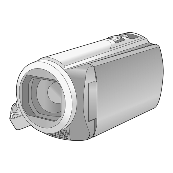
Page 21: Location Of Controls And Components
5 Location of Controls and Components Speaker Lens cover A/V connector [A/V] The lens cover opens in Motion Picture ● Intelligent auto button [iA] Recording Mode or Still Picture Optical Image Stabilizer button Recording Mode. O.I.S.] Lens Battery release lever [BATT] Internal stereo microphones Power button [ HDMI mini connector [HDMI]... - Page 22 DC input terminal [DC IN] Photoshot button [ Zoom lever [W/T] (In Motion Picture Do not use any other AC adaptors except the ● Recording Mode or Still Picture supplied one. Recording Mode) Thumbnail display switch [ Volume lever [ VOL ] (In Playback Mode) Grip belt Adjust the length of the grip belt so that it fits...
- Page 23 Selecting a mode Operate the mode switch to change the mode to Motion Picture Recording Mode Still Picture Recording Mode Playback Mode How to use the touch screen You can operate by directly touching the LCD monitor (touch screen) with your finger. Touch Touch and release the touch screen to select icon or picture.
-
Page 24: About The Touch Menu
About the Touch Menu Touch (left side)/ (right side) of on the Touch Menu to switch the operation icons. It is also possible to switch the operation icons by sliding the Touch Menu right or left while ● touching it. Touch Menu Recording Mode Playback Mode... -
Page 25: Service Mode
6 Service Mode 1. Indication method of the service menu Set the mode switch “Motion Picture Recording” mode. 2. While the power is turned OFF, keep pressing the “Power” button, “Zoom lever” to W side and “intelligent auto/Manual” button for more than 3 seconds until the top screen of the Service Mode Menu being displayed. Service mode menu Screen display Contents... -
Page 26: Built-In Memory Self Check Execution (Hc-V520M Only)
6.1. Built-in Memory Self Check Execution (HC-V520M only) Touch the [ 3 ] of LCD, select Built-in memory self check execution. Operation specifications Indication contents • Built-in memory self check result display Display the Built-in memory self check execution. Displays other than “OK” are abnormalities of Built-in memory. Touch the [ BAK ] of LCD to end the service mode, and then POWER OFF. -
Page 27: Power On Self Check Result Display
6.3. Power ON Self Check Result Display Touch the [ 5 ] of LCD, select Power ON self check result display. Operation specifications Indication contents • Power ON self check result display Function to diagnose correct function of the device and interface between devices result display. Display the following communication test result. -
Page 28: Camera Data Indications While The Video Playback
6.5. Camera data indications while the video playback Touch the [ 12 ] of LCD, select indicating the camera informations while playing back the recorded video. Operation specifications Indication contents • While playing back the recorded videos, the camera informations (Shutter speed, Iris value, White balance and focal length) are superimposed on the LCD screen. -
Page 29: Adjustment Function For The Service
6.6. Adjustment function for the Service Touch the [14] of LCD, select the adjustment function for the service. Operation Specifications (until before the start of the adjustment) Function description The service adjustment do setup and adjustment of the following items required in the field service. For a detailed content, such as the adjustment procedure, refer to “9 Measurements and Adjustments”. -
Page 30: Restore The Backed Up Adjustment Data
6.7. Restore the backed up adjustment data Touch the [15] of LCD, select restoring the backed up adjustment data from SD card to the unit. Operation Specifications Function description Restore the adjustment data to new or repaired Main P.C.B. from SD card that the data backed up from original Main P.C.B. before repairs or replacement. -
Page 31: Touch Panel Calibration
6.8. Touch Panel Calibration Touch the [16] of LCD, select the calibration of touch panel. Operation Specifications Function description Calibrate the touch positions of the touch panel. Press the power button and turn the unit off. 6.9. NFC Initialization (HC-V520/V520 only) Touch the [17] of LCD, select initialization of NFC (Near Field Communication) function. -
Page 32: Service Fixture & Tools
7 Service Fixture & Tools 7.1. When Replacing the Main P.C.B. After replacing the MAIN P.C.B., be sure to achieve adjustment. 7.2. Service Position This Service Position is used for checking and replacing parts. Use the following Extension cables for servicing. Table S1 Extension Cable List Parts No. -
Page 33: Disassembly And Assembly Instructions
8 Disassembly and Assembly Instructions 8.1. Disassembly Flow Chart for the Unit This is a disassembling chart. When assembling, perform this chart conversely. 8.2. PCB Location... -
Page 34: Disassembly Procedure For The Unit
8.3. Disassembly Procedure for the Item Removal Monitor P.C.B. (Fig. D13) 2 Screws (P) Unit Light Guide Plate Unit 8 Locking tabs LCD Panel Unit LCD Case (T) Unit (Fig. D14) FP901 (Flex) Item Removal FP904 (Flex) Side Case-L Unit (Fig. - Page 35 8.3.1. Removal of the Side Case-L Unit (Fig. D2) 8.3.2. Removal of the Top Case Unit (Fig. D1) (Fig. D3)
- Page 36 8.3.3. Removal of the Front Case Unit (Fig. D5) (Fig. D4)
- Page 37 8.3.5. Removal of the Heat Radiation Plate-L Unit and Lens Frame Unit (Fig. D6) 8.3.4. Removal of the Wi-Fi P.C.B. (HC- V520/V520M only), ESD P.C.B. Unit (HC-V520M only) (Fig. D8) (Fig. D7)
- Page 38 8.3.6. Removal of the Lens Unit (Fig. D10) (Fig. D9)
- Page 39 8.3.7. Removal of the SD Holder P.C.B., Main P.C.B. (Fig. D12) (Fig. D11)
- Page 40 8.3.8. Removal of the Monitor P.C.B., Light Guide Plate Unit, LCD Panel Unit. (Fig. D14) (Fig. D13)
- Page 41 (Fig. D15) (Fig. D16)
- Page 42 8.3.9. Removal of the Front Base, Barrier 8.3.10. Removal of the Mic Cover, Front R, Barrier F Ornament Ring, Flare Cut Piece, Microphone Unit, Front Case (Fig. D17) (Fig. D18)
- Page 43 8.3.11. Removal of the MOS Unit, IR Cut Grass (Fig. D19) (Fig. D20)
- Page 44 8.3.12. Removal of the Iris Unit (Fig. D21) (Fig. D22)
- Page 45 8.3.13. Removal of the 2nd Stepping Moter, 3rd Stepping Motor, Focus Motor (Fig. D23) (Fig. D24)
- Page 46 (Fig. D25)
-
Page 47: Measurements And Adjustments
9 Measurements and Adjustments 9.1. Electric Adjustment • Adjustment method is different from a conventional High definition video camera. • An exclusive jig are necessary for electric adjustment. • Connection method of the main unit and an exclusive adjustment jig as follows. 9.1.1. - Page 48 Part Number of jig 1. Basic Jig Item Contents AC adaptor Bandled with camcorder AC Cable Bandled with camcorder HDMI Cable Bandled with camcorder 2. Optical Jig for Camera Adjustment Item Part number Remarks Light box VFK1164TDVLB/RFKZ0523* Need external power supply: 12V ± 0.1V /1.8A or over Collimator with focus chart VFK1164TCM02/VFK1164TCM03 Same as DSC...
- Page 49 [Level Shot Adjutment Chart]...
- Page 50 9.1.2. Adjustment Items Adjustment item as follows.
-
Page 51: Adjustment Procedure
9.1.3. Adjustment Procedure All adjustments except “Touch Panel Calibration”, “Factory Setting” and “NFC Initialization” performs using “14 Adjustment function for the service” in service mode menu. “Touch Panel Calibration” is performed using 16 of service mode menu and “Factory Setting” is performed using 1, “NFC Initializa- tion”... - Page 52 [Adjustment Procedure] Adjustments and settings are performed following order: 1. Filename setting for backup to SD card 2. Model setting 3. Backing up adjustment data to SD card 4. Checking switches 5. Camera adjustment (Iris, Gyro, OIS, Missing pixels compensation) 6.
-
Page 60: Factory Setting
10 Factory Setting 10.1. How To Turn On The Factory Settings? 1. Set the mode switch “Motion Picture Recording” mode. 2. While the power is turned OFF, keep pressing the “Power” button, “Zoom lever” to W side and “intelligent auto/Manual” button for more than 3 seconds until the top screen of the Service Mode Menu being displayed. -
Page 61: What Is The Factory Settings
10.2. What Is The Factory Settings? The factory settings clean up and/or refresh the following settings. 1. MENU, MODE, ADJUSTMENT VALUE. 2. Reset the folder number and file number of still pictures. (Setting the folder number is 100, and file number is 0.) 3. -
Page 62: Block Diagram
11 Block Diagram 11.1. Overall Block Diagram OVERALL BLOCK DIAGRAM NOTE : VIDEO SIGNAL : AUDIO SIGNAL : CLK or CONTROL LINE LENS(F1.8-4.2 50x) IC201 COLOR LCD ZOOM/ MOS IMAGE PANEL IC901 FOCUS IRIS SENSOR LCD COLOR MOTOR/ DRIVER IC202,302 GATE IC Analog X3402... -
Page 63: Camera/System Control Circuit Block Diagram
11.2. Camera/System Control Circuit Block Diagram CAMERA/SYSTEM CONTROL CIRCUIT BLOCK DIAGRAM IC3401 IC201 (MOS IMAGE SENSOR) (MPEG CODEC) (To IC701-49) TOP CASE OPERATION SWITCH UNIT KEYIN4 PW REG3V RL3401 RL3402 RL3403 RL3404 FP6402 BUS240 DOAP BUS240 DAP MODE SWITCH DOAP AJ30 LVACH1DOP S/S SW Wi-Fi... -
Page 64: Video/Audio Signal Process(1) Circuit Block Diagram
11.3. Video/Audio Signal Process(1) Circuit Block Diagram VIDEO/AUDIO PROCESS ( 1 ) CIRCUIT BLOCK DIAGRAM IC3402 IC3403 (DDR SDRAM/1G-bit) (NAND FLASH ROM/1Gbit) JK6003 HDMI MINI CONNECTOR DATA CTL SIG Q3401 ADDRESS CTL SIG DATA 33 36 49 53 56 10 14 59 62 PW 3.2V IC3401... -
Page 65: Video/Audio Signal Process(2) Circuit Block Diagram
11.4. Video/Audio Signal Process(2) Circuit Block Diagram VIDEO/AUDIO PROCESS ( 2 ) CIRCUIT BLOCK DIAGRAM IC901 (LCD COLOR DRIVER) LCD LVDS0P PROTOCOL PARSING, LCD LVDS0N PARITY DETECTION, ADVANCED DESERIALIZER LCD LVDS1P FRAME MIXING, SYNC WARD To IC3401 DECODING (MPEG CODEC) LCD LVDS1N OUTPUT REGISTER... -
Page 66: Lens Drive Circuit Block Diagram
11.5. Lens Drive Circuit Block Diagram LENS DRIVE CIRCUIT BLOCK DIAGRAM IC3401 (MPEG CODEC) Q775 AA30 LEDCONT LEN ZABS LEN P ZABS LEN FP6008 3GZABS LEN ZLEDCONT P 3GZABS LEN ZABS FABS LEN 3G ZLEDCONT P FABS LEN 3G ZABS FLEDCONT LENS TEMP FABS... -
Page 67: Power Supply Circuit Block Diagram
11.6. Power Supply Circuit Block Diagram POWER SUPPLY CIRCUIT BLOCK DIAGRAM CL1341 Please check the Fuse Resistor and IC Protector when an output voltage does not output. PW MOS1.2V JK6401 IP6401 CL1331 NOREG FUSE RESISTOR: PW MOS1.8V (R1261/R1503/R6002) DC IN PW REG1.8V IC PROTECTOR: PW PLL1.1V... -
Page 68: Wiring Connection Diagram
12 Wiring Connection Diagram 12.1. Interconnection Diagram INTERCONNECTION DIAGRAM HC-V520/V520M only BATTERY Wi-Fi P.C.B. MOS UNIT NFC ANT. LENS BARRIER LENS UNIT BATTERY CATCHER P.C.B. Wi-Fi FPC (FOIL SIDE) : (COMPONENT SIDE) P6701 BATT + BATT + BATT - BATT - FP6003 TOP OPERATION UNIT FP6002...
Need help?
Do you have a question about the HC-V520P and is the answer not in the manual?
Questions and answers