
Summary of Contents for Huntingdon Fusion Techniques PurgEye 100
-
Page 1: User Instructions
PurgEye ® 100 IP65 WELD PURGE MONITOR ® USER INSTRUCTIONS Argweld PurgEye Family Range of Weld Purge Monitors ® ® ®... -
Page 2: Table Of Contents
INDEX PAGE 2 Index ..............Introduction and features ........Understanding the monitor before turning on ..Understanding the monitor before turning on continued ............Methods of use ............Turning on the monitor ..........Calibration ............. Maintenance ............Replacing the sensor ..........Warning, use with caution ........ -
Page 3: Introduction And Features
INTRODUCTION and FEATURES PAGE 3 The PurgEye 100 ‘IP65’ Sealed Weld Purge Monitor has been ® ® specifically designed for the welding industry and provides a low cost, high accuracy device for basic Weld Purge Monitoring. The PurgEye 100 IP65 features include: ®... -
Page 4: Understanding The Monitor Before Turning On
UNDERSTANDINg the MONITOR PAGE 4 BEFORE TURNINg ON Sensor Housing Connectors The ‘leak tight’ sensor housing connectors are designed to accept 6 mm OD polyurethane purge gas tubing for its low oxygen outgassing rates and best weld purging results. Small lengths of this tubing will be supplied with your PurgEye ®... -
Page 5: Understanding The Monitor Before Turning On Continued
UNDERSTANDINg the MONITOR PAGE 5 BEFORE TURNINg ON continued The best way to use your Weld Purge Monitor is to connect the ® exhaust tube from your purging system to one of the quick fit connectors on the front of the monitor. Then allow the exhaust gas to flow freely over the sensor, out to atmosphere using the 6”... -
Page 6: Methods Of Use
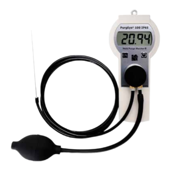
METHODS of USE PAGE 6 Connections with Sampling Bulb Connections with Bulb Pump This diagram shows connections for use with the ‘bulb’ as sampling pump. Sensor Cover Bulb Pump Sample Probe As mentioned above, the PurgEye 100 ‘IP65’ can be used with ®... -
Page 7: Turning On The Monitor
TURNINg ON the MONITOR PAGE 7 Installing the Batteries Remove the battery cover on the rear of the device and install 2 x AA size standard alkaline batteries, ensuring the polarity is correct. Use only alkaline type AA batteries. Be careful not to lose the tiny screw(s). -
Page 8: Calibration
CALIBRATION PAGE 8 Full-Scale Calibration Carefully remove the sensor housing cover (pull slightly and rotate the black round cover to remove) to expose the sensor element to atmospheric oxygen. Replace sensor cover after two minutes. Then press and hold the calibrate button for 5 seconds. After this time period the monitor will read ~20.94%. -
Page 9: Maintenance
MAINTENANCE PAGE 9 Low Sensor and Low Battery Indicators When the instrument displays a flashing “!” in the bottom left corner, it is indicating that it is time to replace the sensor. See spare parts list on page 14. © HFT ®... -
Page 10: Replacing The Sensor
REPLACINg the SENSOR PAGE 10 Installing a New Sensor • Carefully remove the sensor housing cover. • Always ‘gently’ rotate (quarter turn) the sensor housing cover while fitting or removing. • Remove the sensor using the sensor removal tool by hooking it into the groove on the black part of the sensor, then simply rest the removal tool against the monitor and lever the sensor gently upwards. -
Page 11: Warning, Use With Caution
WARNINg, USE with CAUTION PAGE 11 Zero Calibration (Correction) Facility The PurgEye 100 ‘IP65’ Weld Purge Monitor is set for use by ® ® our quality control procedures prior to the product shipping to you. However, occasionally, it may be necessary to use the zero calibration facility. -
Page 12: Zero Calibration
ZERO CALIBRATION PAGE 12 When a new sensor is fitted or where greater accuracy is required at very low readings, you may want to zero the monitor. This is done by first completing the full-scale calibration procedure above and then completing the following steps. 1. -
Page 13: Zero Calibration Continued
ZERO CALIBRATION PAGE 13 continued 6. Once the reading falls below 0.5% the monitor will wait for the reading to stabilise and then take a reference reading, this should take several minutes, the longer the better. Once this is complete the screen will stop flashing ‘CAL’... -
Page 14: Spares And Accessories
SPARES and ACCESSORIES PAGE 14 Part Descriptions Order Code Replacement sensor ..........APIS101 Sensor removal tool ..........APIS102 Protective rubber housing (shown below) ....APIS103 Tripod (medium size) ..........APIS104 Auto break safety wrist and neck strap ..... APIS106 Sampling tube 6 mm OD x 2 m length ......APIS108 ‘Leak Tight’... -
Page 15: Troubleshooting And Fault Finding
TROUBLESHOOTINg and PAGE 15 FAULT FINDINg A Quick guide in the Event of Problems If the reading does not fall below 20.9% after a reasonable purge time, or in the event that your reading does not pass your expected level of oxygen, please do the following: •... -
Page 16: The Family Series Of Weld Purge Monitors
PURgEYE FAMILY RANgE of PAGE 16 Argweld ® ® WELD PURgE MONITORS ® The World standard PurgEye 100 IP65 Hand Held ® • Push button ‘Auto Calibration’ feature at precisely 100 ppm as well as at ambient (20.94%). • Leak tight probe assembly. • Low battery indicator and low sensor indicator. • Increased sensor reading range. • Quick connect/disconnect leaktight fittings for gas purge tubing. The PurgEye 200 IP65 Hand Held with PurgeNet™... -
Page 17: Other Languages
Other LANgUAgES in PROgRESS PAGE 17 Les autres langues sont actuellement dans le progrès. Pour le moment, s’il vous plaît contacter votre Distributeur local Andere Sprachen sind momentan im Gange. Kontaktieren Sie vorläufig, bitte Ihren örtlichen Verteiler Otros idiomas son actualmente en progreso. Para ahora, contacta por favor su Distribuidor local... -
Page 18: Customer Support And Worldwide Care
CUSTOMER SUPPORT and PAGE 18 WORLDWIDE CARE For further information and support, please contact us at: Internet: www.huntingdonfusion.com Email: hft@huntingdonfusion.com Tel: +44 (0) 1554 836 836 Worldwide Offices, Partners and Distributors are listed on our website or contact us and we will direct you to the correct location... -
Page 19: Warranty
Should you encounter a problem with your product, please notify us immediately upon receipt. Huntingdon Fusion Techniques HFT warrants this product to be ® free of defects in workmanship and material, with exceptions stated below. - Page 20 Tel +44 (0) 1554 836 836 Fax +44 (0) 1554 836 837 www.huntingdonfusion.com Email hft@huntingdonfusion.com E&OE Copyright © HFT . All rights reserved. ® This publication may not be reproduced by any means without the written permission of Huntingdon Fusion Techniques HFT ®...
Need help?
Do you have a question about the PurgEye 100 and is the answer not in the manual?
Questions and answers