
Related Manuals for Rockwell Automation 1763-L16AWA


Summary of Contents for Rockwell Automation 1763-L16AWA
-
Page 1: Table Of Contents
Installation Instructions MicroLogix 1100 Programmable Controllers Catalog Numbers 1763-L16AWA, 1763-L16BWA, 1763-L16BBB, 1763-L16DWD Topic Page Important User Information Additional Resources Overview Controller Description Hazardous Location Considerations Mounting the Controller Connecting 1762 I/O Expansion Modules Wiring the Controller Specifications... -
Page 2: Important User Information
In no event will Rockwell Automation, Inc. be responsible or liable for indirect or consequential damages resulting from the use or application of this equipment. -
Page 3: Additional Resources
Guidelines 1770-4.1 techniques. If you would like a manual, you can: • download a free electronic version from the internet: http://literature.rockwellautomation.com • purchase a printed manual by contacting your local Allen-Bradley distributor or Rockwell Automation representative Publication 1763-IN001C-EN-P - June 2015... -
Page 4: Overview
Overview MicroLogix 1100 controllers are suitable for use in an industrial environment when installed in accordance with these instructions. Specifically, this equipment is intended for use in clean, dry environments (Pollution degree 2 ) and with circuits not exceeding Over Voltage Category II (IEC 60664-1). -
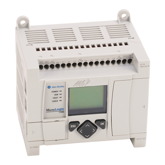
Page 5: Controller Description
Controller Description Item Description Output Terminal Block Battery Connector Bus Connector Interface to Expansion I/O Battery Input Terminal Block LCD Display LCD Display Keypad (ESC, OK, Up, Down, Left, Right) Status LEDs Memory Module Port Cover -or- Memory Module DIN Rail Latches RS-232/485 Communication Port (Channel 0, isolated) Ethernet Port (Channel 1) Shipped with controller. -
Page 6: Hazardous Location Considerations
Catalog Description Number Input Digital Analog Digital Comm. Power Inputs Inputs Outputs Ports 1763-L16AWA 120/240V ac (10) 120V ac (2) voltage input (6) relay (1) RS-232/485 combo All individually (isolated) 0...10V dc isolated (1) Ethernet 1763-L16BWA 120/240V ac (6) 24V dc... - Page 7 EXPLOSION HAZARD WARNING • Substitution of components may impair suitability for Class I, Division 2. • Do not replace components or disconnect equipment unless power has been switched off. • Do not connect or disconnect components unless power has been switched off. •...
-
Page 8: Mounting The Controller
Use only the following communication cables in Class I, Division 2 hazardous locations. Environment Classification Communication Cables Class I, Division 2 Hazardous Environment 1761-CBL-AC00 Series C or later 1761-CBL-AM00 Series C or later 1761-CBL-AP00 Series C or later 1761-CBL-PM02 Series C or later 1761-CBL-HM02 Series C or later 1761-CBL-PH02 Series A or later 1761-CBL-AH02 Series A or later... - Page 9 Drilled fragments that fall into the controller could cause damage. Do not drill holes above a mounted controller if the protective debris strips have been removed. Mounting Dimensions 1763-L16AWA, 1763-L16BWA, 1763-L16BBB, 1763-L16DWD Dimension 1763- L16AWA...
- Page 10 Controller Spacing The controller mounts horizontally, with the expansion I/O extending to the right of the controller. Allow 50 mm (2 in.) of space on all but the right side for adequate ventilation, as shown below. Side Bottom DIN Rail Mounting The maximum extension of the latch is 14 mm (0.55 in.) in the open position.
- Page 11 Follow these steps to install your controller on the DIN rail. 1. Mount your DIN rail. (Make sure that the placement of the controller on the DIN rail meets the recommended spacing requirements. See Controller Spacing on page 12. Refer to the mounting template inside the back cover of this document.) 2.
- Page 12 Panel Mounting Mount to panel using #8 or M4 screws. Follow these steps to install your controller using mounting screws. 1. Remove the mounting template from inside the back cover of this document. 2. Secure the template to the mounting surface. (Make sure your controller is spaced properly.
- Page 13 Follow these steps to connect the replaceable battery. 1. Insert the replaceable battery wire connector into the battery connector. 2. Secure the battery connector wires along the wire guide as shown below. Replaceable Battery Pocket Replaceable Battery Wire Guide Battery Connector Wires Battery Wire Connector Battery Connector Publication 1763-IN001C-EN-P - June 2015...
-
Page 14: Connecting 1762 I/O Expansion Modules
Connecting 1762 I/O Expansion Modules ATTENTION Remove power to the system before installing or removing expansion I/O or damage to the controller may result. Connect 1762 I/O after mounting the controller. 1. Remove the expansion port cover to install expansion I/O modules. 2. -
Page 15: Wiring The Controller
Wiring the Controller Terminal Block Layouts The shading in the following terminal block illustrations indicates which terminals are tied to which commons. 1763-L16AWA Input Terminal Block USED USED IV1(+) IV2(+) L2/N 100-240 VAC USED USED Output Terminal Block 1763-L16BWA Input Terminal Block... - Page 16 1763-L16DWD Input Terminal Block USED USED IV1(+) IV2(+) + 12/24V - DC IN USED USED Output Terminal Block Wire Requirements Wire Type Wire Size (2 wire maximum per terminal) 1 wire per terminal 2 wire per terminal Solid Cu-90 °C (194 °F) 12...20 AWG 16...20 AWG Stranded...
- Page 17 2. Insert it into an open clamp. 3. Using a small, flat-blade screwdriver, tighten the terminal screw. To ensure that the wire conductor is secured inside the clamp, tighten it to the rated torque, 0.56 Nm (5.0 in-lb). The diameter of the terminal screw head is 5.5 mm (0.220 in.). Screw-cage clamp terminal block Surge Suppression Inductive load devices such as motor starters and solenoids require the use of some...
- Page 18 Grounding the Controller In solid-state control systems, grounding and wire routing helps limit the effects of noise due to electromagnetic interference (EMI). Run the ground connection from the ground screw of the controller to the ground bus prior to connecting any devices. Use AWG #14 wire. For ac-powered controllers, this connection must be made for safety purposes.
- Page 19 Wiring Your Analog Channels Analog input circuits can monitor voltage signals and convert them to serial digital data. Sensor 2 (V) Voltage Sensor 1 (V) Voltage IV1(+) IV2(+) The controller does not provide loop power for analog inputs. Use a power supply that matches the transmitter specifications as shown below.
- Page 20 • install the MicroLogix 1100 system in a properly rated (NEMA) enclosure. Make sure that the MicroLogix 1100 system is properly grounded. • use Belden cable #8761 for wiring the analog channels, making sure that the drain wire and foil shield are properly earth grounded. •...
-
Page 21: Specifications
Specifications General Specifications Description 1763- L16AWA L16BWA L16BBB L16DWD Dimensions Height: 90 mm (3.5 in.), 104 mm (4.09 in.) (with DIN latch open) Width: 110 mm (4.33 in.), Depth: 87 mm (3.43 in.) Shipping Weight 0.9 kg (2.0 lbs) Number of I/O 12 inputs (10 digital and 2 analog) and 6 outputs Power Supply 100...240V ac (-15%, +10%) at 47...63 Hz... - Page 22 General Specifications Description 1763- L16AWA L16BWA L16BBB L16DWD Shock, 50 g panel mounted (40 g DIN Rail mounted); 3 pulses each direction, Nonoperating each axis Terminal Screw 0.56 Nm (5.0 in-lb) rated Torque Certifications UL Listed Industrial Control Equipment for use in Class 1, Division 2, Hazardous Locations, Groups A, B, C, D C-UL Listed Industrial Control Equipment for use in Canada CE marked for all applicable directives...
- Page 23 +10% for 15 minutes, -10% for 15 minutes dc Power Supply Input: voltage fluctuation: +20% for 15 minutes, -20% for 15 minutes Input Specifications Digital Inputs Description 1763-L16AWA 1763-L16BWA, -L16BBB Inputs 0 through 3 Inputs 4 and higher (4 high-speed dc inputs) (6 standard dc inputs) On-State Voltage 79 ...132V ac...
- Page 24 Digital Inputs Description 1763-L16AWA 1763-L16BWA, -L16BBB Inputs 0 through 3 Inputs 4 and higher (4 high-speed dc inputs) (6 standard dc inputs) Off-State Leakage 2.5 mA max. 1.5 mA max. Current Nominal 12 kΩ at 50 Hz 3.1 kΩ 3.1 kΩ...
- Page 25 Analog Inputs Description 1763-L16AWA, -L16BWA, -L16BBB, -L16DWD Voltage Input Range 0 ...10.0V dc - 1 LSB Type of Data 10-bit unsigned integer Input Coding (0 to 10.0V dc - 1 LSB) 0 ...+1,023 Voltage Input Impedance 210 kΩ Input Resolution...
- Page 26 Relay Contact Ratings Maximum Volts Amperes Amperes Volt-Amperes Continuous Make Break Make Break 7.5 A 0.75 A 2.5 A 1800 VA 180 VA 240V AC 15.0 A 1.5 A 2.5 A 1800 VA 180 VA 120V AC 0.22 A 1.0 A 28 VA 125V DC Pilot Duty Rating: (ordinary location) –...
- Page 27 General Description 1763 -L16AWA, -L16BWA, -L16BBB -L16DWD Relay Outputs Turn On Time/Turn Off Time 10 msec (maximum) Relay life - Electrical (Resistive Load) Refer to Relay Life Chart Relay life - Mechanical 10,000,000 cycles Load Current 10 mA (minimum) 3.0 A above 40 °C. Scan time dependent.
- Page 28 Relay Life Chart 1000 250 VAC resistive load 250 VAC induction load (cosφ=0.4) 30 VDC resistive load Switching capacity(A) BBB FET Output Specifications Description General Operationl High Speed Operation (Output 2 and 3 Only) Power Supply Voltage 24V dc (-15%, +10%) On-State Voltage Drop: •...
- Page 29 BBB FET Output Specifications Description General Operationl High Speed Operation (Output 2 and 3 Only) Maximum Output Current (temperature dependent): FET Total Current FET Current per Point (1763-L16BBB) (1763-L16BBB) 1.75 1.5A, 30˚C (86˚F) 1.25 0.75A, 65˚C (149˚F) 3.0A, 30˚C (86˚F) 0.75 Valid Valid...
- Page 30 Working Voltage Working Voltage (1763-L16AWA) Description 1763-L16AWA Power Supply Input to Verified by one of the following dielectric tests: 1836V ac for 1 second or Backplane Isolation 2596V dc for 1 second 265V ac Working Voltage (IEC Class 2 reinforced insulation)
- Page 31 Notes:...
- Page 32 Línea central del riel DIN. E/A - Linea centrale della guida DIN. Erweiterungsmodule linha de centro do trilho DIN. l'espansione dei moduli I/O de expansión de E/S 100.00 mm (3.937 in.) de expa nsão de E/S 1763-L16AWA 1763-L16BWA 1763-L16BBB...
- Page 33 S/MASK: S/MASK: G/WAY: G/WAY:...
- Page 34 New Product Satisfaction Return Rockwell Automation tests all of its products to ensure that they are fully operational when shipped from the manufacturing facility. However, if your product is not functioning and needs to be returned, follow these procedures.
Need help?
Do you have a question about the 1763-L16AWA and is the answer not in the manual?
Questions and answers