Advertisement
ATR-30 Instruction Manual
1.0
INTRODUCTION
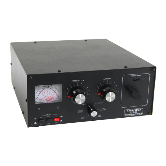
The ATR-30 is a high power antenna tuner. The ATR-30's roller inductor "T" matching network
continuously tunes all frequencies from 1.8 through 30 MHz. It also features a built-in 3 kilowatt peak or
average detecting directional power meter. The ATR-30 has rear panel connectors for coaxial and wire
feedlines. A heavy duty, high voltage insulated, current-type balun allows use with balanced feedlines.
Properly tuned, the ATR-30 safely operates on all bands with RF power levels (CW or SSB) of 3
kilowatts with load impedances from 35-500 ohms. Matching range also extends from one ohm to 2500
ohms (5 ohms to 500 ohms on 160 meters) at slightly reduced power ratings. Peak and average forward
power, reflected power, and SWR are displayed on an illuminated cross-needle meter.
An internal six position antenna-selector switch selects three coaxial line outputs, or a single wire line-
balanced line output. Two coaxial line outputs, ANTENNA 1 and 2, are available in either "tuned"
(with tuner's matching network in line) or "direct" (no matching circuit) configurations.
Coaxial output port ANTENNA 3 is available only as a direct (no matching system) configuration.
WIRE / BALANCED LINE positions are available only as "tuned" configurations.
1.1
Understanding Power Ratings
Unlike amateur radio service amplifiers (commonly rated in RF power output delivered to 50 ohm
resistive loads), tuners have no standard power rating method. Power level descriptions (i.e. "3 kW
Tuner") used for tuners often carry over from the time when amplifiers were rated by peak power input.
For example, the Kilowatt Johnson Matchbox was deigned to handle a typical 1000 watt dc input plate
modulated AM transmitter. Such transmitters developed 3000 watts PEP RF output on AM. Matching
tuners were called one kilowatt tuners.
Years later SSB became popular. The Heathkit SB-220 was called a two kilowatt amplifier, even though
rated CW output was approximately 600 watts. Tuners from the same era were called 2 kilowatt tuners,
because they safely handled the 2 kilowatt PEP input SB-220. The 2 kW tuner only had to handle 600
watts of CW and 1200 watts PEP SSB to be compatible with a 2 kW amplifier of the same era.
Around 1980, the FCC changed the amateur radio power rating system from dc power amplifier input
power to RF envelope (output) power. Most tuners stayed with the old system, and no longer follow
amplifier power ratings. Typical "1500 watt tuners" safely handle only 400-600 watts CW, and 600-900
watts PEP SSB.
Note: This tuner is rated by true RF output power, not by the old method of using amplifier peak input
power.
Load conditions and control settings greatly affect tuner power ratings. T-networks typically handle
more power on higher frequency bands into higher load impedances. The worst operating condition (for
T network tuners) is a low-impedance capacitive-reactance load. T-network tuners handle the least
power on 160 meters with low-impedance capacitive-reactive loads.
Follow the guidelines in this manual to avoid exceeding the ratings of this tuner!
1
Ameritron Antenna Tuner
Advertisement
Table of Contents

Related Manuals for AMERITRON ATR-30


Summary of Contents for AMERITRON ATR-30
- Page 1 A heavy duty, high voltage insulated, current-type balun allows use with balanced feedlines. Properly tuned, the ATR-30 safely operates on all bands with RF power levels (CW or SSB) of 3 kilowatts with load impedances from 35-500 ohms. Matching range also extends from one ohm to 2500 ohms (5 ohms to 500 ohms on 160 meters) at slightly reduced power ratings.
- Page 2 COAX DIRECT positions of the antenna selector. The wattmeter is active in all six positions of the ANTENNA SELECTOR switch. The ATR-30 must have a power source, or the meter won’t function. Power can be provided by an external 12 Vdc supply (negative ground only) or an internal 9 Volt “transistor radio” battery. The meter lamp will not illuminate unless an external supply is used.
-
Page 3: Installation
ATR-30 Instruction Manual Ameritron Antenna Tuner The ANTENNA SELECTOR selects one of 3 rear panel SO-239 coaxial connectors or the wire-type wing-nut connections. Of the three rear panel coaxial connectors, only COAX 1 and COAX 2 connectors are available using the matching network in the tuner. COAX 3 is bypass only, with no tuning functions available. - Page 4 ATR-30 Instruction Manual Ameritron Antenna Tuner The roller inductor has maximum inductance when fully counter-clockwise (turns counter 000) and minimum inductance when fully clockwise (turns counter approximately 87) on the reference counter. The capacitors have maximum capacitance at 0 and minimum capacitance at 10. In simple language, as frequency is increased normal control operating positions rotate clockwise.
-
Page 5: Operating Hints
ATR-30 Instruction Manual Ameritron Antenna Tuner 9. After adjusting the tuner for minimum SWR, the amplifier may be turned on. The METER switch should be placed in the HI position, and the amplifier tuned according to the manufacturer's instructions. 10. For quick retuning of the tuner, record the control settings for each band and use them as starting points. -
Page 6: Antenna System Hints
CAUTION: For operator safety, a good outside earth ground or water pipe ground should always be installed and connected to the case of the ATR-30. Make certain the safety ground also connects to the transmitter and other station accessories. wing... - Page 7 ATR-30 Instruction Manual Ameritron Antenna Tuner coaxial cables, even when feeding groundplane or gamma matched antennas, since systems are seldom perfectly designed or constructed. 3. Avoid feeding unbalanced antennas (like verticals) with balanced feedlines. Even if a good balun is used at the tuner, the line will still radiate.
-
Page 8: Technical Assistance
Ameritron at 601-323-8211. You will be best helped if you have your unit, manual and all information on your station handy so you can answer any questions the technicians may ask. - Page 10 ATR-30 Instruction Manual Ameritron Antenna Tuner Tuning Log Use the log below to record settings for your antennas. You may want to copy this chart and post it by your tuner. Antenna Frequency Transmitter Antenna Inductor type (MHz) 3.75 3.75 3.75...
Need help?
Do you have a question about the ATR-30 and is the answer not in the manual?
Questions and answers