Table of Contents
Advertisement
Advertisement
Table of Contents

Related Manuals for Lumel N43


Summary of Contents for Lumel N43
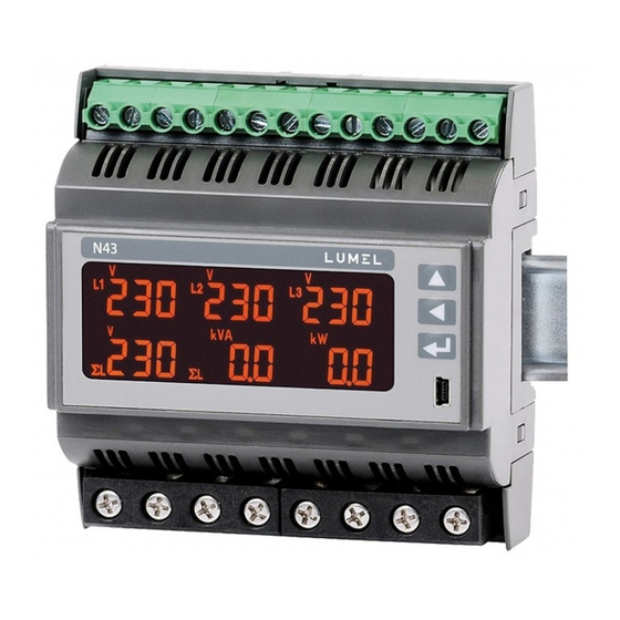
- Page 1 RAIL MOUNTED POWER NETWORK METER USER’S MANUAL...
-
Page 3: Table Of Contents
5. METER DESCRIPTION ..............10 5.1 Current inputs ..............10 5.2 Voltage inputs ..............10 5.3 Connection diagramms ............. 10 6. N43 PROGRAMMING ..............16 6.1 Front panel ................16 6.2 Power-on messages ............18 6.3 Operating modes ..............19 6.4 Measure mode .............. - Page 4 8.1 RS-485 interface - list of parameters ........ 46 8.2 USB interface - list of parameters ........47 8.3 Examples of registers’ readout and write ......48 8.4 Map of N43 meter registers ..........54 9. ERROR CODES ................76 10. ACCESSORIES ................77 11.
-
Page 5: Application
1. APPLICATION The N43 meter,assembled on a rail, is a programmable digital instrument designed for the measurement of 3-phase, 3 or 4-wire power network parameters in balanced or unbalan- ced systems. The measured values are displayed on a dedicated LCD display. The meter enables control and optimization of the power electronic devices, systems and industrial installations. -
Page 6: Meter Set
- voltage and current inputs, - RS-485, - USB, - pulse output OC, - alarm outputs. 2. METER SET Complete set of the meter includes: - N43 Meter....... 1 pc - user’s manual ......1 pc - CD .......... 1 pc... -
Page 7: Basic Requirements, Operational Safety
3. BASIC REQUIREMENTS, OPERATIONAL SAFETY In terms of operational safety it meets the requirements of the EN 61010-1 standard. Comments concerning safety: • The meter should be installed and connected only by a qualifi ed personnel. All relevant safety measures should be observed during installation. -
Page 8: Installation
/direct measurement/. The meters should not be installed on the rail in direct contact with other devices that emit heat (e.g. other N43 meters). There must be a minimum 5 mm spacing between devices in order to enable heat transfer from a housing to the environ- ment. - Page 9 Fig. 1. Meter dimensions...
-
Page 10: Meter Description
5. METER DESCRIPTION 5.1 Current inputs All current inputs are galvanically isolated (internal current transformers). The meter is adapted for direct connections /up to 63 A/ or to work with external measuring current transformers /version 1 A/5 A /. Displayed current values and derivative quan- tities are automatically converted in relation to the introduced external current transformer ratio. -
Page 11: Connection Diagramms
5.3 Connection diagrams a) Meter connection diagrams in the 3-phase 4-wire network Direct measurement in 4-wire network... - Page 14 b) Meter connection diagrams in the 3-phase 3-wire network...
-
Page 16: N43 Programming
6. N43 PROGRAMMING 6.1 Front panel Fig. 3. Front panel... - Page 17 Front panel description: increase value button active energy export and right displacement decrease value button active energy import and left displacement symbol of energy / confi rm button (ENTER) reactive inductive power symbol of energy / USB socket reactive capacity power 6 fi...
-
Page 18: Power-On Messages
Fig. 4. Message after starting the meter After switching the supply on, the meter performs a display test and displays the N43 meter name, build and current software as well as bootloader version. where: n43 – meter type, 5A 230V – version rEu revision 0.10 program version number... -
Page 19: Operating Modes
6.3 Operating modes Switching Change Display of maximum, a supply on of displayed minimum value -erasing pages 3 sec. MEASURE mode Erasing of alarm latch 3 sec. Enter a code Code Selection of Set parameters Pages con guration mode Output parameters mode Alarm parameters mode Meter parameters mode Selection of pages PAGn... -
Page 20: Measure Mode
6.4 MEASURE Mode In Measure mode the values are displayed according to the pages that are preset at the factory or confi gured by the user in Pages Programming PAG. Changing the page is done by pressing the The sequence of displayed pages is according to a table created in PAG mode. - Page 21 Voltage [V] Current [A] Active power [W] Reactive power [VAr] Apparent power [VA] Floating point Active energy [Wh] Reactive energy [VArh] Apparent energy [VAh] Fig 6. Formats of displayed values. Exceeding of the upper or lower indication range is signaled on the display by upper horizontal lines.
- Page 22 Current value in the neutral wire I calculated from phase current vectors is available in the registry 7544 of the serial interface. The alarm switching on is signaled by the lighting of the Aln inscription (n= 1..3). The end of alarm duration at the alarm signalization latch switched on, is indicated by the pulsation of the Aln inscription (n= 1..3).
- Page 23 L1 phase active power √ P factor (PF1=P1/S1) tgϕ factor of L1 phase √ (tg1=Q1/P1) 08 L1 phase voltage THD √ D 09 L1 phase current THD √ D 10 L2 phase voltage (k)V √ 11 L2 phase wire current (k)A √...
- Page 24 tgϕ factor of L3 phase √ (tg3=Q3/P3) √ 26 L3 phase voltage THD D 27 L3 phase current THD √ D √ √ f1,f2,f3,f4,f5 28 3-phase mean current* (k)A ΣL S √ √ f1,f2,f3,f4,f6 29 3-phase active power (M,k)W ΣL 30 3-phase reactive power (M,k)VAr...
-
Page 25: Parameter Settings
Active 3-phase output ΣL √ √ f5-f6 (M,k)Wh energy Reactive 3-phase ΣL √ √ f5-f6 En (M,k)VArh inductive energy Reactive 3-phase ΣL √ √ f5-f6 En (M,k)VArh capacity energy 3-phase apparent √ √ f5-f6 (M,k)VAh ΣL energy Time – hours, minutes, √... - Page 26 If the wrong access code is entered, only monitoring of the para- meters is possible without possibility of changing them. Err cod is displayed and then rE Ad Par. Free eCon software can also be used for confi guration of the N43 meters, it is available on the website www.lumel.com.pl.
- Page 27 Fig. 8. Programming matrix...
-
Page 28: Settings Of Meter Parameters
6.5.1 Setting of Meter Parameters After entering the SEt procedure select with the button mode Par and press Buttons set the requested values. The active position is signaled by the cursor. The set value can be accepted by the . Exit from the SEt procedure follows after pres- button sing simultaneously the buttons or waiting approx. - Page 29 Current transformer 1 .. 10000 ratio Voltage transformer 0,1…4000,0 ratio Averaging time of Averaging time active power /Demand integration t_15, t_30, P Demand, apparent t_15 time/ t_60 power S Demand, current I Demand t_15, t_30, t_60 Averaging synchro- nization with the on/oFF sn...
-
Page 30: Settings Of Output Parameters
The automatic erasing of the energy is done with a change of voltage or current ratio. During the acceptation the value insertion possibility in the range is checked. If the set value falls outside the allowable range, the meter remains in parameter setting mode and the value is set to the highest possible value (when entered value is too high) or lowest possible value (when it is too low). -
Page 31: Settings Of Alarm Parameters
6.5.3 Setting of alarm parameters In the options select the ALn mode and confi rm your choice by pressing the button Table 4 AL1=U123 Quantity on the 0..42 code as in Tab. 5 AL2=IS n alarm output AL3=P n-on, n-oFF, 2 Alarm type on,oFF, H-on, Fig. - Page 32 Alarm re-activa- 0 … 3600 in seconds tion lock When alarm signali- zation latch function is enabled and the alarm state ends, alarm symbol is not turned off but begins to fl ash. Alarm symbol fl ashes until it is turned off by Alarm signaliza- pressing the buttons on, oFF...
- Page 33 Entering the value Aon lower than AoF switches the alarm off. a) n-on Relay enabled b) n-oFF c) On...
- Page 34 d) OFF Fig. 9. Alarm types: a)n-on, b) n-oFF, c) On, d) OFF. Remaining types of the alarm: • H-on – always enabled; • H-oFF – always disabled. Example no 1 of alarm setting: Set alarm n-on type for monitored quantity P – 3-phase active power, Version: 5 A;...
- Page 35 Selection of quantities on the alarm outputs: Table 5 Item/ value in the Dis- Value needed for calcula- register played Quantity type tions of percentage of the 4014, element alarm values (100 %) 4022, 4030 no quantity /alarm disabled/ none L1 phase voltage Un [V] * L1 phase wire current...
- Page 36 L2 phase voltage Un [V] * L2 phase wire current In [A] * L2 phase active power Un x In x cos(0°) [W] * L2 phase reactive power Un x In x sin(90°) [VAr] * L2 phase apparent power Un x In [VA] * L2 phase power factor (PF) tgϕ...
- Page 37 THDI3 L3 phase current THD 100.00% mean 3-phase voltage Un [V] * mean 3-phase current In [A] * 3-phase active power 3 x Un x In x cos(0°) [W] * (P1+P2+P3) 3-phase reactive power 3 x Un x In x sin(90°) (Q1+Q2+Q3) [VAr] * 3-phase apparent power...
-
Page 38: Pages Confi Guration Mode
6.5.4 Pages confi guration mode For the meter 1...12 user pages can be programmed or selected from 12 manufacturer’s default pages. The monitored values are shown in Table 1. In the options, select the PAG mode and confi rm your choice by pressing the button Buttons allow to select the page number to edit,... - Page 39 Pages programming Table 6 Manu- Parameter Desig- Range Notes/description facturer name nation value oFF – off, on – on, Display 1..60 – illumination time panel illumi- lgt oFF,1…60, on (in seconds) from pressing nation the button oFF– disabled, oFF, on, on –...
- Page 40 oFF– disabled, oFF, on, on – enabled, Page 5 P confi g confi g – editing a selected page oFF– disabled, oFF, on, on – enabled, Page 6 P confi g confi g – editing a selected page oFF– disabled, oFF, on, on –...
- Page 41 Manufacturer settings are shown below: V V V V V V q VAr V q VAr i A i A i A P W P W P W iS A q VAr q VAr P...
- Page 42 q VAr q VA q VAr S VA iDM A hh.mm.ss SDM VA EnP kWh Visualization of the manufacturer’s page P02: Fig.11 Visualization of the manufacturer’s page P02...
-
Page 43: Software Upgrades
7. SOFTWARE UPGRADE A feature implemented in the N43 meters enables to upgrade fi rmware using a PC with eCon software installed. Free eCon software and the update fi les are available at www.lumel.com.pl. Updating can be done directly via USB or RS485 interface using RS485 to USB converter, e.g.: PD10... - Page 44 After launching eCon software, set in the settings required serial port, baud rate, mode and address of the meter. Next, select the N43 meter and click Confi g. Click the down arrow icon to read all of the settings then the disk icon to save the settings to a fi...
- Page 45 opened message is displayed. Press the Send button. When upgrade is successfully completed, the meter begins normal operation while the information window displays Done message and upgrade elapsed time. The next update can only be done via a USB interface in case of a failed upgrade. After the LU window is closed, go to parameter group Restoring manufac- turer settings, select the option and press the button Apply.
-
Page 46: Serial Interfaces
8. SERIAL INTERFACES 8.1 RS-485 INTERFACE – list of parameters The implemented protocol is compliant with the PI-MBUS-300 Rev G specifi cation of Modicon. List of N43 meter serial interface parameters: • identifi er 0xCF • meter address 1..247 •... -
Page 47: Usb Interface - List Of Parameters
8.2 USB INTERFACE – list of parameters USB interface is dedicated only to the confi guration of meter parameters. • identifi er 0xCF • meter address • baud rate 9.6 kbit/s, • operating mode Modbus RTU, • transmission mode • max. -
Page 48: Examples Of Registers' Readout And Write
8.3 Examples of registers’ readout and write Readout of n-registers (code 03h) Example 1. Readout of two 16-bit integer registers, starting with the register address 0FA0h (4000) - register values 10, 100. Request: Device Fun- Register address Number of registers address ction checksum... - Page 49 Example 2. Readout of two 32-bit fl oat registers as a combination of two 16-bit registers, starting with the register address 1B58h (7000) - register values 10, 100. Request: Register Number Device Fun- address of registers chceck- address ction C3 3E Response: Value Value...
- Page 50 Example 3. Readout of two 32-bit fl oat registers as a combination of two 16-bit registers, starting with the register address 1770h (6000) - register values 10, 100. Request: Register Number Device Fun- address of registers chceck- address ction 4066 Response: Value Value...
- Page 51 Example 4. Readout of two 32-bit fl oat registers, starting with the regi- ster address 1D4Ch (7500) - register values 10, 100. Request: Register Number Device Fun- address of registers chceck- address ction 03 B0 Response: Value from the Value from the register register 1D4C (7500) chce-...
- Page 52 Response: Register Number Device Fun- address of registers chceck- address ction CA 54 Writing to n-registers (code 10h) Example 6. Writing two registers starting with the register address 0FA3h (4003). Writing the values 20, 2000. Request: Value Value for the for the registers registers...
- Page 53 C0 2C Response: Information fi eld of the device software version (e.g. „-1.00 b-1.06” - N43 device with software version 1.00 and bootloader version 1.06) chceck- E0 24 4E 34 33 20 2D 31 2E 30 30 20...
-
Page 54: Map Of N43 Meter Registers
8.4 Map of N43 meter registers In the N43 meter, data are placed in 16 and 32-bit registers. Process variables and meter parameters are placed in the address area of registers in a way depended on the variable value type. Bits in 16-bit registers are numbered from the youngest to the oldest (b0-b15). - Page 55 Value is set in the two following 16-bit regi- 7000 Float sters. These registers contain the same data – 7129 (2x16 bits) as 32-bit registers from 7500 – 7564 range. Readout registers. Bit sequence (3-2-1-0) Value set in the 32-bit register. Register 7500 Float description is presented in Table 8.
- Page 56 Input range: 1 A or 5 A: 0 - 1 A, 1 - 5 A (for version In 4004 1A/5A); 63A: 0 – 63A, 1 -63A (for version In 63A); 4005 1...10000 Current transformer ratio 4006 1...40000 Voltage transformer ratio *10 Averaging time of active power, apparent power and 4007...
- Page 57 Erasing averaged parameters 4011 P Demand, S Demand, I Demand 4012 Min, max erasing Erasing alarm signalization 4013 latch Alarm output 1 - value on out- 4014 0.1..42 put (code as in Table 5) Alarm output 1 - type: 4015 0...5 0 –...
- Page 58 4021 Alarm 1 signalization latch Alarm output 2 - value on out- 4022 0.1..42 put (code as in Table 5) Alarm output 2 - type: 4023 0..5 0 – n-on, 1– n-oFF, 2 – on, 3 – oFF, 4 – H-on, 5 – H-oFF Alarm output 2 - lower value of 4024 RW -1440..0..1440 [...
- Page 59 Alarm output 3 - type: 0 – n-on, 4031 0..5 1– n-oFF, 2 – on, 3 – oFF, 4 – H-on, 5 – H-oFF Alarm output 3 - lower value of 4032 -1440..0..1440[ the alarm switch of the rated input range Alarm output 3 - upper value 1100 -1440..0..1440...
- Page 60 Upgrade change of transmis- 4042 sion parameters Standard parameters save (complete with resetting ener- 4043 gy as well as min, max and mean power to 0) 4044 reserved 4045 0...2359 Hour *100 + Minutes 4046 reserved 4047 reserved Consumed active energy, 4048 0..152 two older bytes...
- Page 61 Reactive capacity energy, 4054 0..152 two older bytes Reactive capacity energy, 4055 0..65535 two younger bytes Apparent energy, two older 4056 0..152 bytes Apparent energy, two younger 4057 0..65535 bytes Status Register 1 – see des- 4058 0..65535 cription below Status Register 2 –...
- Page 62 Energy is made available in hundreds of watt-hours (var-hours) in double 16-bit register, and for this reason, one must divide them by 10 when calculating values of particular energy from registers, e.g.: Consumed active energy = (reg. value 4038 x 65536 + reg.
- Page 63 Bit 9 Bit 8 voltage range 57.7 V~ 230 V~ 290 V~ reserved Bit 7 – „1” – averaging interval has not ended Bit 6 – „1” – frequency for THD calculation outside ranges: 48 – 52 for 50 Hz, 58 –...
- Page 64 Status Register 2 – alarms (address 4059, R): Bity 15 ... 7 - reserved Bit 6 – „1” – alarm 3 signalization Bit 5 – „1” – alarm 2 signalization Bit 4 – „1” – alarm 1 signalization Bit 2 – „1” – alarm 3 activated Bit 1 –...
- Page 65 4302 0...0x0FFF Enabling page display 0x0FFF Bit0 – page 1, Bit1 – page 2, ... 4303 0, 01..09, 28..33, Page 1 display 1 35, 38 4304 0, 10..18, 28..33, Page 1 display 2 36, 38 4305 0,19..33, 37, 38 Page 1 display 3 4306 0, 28..34, 38..41 Page 1 display 4...
- Page 66 4316 0, 29 Page 2 display 6 4317 0, 01..09, 28..33, Page 3 display 1 35, 38 4317 0, 01..09, 28..33, Page 3 display 1 35, 38 4318 0, 10..18, 28..33, Page 3display 2 36, 38 4319 00,19..33, 37, 38 Page 3 display 3 4320 00, 28..34, 38..41...
- Page 67 4330 00, 29 Page 4 display 6 4331 00, 01..09, Page 5 display 1 28..33, 35, 38 4332 00, 10..18, Page 5 display 2 28..33, 36, 38 4333 00,19..33, 37, 38 Page 5 display 3 4334 00, 28..34, 38..41 Page 5 display 4 4335 0, 42 ..
- Page 68 4345 00, 01..09, Page 7 display 1 28..33, 35, 38 4346 00, 10..18, Page 7 display 2 28..33, 36, 38 4347 00,19..33, 37, 38 Page 7 display 3 4348 00, 28..34, 38..41 Page 7 display 4 4349 0, 42 .. 45 Page 7 display 5-6 4350 00, 28, 30, 31, 38...
- Page 69 4360 00, 10..18, Page 9 display 2 28..33, 36, 38 4361 00,19..33, 37, 38 Page 9 display 3 4362 00, 28..34, 38..41 Page 9 display 4 4363 0, 42 .. 45 Page 9 display 5-6 4364 00, 28, 30, 31, 38 Page 9 display 5 4365 00, 29...
- Page 70 4375 00,19..33, 37, 38 Page 11 display 3 4376 00, 28..34, 38..41 Page 11 display 4 4377 0, 42 .. 45 Page 11 display 5-6 4378 00, 28, 30, 31, 38 Page 11 display 5 4379 00, 29 Page 11 display 6 4380 00, 01..09, Page 12 display 1...
- Page 71 Table 10 6000/7000 7500 L1 phase voltage 6002/7002 7501 L1 phase current 6004/7004 7502 L1 phase active power 6006/7006 7503 L1 phase reactive power 6008/7008 7504 L1 phase apparent power 6010/7010 7505 L1 phase active power factor ...
- Page 72 6022/7022 7511 L2 phase active power 6024/7024 7512 L2 phase reactive power 6026/7026 7513 L2 phase apparent power 6028/7028 7514 L2 phase active power factor (PF2=P2/S2) 6030/7030 7515 tgϕ factor of L2 phase (tg2 =Q2/P2) 6032/7032 7516 THD U2...
- Page 73 6052/7052 7526 THD I3 A / % 6054/7054 7527 Mean 3-phase voltage 6056/7056 7528 Mean 3-phase current 6058/7058 7529 3-phase active power (P1+P2+P3) 6060/7060 7530 3-phase reactive power (Q1+Q2+Q3) 6062/7062 7531 3-phase apparent power ...
- Page 74 6078/7078 7539 active power averaged (P Demand) 6080/7080 7540 apparent power averaged (S Demand ) 6082/7082 7541 current averaged (I Demand) 6084/7084 7542 THD U mean 3-phase V / % 6086/7086 7543 THD I mean 3-phase A / % ...
- Page 75 6102/7102 7551 Reactive 3-phase capacity energy (no. of register 7552 overfl ows, resets MVArh to 0 after reaching 99999.9 MVArh) 6104/7104 7552 Reactive 3-phase capacity energy kVArh (counter counting up to 99999.9 kVArh) 6106/7106 7553 Apparent energy (no. of register ...
-
Page 76: Error Codes
9. ERROR CODES During the meter operation the error messages may be display- ed. Following list shows reasons of errors. - Er1 – if too low voltage or current during measurement: - PFi, tgϕ ,THDU less than 10% U - PFi, tgϕ less than 0,2% I - THDI less than 10% I... -
Page 77: Accessories
(from menu or via RS-485 interface). Message can be disabled by pressing - - - – exceedance. Measuring value is out of the measuring range. 10. ACCESSORIES For the N43 meters you can order: USB CABLE A/miniUSB - 1m BLACK; Order code 1126-271-028. -
Page 78: Technical Data
11. TECHNICAL DATA Measuring ranges and permissible basic errors Table 11 Basic Measured value Measuring range ∑ error** Current In 1 A~ 0.002 ...1.20 A or kA * 0.5 % 5 A~ 0.010 ... 6.00 A or kA * 63 A~ 0.10 ... -
Page 79: Power Consumption
Active energy 1 % 0.0 .. 99999.9 /consumed or kWh or MWh exported/ Reactive energy 0.0 .. 999999.9 1 % /capacity or inductive/ kVArh or MVArh Apparent energy 0.0 .. 999999.9 1 % kVAh or MVAh Active power factor PF -1 ... -
Page 80: Relay Outputs
Relay outputs 3 x relays, volt-free NO contacts load capacity 0,5 A 250 V AC; 1 A 30 V DC; Serial interface RS485: address 1..247 mode: 8N2, 8E1, 8O1,8N1 baud rate: 4.8, 9.6, 19.2, 38.4 kbit/s transmission protocol: Modbus RTU maximum time to start the response: 600 ms USB: 1.1/2.0, address 1, mode 8N2;... - Page 81 Pulsing constant of OC output 5000 - 20000 pulses/kWh for In=1A/5 A independently of set tr_U, tr_I; 100 – 1000 pulses/kWh for In=63 A Terminals direct indirect connection (63 A) connection (1/5 A) Diameter solid-core wire 2.5 ... 16 mm² 0.2 ...
- Page 82 Weight 0.3 kg Dimensions 105 x 110 x 60 mm Reference and rated operating conditions: - supply voltage 85..253 V a.c. (40...400) Hz or 90..300 V d.c. 20..40 V a.c. (40...400) Hz lub 20..60 V d.c. - input signal: 0 ... 0.002..1.2I ;...
- Page 83 - external magnetic fi eld 0...40...400 A/m - short-term overload voltage inputs 5 sec. 2 Un voltage inputs 1 sec. 50 A /version In 1A/5 A / 1 sec. 630 A /version In 63 A / - working position - warm-up time 5 min.
-
Page 84: Electromagnetic Compatibility
- voltage and current inputs 3.2 kV d.c. - USB, RS-485 and OC outputs 0.7 kV d.c. Standards fulfi lled by the meter: Electromagnetic compatibility: - noise immunity acc. to EN 61000-6-2 - noise emission acc. to EN 61000-6-4 Safety requirements: acc. -
Page 85: Ordering Code
12. ORDERING CODE N43 network parameters meter ordering code. Table 12 N43 - X X XX X Current input In: 1 A/5 A (X/1; X/5) 63 A Voltage input (phase/ phase-to-phase) Un: 3 x 57.7/100 V 3 x 230/400 V... - Page 86 EXAMPLE OF ORDER: The code N43 - 2 2 1 00 E 0 means: N43 - meter of network parameters of N43 type 2 - current input: 63 A 2 - input voltage (phase/phase-to-phase) Un = 3 x 230 V/ 400 V 1 - auxiliary supply: 85...253 V a.c., 90...300 V d.c.
- Page 88 LUMEL S.A. ul. Słubicka 1, 65-127 Zielona Góra, POLAND tel.: +48 68 45 75 100, fax +48 68 45 75 508 www.lumel.com.pl Export department: tel.: (+48 68) 45 75 139, 45 75 233, 45 75 321, 45 75 386 fax.: (+48 68) 32 54 091...
Need help?
Do you have a question about the N43 and is the answer not in the manual?
Questions and answers