Advertisement
*911375-00*
911375-00
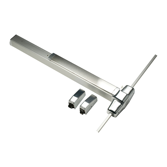
Surface Vertical Rod Exit Device
Devices covered by these instructions:
98/9927 Surface Vertical Rod Exit Device
98/9927-F (Fire) Surface Vertical Rod Exit Device
CD98/9927 (Cylinder Dogging) Surface Vertical Rod Exit Device
EL98/9927 (Electric Latch Retraction) Surface Vertical Rod Exit Device
Customer Service
1-877-671-7011
98/9927
Special tools needed:
5/64" hex wrench
#10-24 tap
Drill bits: #25, 1/8", 1/4",
• Screw chart ............................. 2
• Preparation chart .................... 3
• Device installation ............... 4-6
• Cut top rod ............................. 7
• Install rod extension ................ 7
• Optional equipment ............... 8
• Cut device .............................. 8
www.allegion.com/us
Installation Instructions
5/16", 13/32"
Index:
© Allegion 2016
Printed in U.S.A.
911375-00 Rev. 12/16-e
Advertisement
Table of Contents

Related Manuals for Von Duprin 98/9927


Summary of Contents for Von Duprin 98/9927
-
Page 1: Table Of Contents
Installation Instructions Devices covered by these instructions: 98/9927 Surface Vertical Rod Exit Device 98/9927-F (Fire) Surface Vertical Rod Exit Device CD98/9927 (Cylinder Dogging) Surface Vertical Rod Exit Device EL98/9927 (Electric Latch Retraction) Surface Vertical Rod Exit Device Special tools needed: 5/64”... -
Page 2: Screw Chart
SCREW CHART Surface mount or #10-24 X 1” Sex bolts (1-3/4” door) Sex bolts (2-1/4” door) #10-24 X 1-1/2” Surface mount (wood) #10 x 1-1/4” Wood screw - Packaged with trim - 990 trims (1-3/4” door) #10-24 X 1-3/8” 990 trims (2-1/4” door) #10-24 X 1-7/8”... -
Page 3: Preparation Chart
PREPARATION CHART Go to instructions on next page before using Preparation Chart #25 Drill #10-24 Tap 1/8” Drill 5/16” Drill (device side) pilot 1” deep 13/32” Drill (trim side) 13/32” Drill thru #25 Drill #10-24 Tap 1/8” Drill pilot 1” deep *Use rod guide as a template to mark holes... -
Page 4: Device Installation
Draw Horizontal Center Line ( ) and Assemble If Necessary, Remove NL Drive Screw Device Template NL drive screw Factory installed on Device back of center case template With the NL drive screw removed, key locks and unlocks lever, knob, or thumb piece. - Page 5 Install Trim (if using) and Secure Device Center Case Install Top Latch and Rod to Door 1¹⁄₂” Minimum clearance (with end cap removed) if device is too long for #325 sex door, see “Cut Device” latch bolts on back cover (required) Top rod (longer of...
- Page 6 Install Bottom Strike, Latch, and Rod Install Rod Guides and Covers Latch 248L-4 strike cover (2) *Rod guide (2) Install at midpoint of Shim (as needed each rod to engage latch) Bottom *See “Preparation #325 304L strike sexbolts Chart” on page 3 (required) Grout strike into floor...
-
Page 7: Cut Top Rod
CUT TOP ROD 1. Measure amount to cut off rod as shown below. 2. Cut rod. Note: Rod cutting is required for doors shorter than 7’. Amount Drive out to cut off roll pin 3. Drill new hole. 1/8” dia. drill thru Use cut off *84”... -
Page 8: Optional Equipment
OPTIONAL EQUIPMENT - CONTINUED CD (CYLINDER DOGGING) Std. mortise cylinder 1. Remove mortise cylinder cam and reinstall in reverse (Figure 1). 2. Insert key and rotate cam to install the cylinder to the cover plate (Figure 2). 3. Remove key to slide cover plate in position in the mechanism case. Offset toward pushbar Cylinder...
Need help?
Do you have a question about the 98/9927 and is the answer not in the manual?
Questions and answers