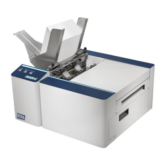
Rena MACH 5 Service Manual
Digital color printer
Hide thumbs
Also See for MACH 5:
- Operation manual (128 pages) ,
- Operator's manual (78 pages) ,
- Quick start manual (2 pages)
Table of Contents
Advertisement
Quick Links
Advertisement
Table of Contents
Troubleshooting

Related Manuals for Rena MACH 5


Summary of Contents for Rena MACH 5
-
Page 1: Service Guide
MACH 5, AS-950C, HJ950C DIGITAL COLOR PRINTER SERVICE GUIDE Rev 5-22-12... - Page 2 SAFETY PRECAUTIONS THIS EQUIPMENT PRESENTS NO PROBLEM WHEN USED PROPERLY. HOWEVER, CERTAIN SAFETY RULES SHOULD BE OBSERVED WHEN OPERATING THE RENA MACH 5 PRINTER. BEFORE USING THE PRINTER, YOU SHOULD READ THIS MANUAL CAREFULLY AND FOLLOW THE RECOMMENDED PROCEDURES, SAFETY WARNINGS, AND INSTRUCTIONS: ...
-
Page 3: Table Of Contents
TABLE OF CONTENTS Table of Contents Section 1 – Getting Acquainted SAFETY PRECAUTIONS Front View Rear View Print Engine Area Behind the Ink Tank Door Accessory Box Contents Control Panel Functions Printer Status Light Indicators Recommended Troubleshooting Supplies Common Service Tools Needed: Minimum Computer System Requirements Installing the Printer Software (Driver and Toolbox) Connecting the Digital Color Printer via Network (Ethernet Port) - Page 4 TABLE OF CONTENTS Clearing Media Jams How to Zero the Tilt Sensor SECTION 4 – Measurements and Adjustments Drive Belt Tension Adjustment Power Supply Media Sensors Feed Sensor Print Engine Sensors Feed Encoder Sensor and Encoder Wheel Print Engine Open Switch Dust Exhaust Fans Clutch (Feed Roller Drive) Feed Roller Drive Pulley Test:...
- Page 5 TABLE OF CONTENTS Cleaning/Replacing the Ink Revolvers Cleaning Pen Driver Printed Circuit Board Contacts Cleaning/Replacing the Service Station Removing the Service Station Cleaning the Service Station Replacing Wiper Roller Removing the Wiper Motor Assembly Replacing Service Station Lifting Arms Replacing the Clamshell Latch Pins Lower Clamshell Latch Pin Replacement Kit (42-900-30) Upper Clamshell Latch Pin Replacement Kit (42-900-35) Lubricating the Service Station...
- Page 6 TABLE OF CONTENTS NOTES ______________________________________________________ ______________________________________________________ ______________________________________________________ ______________________________________________________ ______________________________________________________ ______________________________________________________ ______________________________________________________ ______________________________________________________ ______________________________________________________ ______________________________________________________ ______________________________________________________ ______________________________________________________ ______________________________________________________ ______________________________________________________...
-
Page 7: Section 1 - Getting Acquainted
SECTION 3 OPERATING THE PRINTER Section 1 – Getting Acquainted SAFETY PRECAUTIONS THIS EQUIPMENT PRESENTS NO PROBLEM WHEN USED PROPERLY. HOWEVER, CERTAIN SAFETY RULES SHOULD BE OBSERVED WHEN OPERATING THE DIGITAL COLOR PRINTER. BEFORE USING THE PRINTER, YOU SHOULD READ THIS MANUAL CAREFULLY AND FOLLOW THE RECOMMENDED PROCEDURES, SAFETY WARNINGS, AND INSTRUCTIONS: ... -
Page 8: Front View
SECTION 3 OPERATING THE PRINTER Front View Exit Roller Cover – This cover plate must be removed to install the Service Station. Control Panel – Provides printer controls. See “Control Panel Functions” section. Side Guide Locking Knob – Used to secure the position of the side guide. Rear Media Support Guide –... -
Page 9: Rear View
SECTION 3 OPERATING THE PRINTER Rear View Main Power Switch, Receptacle and Fuse – Plug in AC power cord here. Switch turns main power on or off. Fuse provides over-current protection. Fuse rating: 2.5A, 250V, slow blow. CAUTION: Make sure power cord is disconnected from printer before checking/replacing fuse. WARNING: Press the ON/OFF Button, located on control panel, to properly shut-down the print engine. -
Page 10: Print Engine Area
SECTION 3 OPERATING THE PRINTER Print Engine Area Print Engine with printhead cartridge installed and printhead latch closed. Antistatic Brush Assembly – This assembly contains a conductive brush that is used to help reduce static energy and remove paper dust from the media. This assembly also contains upper pressure rollers and fingers that help guide the paper into the print engine. -
Page 11: Behind The Ink Tank Door
SECTION 3 OPERATING THE PRINTER Behind the Ink Tank Door Ink Tank Securing Latches – Used to hold the Ink Tanks in the slots. NOTE: Please be sure that both sides, at the bottom part of the latch, are engaged. Ink Tanks –... -
Page 12: Accessory Box Contents
SECTION 3 OPERATING THE PRINTER Accessory Box Contents Items contained in the Accessories Box The following items are included with your printer: Qty [Image Reference] Description [A] Ink Tanks - Cyan, Magenta, Yellow, Black, Black [B] Printhead Cartridge and packaging [C] Rear Media Support Guide - thumb screw attached to printer [D] Service Station... -
Page 13: Control Panel Functions
SECTION 3 OPERATING THE PRINTER Control Panel Functions BUTTON FUNCTION(s) Press to power-up or power-down the print engine. Note: The Main Power Switch must be ON, to power-up the print engine. Printer S/N 1000274898 and lower will automatically power-up after turning on the main power switch. - Page 14 SECTION 3 OPERATING THE PRINTER Printer Status Light Indicators Valid with Beta Firmware 110928_u or higher installed. The lights on the three buttons, shown below, indicate the status of the printer. LEGEND (For the Status Light Indicator chart on the next page.): Description ...
- Page 15 SECTION 1 GETTING ACQUAINTED Printer Status Light Indicator Chart (see legend) Valid with Beta Firmware 110928_u or higher installed. PAPER PAUSE Printer Status ON/OFF Additional Details, Possible Solution or Action RESUME CANCEL corresponding Toolbox message In this condition, it is safe to turn the Main Power Switch OFF or ON. ...
- Page 16 SECTION 1 GETTING ACQUAINTED Printer Status Light Indicator Chart (continued) (see legend) Valid with Beta Firmware 110928_u or higher installed. PAPER PAUSE Printer Status ON/OFF Additional Details, Possible Solution or Action RESUME CANCEL corresponding Toolbox message Press the RESUME button to continue printing. Job can also be resumed by clicking on the “Clear Error”...
- Page 17 SECTION 1 GETTING ACQUAINTED Printer Status Light Indicator Chart (continued) (see legend) Valid with Beta Firmware 110928_u or higher installed. PAPER PAUSE Printer Status ON/OFF Additional Details, Possible Solution or Action RESUME CANCEL corresponding Toolbox message Printer has detected that one of the media (PaperPath) sensors is blocked (interrupted).
- Page 18 SECTION 1 GETTING ACQUAINTED Printer Status Light Indicator Chart (continued) (see legend) Valid with Beta Firmware 110928_u or higher installed. PAPER PAUSE Printer Status ON/OFF Additional Details, Possible Solution or Action RESUME CANCEL corresponding Toolbox message Verify that printer is on a sturdy, level table (front to back and left to right).
-
Page 19: Recommended Troubleshooting Supplies
Parts Manual; when available. • Access to internet. Note: Part numbers, shown above (with “-N”), are for Neopost. Remove “-N” for Rena Systems. Add “-H” for Hasler. Common Service Tools Needed: This list is in addition to standard tools. •... - Page 20 SECTION 1 INSTALLATION How to check your system for the minimum system requirements, shown above: Right click on "My Computer" and select Properties. The system information, including Operating System, Processor Info and Memory info will be displayed under the "General" tab. How to check your system for the versions of "Microsoft .NET Framework”...
-
Page 21: Installing The Printer Software (Driver And Toolbox)
During this process the M Series Driver and M Series Toolbox utility will be installed onto your computer system. NOTE: If you are updating the Mach 5 (M Series) printer software (printer driver and toolbox utility); please be sure to Uninstall the old software before installing the new software. Use the “Uninstall”... - Page 22 SECTION 1 INSTALLATION 5. When the Printer Connections window opens. Select the USB choice and then click Next>. NOTE: If you plan to connect the printer to a Network; first you need to install via USB. After this process is complete; please refer to the section title “Connecting the Digital Color Printer via Network (Ethernet Port)”.
- Page 23 SECTION 1 INSTALLATION 9. When the “Finished software installation” window opens; uncheck the “Print Test Page” box. Since the printer still requires the installation of the ink tanks and the printhead cartridge; you do not want to print a test page at this time. Select if you want to set the printer as default or not.
-
Page 24: Connecting The Digital Color Printer Via Network (Ethernet Port)
INSTALLATION Connecting the Digital Color Printer via Network (Ethernet Port) Valid for printer models Mach 5, AS-950C and HJ950C; with firmware version 110928_u or higher installed. For printers with older firmware; please update the firmware and driver before proceeding. The following procedure is written for network systems that do not provide an automatic IP Address. In this case a static IP Address must be entered into the printer's "network status and configuration"... - Page 25 SECTION 1 INSTALLATION 5. Using a Cat5 network cable; connect the printer to your network via the Ethernet port. 6. Click on “Diagnostics”. The “Diagnostics” window will open; displaying a lot of information about the printer. This information will include the Network Status and configuration settings.
-
Page 26: Printer Driver Properties
Valid with driver version R9.1 or higher. The Printer Driver for the RENA Mach 5 works the same as any other Printer Driver for Windows. It does have some enhancements to help you maximize the ability of the Printer to print variable addressed pieces quickly and efficiently. -
Page 27: Layout Tab
SECTION 1 INSTALLATION • Media MEDIA TYPE MEDIA PROFILE Type: Chart at right lists the media profiles Plain Paper associated with the type of media chosen. Bright White Paper Plain Paper Sizes: Select for the given media that you are Transparency Film using. -
Page 28: Media Tab
SECTION 1 INSTALLATION • Watermark – Prints background text onto the media along with the original document. A few selections (SAMPLE, Draft, COPY, Confidential) are provided with the driver. First page only – When a watermark is selected; the “First page only” option is available. Selecting this option prints the watermark on the first page, but not subsequent pages. -
Page 29: Services Tab
SECTION 1 INSTALLATION Services Tab Services allows you to: • Print Configuration Page – Prints out the current configuration of the Printer including current Firmware Version, Network Connection, Printer Engine Serial Number and more. • Print Colorbar Page – Prints type and color bands to check print quality. -
Page 30: Printer Status Light Indicators
SECTION 1 INSTALLATION Using the Toolbox Utility Valid with firmware 110928_u. Once the M Series Printer Driver is installed you have access to the M Series Toolbox. The Toolbox lets you monitor ink usage, perform diagnostic checks, print reports and run maintenance tasks on the Printer from your computer. - Page 31 SECTION 1 INSTALLATION Cleaning Buttons: Provide 3 levels of cleaning for the Printhead Cartridge. These work the same way as the 3 Maintenance Level Buttons in the Printer Driver: Quick Clean Printhead – Circulates ink, wipes and cleans the Printhead Cartridge. Normal Clean Printhead –...
- Page 32 SECTION 1 INSTALLATION Mid Job Servicing – Allows user to adjust the frequency of printhead cleaning (servicing) during a print job. Based on the linear meters of media transported through the system. OFF = 32,000 meters (This distance is so large that it should never be reached) Level 1 = 500 meters Level 2 = 375 meters Level 3 = 250 meters...
- Page 33 SECTION 1 INSTALLATION [E] Firmware Download – This feature is used to update the main firmware in the printer. WARNING: This process should only be performed by a qualified support representative. In some cases firmware must be loaded using the “Firmware Migration Tool”.
-
Page 34: Diagnostics
SECTION 1 INSTALLATION Diagnostics From this screen you can see the current status of your Printer. You can also: Print Sample Page – Prints type and color bands to check print quality. Print Configuration Page – Shows the current configuration of the Printer including Firmware Version, Network Connection, Printer Serial Number and more. -
Page 35: Network Config
SECTION 1 INSTALLATION Network Config Permits you to view, enter or change settings to connect the Printer to your network. Network Connection Set Up: This is a brief description of the processes. For more details see: “Connecting the Digital Color Printer via Network (Ethernet Port)”... -
Page 36: Service Menu
SECTION 1 INSTALLATION Service Menu For authorized personnel only (password protected). Provides access to more advanced Printer Control and Maintenance menus. Enter password to view the Service menus. Firmware 110928_? and higher PW = 630 Firmware 110513_? and lower PW = servicepw Once you gain access to the Service Menu, you will notice that several new menu options become available: “Printer Maint Config,”... - Page 37 SECTION 1 INSTALLATION Printout Control The following settings will vary from unit to unit. The unit value (measurement) used in the following features is microns (1000 units = 1mm). NOTE: You must press Submit for the change to take effect in the printer. •...
- Page 38 SECTION 1 INSTALLATION • Print Color Bars Page: Prints 7 solid blocks of color bars to show how well the Printhead is mixing colors and printing. Prints four blocks of mixed color (black, red, green, purple) along with three blocks representing the cyan, magenta, and yellow ink channels. Commands Help Screen: Provides a list of available EWS service commands.
-
Page 39: Section 2 - Installation
SECTION 1 INSTALLATION Section 2 – Installation This section provides a few of the critical installation items. Please refer to the “Operator’s Guide” for complete Installation and Operation instructions. Tools Needed for Installation • Knife and scissors to open packaging •... -
Page 40: Installing The Service Station
SECTION 1 INSTALLATION 3. Pull up on the two tabs to remove the cardboard Transport Tab from the Service Station. 4. Carefully close and relatch the Upper Print Engine. Then close the Top Cover. Installing the Service Station Note: New printers are shipped with the Service Station pre-installed. In this case all you need to do is remove the cardboard shipping insert as described above. - Page 41 SECTION 1 INSTALLATION 5. Carefully remove the Service Station from its packaging. NOTE: Loose parts may fall out. Keep wiper roller side facing up, when removing the packaging. CAUTION! Make sure latches on the Wiper Roller are fully latched before installing the Service Station. Check the latch at each end of the wiper roller.
- Page 42 SECTION 1 INSTALLATION 8. Once the Ribbon Cable is properly connected to the Service Station Circuit Board; gently slide the Service Station, wiper roller end first, into the Service Station Slot until it stops. The Service Station fits into the slot immediately above the Ink Tank slots. NOTE: The Ink Tank Door must be open to perform this procedure.
- Page 43 SECTION 1 INSTALLATION 10. GENTLY push in on the Service Station with one hand, while slowly turning the “Large Gear” clockwise with the other hand. It should be easy to turn this gear and the service station should start to drive into the print engine squarely.
-
Page 44: Install The Ink Tanks
SECTION 1 INSTALLATION Install the Ink Tanks The Digital Color Printer uses five Ink Tanks (two Black, one Cyan, one Magenta, and one Yellow). The Ink Tank is a delicate, precision device. Handle with extreme care to avoid damage. Ink Tank Anatomy The ink used in this system may be harmful if swallowed. -
Page 45: Procedure (Installing The Ink Tanks)
SECTION 1 INSTALLATION Procedure (Installing the Ink Tanks): This procedure assumes that you are installing Ink Tanks into a printer that doesn’t have any Ink Tanks installed. If you are replacing an empty Ink Tank, please refer to the “Replacing the Ink Tanks” section. 1. - Page 46 SECTION 1 INSTALLATION Ink Tank firmly. Then pull the Ink Tank back out about an inch. Then push the Ink Tank back in, firmly. 7. Close and lock all three Ink Tank Securing Latches. IMPORTANT: Make sure both sides of the Latch are engaged at the bottom. 8.
-
Page 47: Installing The Printhead Cartridge
SECTION 1 INSTALLATION Installing the Printhead Cartridge The Digital Color Printer uses a single Memjet® printhead cartridge. The Printhead Cartridge is a delicate, precision device. Handle with extreme care to avoid damage and issues that could degrade print quality. Printhead Cartridge Protective Packaging NOTE: Discard protective tape once it is removed. - Page 48 SECTION 1 INSTALLATION CAUTION! • Use electrostatic discharge (ESD) handling precautions. • Hold the Printhead Cartridge by the handles ONLY. • DO NOT touch the ink couplings, nozzle surface or electrical contacts. • DO NOT unpack the Printhead Cartridge until the Printer is ready for installation.
-
Page 49: Procedure (Installing The Printhead)
SECTION 1 INSTALLATION Procedure (Installing the Printhead): This procedure assumes that you are installing a Printhead Cartridge into a printer that does NOT have a Printhead Cartridge installed. If your printer already has a Printhead Cartridge installed, and you wish to replace the Printhead Cartridge;... - Page 50 SECTION 1 INSTALLATION 6. Prepare the printhead cartridge. Carefully remove the Printhead Cartridge from the foil vacuum packaging. Tear at notch or cut end with scissors. CAUTION: DO NOT touch the ink couplings, printhead nozzle surface or electrical contacts. [A] Remove the protective plastic cover. Hold the Printhead cartridge by the handle.
- Page 51 SECTION 1 INSTALLATION 7. Carefully insert the printhead cartridge into the compartment at an angle, with the print nozzle surface facing down and the ink receptacles facing towards the Ink Couplings and Fig A hoses; as shown [Fig A]. 8. Once the cartridge is fully inserted, gently but firmly rotate the top of the cartridge to a vertical position;...
- Page 52 SECTION 1 INSTALLATION 11. Slowly close the Printhead Latch until it locks. It will be resistant, but apply consistent pressure and the ink couplings will ease into the ink ports on the printhead. Once latch is closed, the printer will automatically start running a “printhead priming routine”.
- Page 53 SECTION 1 INSTALLATION 12. Once the printhead priming process is successful (all ink tubes are filled, in and out of the printhead); it will take an additional 5 - 10 minutes for the printer to complete the process. During this time the printer will emit a number of chirps, whirrs and other noises.
-
Page 54: Section 3 - Troubleshooting
SECTION 3 TROUBLESHOOTING SECTION 3 – Troubleshooting The following troubleshooting guides are provided to assist you in solving any problems that might occur with the Digital Color Printer. We have tried to make them as complete as possible, but this section will always be evolving. -
Page 55: Examples Of Print Quality Issues (Including Possible Causes And Solutions)
SECTION 3 TROUBLESHOOTING Examples of Print Quality Issues (including possible causes and solutions) The Memjet printhead cartridge contains over 70,000 inkjet nozzles. These nozzles are divided into ten rows; two rows of nozzles for each color channel. Due to the high number of nozzles; it is not uncommon for some nozzles to become contaminated or clogged. - Page 56 SECTION 3 TROUBLESHOOTING Clogged Nozzles: Clogged/dehydrated nozzles will normally show as thin, crisp, vertical lines of missing color. Multiple adjacent clogged nozzles will show as wider, crisp, vertical lines of missing color. Clogged nozzles are normally due to Printhead nozzle dehydration or partial contamination. Possible Solutions: •...
- Page 57 SECTION 3 TROUBLESHOOTING Color Mixing Issues: Color mixing will show as muddy, mottled or distorted (grainy) colors. Color mixing occurs when the ink from one color channel crosses over into another color channel. Since the inkjet nozzle rows are located very close to one another (ten rows of ~7,000 nozzles, located within a 0.8 mm space), it is easy for partials or fibers to create bridges across color channels.
-
Page 58: The Printhead Cartridge
SECTION 3 TROUBLESHOOTING The Printhead Cartridge The Memjet printhead cartridge contains over 70,000 inkjet nozzles. These nozzles are divided into ten rows; two rows of nozzles for each color channel. Due to the high number of nozzles; it is not uncommon for some nozzles to become contaminated or clogged. - Page 59 SECTION 3 TROUBLESHOOTING The Printhead Cartridge (continued) CONDITION PROBLEM SOLUTION System will not prime the Printhead nozzles dry (air pulled Wet the Printhead nozzles printhead after installing through nozzles; not allowing using distilled water and a system to create vacuum) wet, lint-free cloth.
-
Page 60: The Printer
SECTION 3 TROUBLESHOOTING The Printer Service Tip: If you recently replaced the Main Board, please see “Replacing the Main PC Board (MPCA)” and “MPCA (Main Printed Circuit Assembly) Connections”; to verify your connections. Also check for damaged wires and loose connections. NOTE: The printer will not print if any of the five ink tanks are empty or missing. -
Page 61: Service Station Problems
SECTION 3 TROUBLESHOOTING Service Station Problems CONDITION PROBLEM SOLUTION Service Station Drive Service Station was not installed Eject Service Station. Cycle print Motor stalls. properly. engine off/on. If drive motor turns Wiper roller securing latches are without stalling then motor is OK. not closed;... -
Page 62: Interface Communication Problems
SECTION 3 TROUBLESHOOTING Interface Communication Problems CONDITION PROBLEM SOLUTION M Series Driver does not Wrong USB port selected in “M Verify that you are selecting the respond to printer being Series Driver”. appropriate USB port in the driver Ports Tab. Note: During connected via USB. -
Page 63: Feeding Problems
SECTION 3 TROUBLESHOOTING Feeding Problems CONDITION PROBLEM SOLUTION Intermittent feeding Media Support Wedge not used. The Media Support Wedge adds a slope to the stack and helps feeding. Side Guides set too tight to media. Readjust Side Guides. Dirty Feed Rollers. Clean the Feed Roller with distilled water and a cloth. -
Page 64: Error's And Warnings
SECTION 3 TROUBLESHOOTING Error’s and Warnings Control Panel Light Sequences See Section titled “Printer Status Light Indicators”. Alert Window Messages Messages sent from the driver and displayed on PC screen in a small popup window. MESSAGE SOLUTION …. Ink Low Reorder Ink Example: Black Ink Low Reorder Ink... -
Page 65: Toolbox System Status Messages
SECTION 3 TROUBLESHOOTING Toolbox System Status Messages Displayed, in red, in the M Series Toolbox utility. SYSTEM STATUS PROBLEM SOLUTION PAPERPATH_FEED_TIME Out of Paper Load media into printer and press the PAPER/RESUME button. No media is reaching the If media is present; check/adjust the print engine. - Page 66 SECTION 3 TROUBLESHOOTING [Fatal 71 02-? offline Possible problem with Check for mechanical bind in Service cancelpage] drive, movement or Station movement or lifting arm position sensing of the: See additional information movement. shown in Toolbox. Check Service Station positioning and Reason: Lifting Arm positioning sensors.
-
Page 67: Ink Accumulating In The Wrong Areas Of The Printer
SECTION 3 TROUBLESHOOTING Toolbox System Status Messages (continued) SYSTEM STATUS PROBLEM SOLUTION MECH_CANCELPAGE Job was canceled by Wait until print job has cleared from user pressing the printer. Then manually clear job from CANCEL button. computer’s print queue. Then send new print job. -
Page 68: Clearing Media Jams
SECTION 3 TROUBLESHOOTING Clearing Media Jams When the printer detects a media jam, it will stop automatically. The control panel PAPER/RESUME and PAUSE/CANCEL lights will blink simultaneously. The message “PAPERPATH_PRINTZONE_BLOCKED” or “PAPERPATH_PAPERJAM” will be displayed in the Toolbox. Once the jam has been removed from the system and the print engine is closed; press the PAPER/RESUME button to continue printing. -
Page 69: How To Zero The Tilt Sensor
SECTION 3 TROUBLESHOOTING Misfeeds Misfeeds can be corrected by readjusting the Sheet Separators to the media or replacing them. See “Replacing the Sheet Separators”. How to Zero the Tilt Sensor CAUTION! Prior to using this option, verify that your printer is on a sturdy, level surface. This is of utmost importance, since being out of level can cause the printer to perform poorly. -
Page 70: Section 4 - Measurements And Adjustments
SECTION 4 ADJUSTMENT SECTION 4 – Measurements and Adjustments CAUTION ALWAYS WEAR A WRIST STRAP THAT IS GROUNDED WHEN TOUCHING ELECTRONIC DEVICES. Drive Belt Tension Adjustment REQUIREMENT: To ensure the Drive Belt has the proper tension, use the 42-101-33T Belt Tension Tool to properly adjust Motor Belt Drive tension without guesswork. -
Page 71: Power Supply
SECTION 4 MAINTENANCE Power Supply The Power supply converts the incoming AC voltage into 24 VDC. The DC output provides power to the electronics for the entire printer. Power Supply Measurements: Input: 100 – 240 VAC (This is an auto-switching power supply) Output: 24 VDC (+ or –... -
Page 72: Media Sensors
SECTION 4 ADJUSTMENT Media Sensors Feed Sensor The feed sensor detects the media as it feeds between the sheet separation area and the print engine. This is a retro-reflective sensor. The sensor is located below the deck of the printer (see image below). The sensor looks up at a reflector, which is attached to the underside of the plate on the center pressure rollers. -
Page 73: Print Engine Sensors
SECTION 4 MAINTENANCE Print Engine Sensors There are two media sensors within the feed path of the print engine that are used to monitor paper entering and exiting the print engine area. There is also a Margin sensor in the paper feed path, but this sensor is not active (not used). Entry Sensor Receiver Mark Sensor... -
Page 74: Feed Encoder Sensor And Encoder Wheel
SECTION 4 ADJUSTMENT Feed Encoder Sensor and Encoder Wheel The Feed Encoder is responsible for matching the speed of the feed section with the speed of the print engine. If a problem develops with this sensor (example: encoder wheel gets dirty), then you will normally see issues with the transition of media from the feed section to the print engine. -
Page 75: Print Engine Open Switch
SECTION 4 MAINTENANCE Print Engine Open Switch The Print Engine Open Switch is activated by the Print Engine Latch on the non-operator side. When the latch is released, to open the top section of the Print Engine, the switch position is toggled. Note: This switch is not on early printer models. -
Page 76: Clutch (Feed Roller Drive)
SECTION 4 ADJUSTMENT Clutch (Feed Roller Drive) The clutch is used to engage/disengage drive to the feed rollers. When the feed motor is driving and the clutch is engaged; the feed rollers are driven to deliver media into the print engine. Measurement: To check the clutch for proper operation: Measure from TP3 to the bottom pin on J8 (Clutch Out), on... -
Page 77: Dual Pinch Valve Connection
SECTION 4 MAINTENANCE Dual Pinch Valve Connection If you should receive the [System Status: Fatal 71 02-? offline cancelpage] message in the Toolbox utility window; along with the message “Reason: ids valve failed three times” the printer has detected a problem with the Dual Pinch Valve. It is possible that the Dual Pinch Valve’s Printed Circuit Assembly connector may be loose or disconnected. - Page 78 SECTION 4 ADJUSTMENT 3. Look through the open side of the Printer. The Dual Pinch Valve connector (white) is located just behind the metal duct, for the lower dust exhaust fan. 4. Use a long-blade flat-tip screwdriver to carefully reach across the print engine and push in or reconnect the small white PCA connector.
-
Page 79: Interface Board Test Points
SECTION 4 MAINTENANCE Interface Board Test Points This board is located on the non-operator side of the printer GND: Logic Ground Connect your ground lead here for all measurements except TP3 (clutch). 12VDC: Power In Improperly tagged; should be 24VDC. Hopefully this will be corrected in a future revision. TP2: Counter 3 VDC open (no paper);... -
Page 80: Section 5 - Disassembly/Assembly Procedures
Installation and Service Videos (where to find) Installation and Service Videos are also available for this product. Neopost/Hasler Technicians: Please see the Knowledgebase or NeoU for Installation and Service Videos. Rena Systems Technicians: Please see the Rena Dealer Net area for Installation and Service Videos. -
Page 81: Basic Disassembly
SECTION 5 DISASSEMBLY AND ASSEMBLY Basic Disassembly Turn off Power Disconnect Power Cord Disconnect Interface Cable Service Disassembly Procedures WARNING! THE FOLLOWING DISASSEMBLY SHOULD ONLY BE DONE BY A QUALIFIED, TRAINED SERVICE REPRESENTATIVE. WARNING! ALWAYS POWER DOWN THE PRINTER BEFORE CONNECTING OR DISCONNECTING ANY WIRING HARNESSES OR CABLE CONNECTIONS TO AVOID SERIOUS SHOCK OR INJURY. -
Page 82: Left-Hand Side Covers
SECTION 5 DISASSEMBLY AND ASSEMBLY Left-hand Side Covers Remove (2) screws at the top and bottom of the Left- hand Rear Side Cover. Remove the Cover. 2. Remove (2) screws at the top and bottom of the Left- hand Front Side Cover. Pull Cover away from machine and set aside. -
Page 83: Right-Hand Side Cover
SECTION 5 DISASSEMBLY AND ASSEMBLY Right-hand Side Cover 1. Remove the (2) screws at the top of the Cover. Then remove the (3) screws from the bottom of the Cover. Major Components under Right-Hand Side Cover 1. Main PC Board 2. -
Page 84: Replacing Motor Drive Belt Or Motor
SECTION 5 DISASSEMBLY AND ASSEMBLY Replacing Motor Drive Belt or Motor 1. Remove Right-hand Side Cover. NOTE: To remove the motor, remove the five screws holding the right-hand side cover. 2. [1] Loosen the (2) motor mounting screws to relieve tension on the Motor Drive Belt. [2] Then remove the (2) screws ] and the Encoder Sensor. -
Page 85: Replacing The Feeder Encoder And/Or Encoder Sensor
SECTION 5 DISASSEMBLY AND ASSEMBLY 3. Push the Clutch toward the pulley to get access to the mounting pin. Remove the retaining pin. 4. Remove the Clutch from the Feed Roller Shaft. 5. Reassemble in reverse order. Replacing the Feeder Encoder and/or Encoder Sensor 1. -
Page 86: Replacing Feed Rollers
SECTION 5 DISASSEMBLY AND ASSEMBLY Replacing Feed Rollers 1. Unplug the Printer from power. 2. Follow the instructions above and remove the Right- hand Side Cover, Drive Belt and Clutch before beginning the replacement of the Feed and Forwarding Rollers. 3. - Page 87 SECTION 5 DISASSEMBLY AND ASSEMBLY 8. Lift the Center Plate Assembly from the machine and set aside. 9. Remove the screw holding the Clutch Support Bracket and remove the bracket. 10. Remove the Rear Feed Roller Drive Pulley. NOTE: The spring and washer keep tension on the clutch so that the pin holding the clutch remains in place.
- Page 88 SECTION 5 DISASSEMBLY AND ASSEMBLY 11. Remove the washer and spring from the Feed Roller Shaft. NOTE: The spring and washer keep tension on the clutch so that the pin holding the clutch remains in place. Reassemble these parts as shown. 12.
-
Page 89: Replacing Delivery Rollers
SECTION 5 DISASSEMBLY AND ASSEMBLY Replacing Delivery Rollers The Delivery Rollers are part of the Front Center Assembly on the feed end of the Print Engine. 1. Remove the Left hand Rear Side Cover. Remove (2) screws at the top and bottom of the Rear Left- hand Side Cover. - Page 90 SECTION 5 DISASSEMBLY AND ASSEMBLY 4. Remove Top Cover. Remove mounting screw on left-hand side (Control Panel Side). Remove Top Cover and set aside. 5. Remove Antistatic Brush Assembly [A] from mounting studs. Unlatch the two latches (one on either side of the Assembly) and lift the assembly off the four mounting pins as shown.
- Page 91 SECTION 5 DISASSEMBLY AND ASSEMBLY Remove Ink Station Door. Carefully unhook the (2) springs (one on each side), then remove the mounting screw from the left-hand side (Control Panel Side). Remove Door and set aside. 8. Remove Left hand Inner Side Frame (3 screws).
- Page 92 SECTION 5 DISASSEMBLY AND ASSEMBLY 10. Remove Side Fan (2 screws). [A] Remove Media Bracket Stud #1 (1 screw) and the small screw holding the Assembly on left-hand side. [B] Take the Front Center Plate by sliding it off the alignment studs on the Print Engine.
-
Page 93: Replacing Interface Pc Board
SECTION 5 DISASSEMBLY AND ASSEMBLY Replacing Interface PC Board 1. Remove the Right hand Side Cover. 2. Unplug the PC Board power cord [1] from the Power Inlet on the PC Board. 3. Unplug (9) Connectors for Clutch, Sensors, Motor, Encoder and Counter wires. -
Page 94: Replacing The Main Pc Board (Mpca)
SECTION 5 DISASSEMBLY AND ASSEMBLY Replacing the Main PC Board (MPCA) Valid for Z3 and Z4 Print Engines. WARNING THE FOLLOWING PROCEDURE SHOULD ONLY BE DONE BY A QUALIFIED, TRAINED SERVICE REPRESENTATIVE. Before you Begin: Verify that you have ordered and received the proper version board for the Print Engine that is installed, in your printer. - Page 95 SECTION 5 DISASSEMBLY AND ASSEMBLY Procedure: 1. Turn off the Printer CAUTION WHENEVER POWERING DOWN UNIT, ALWAYS: 1. PRESS THE POWER BUTTON ON THE CONTROL PANEL. 2. WAIT FOR THE PRINTER TO STOP PROCESSING. 3. THEN PRESS THE MAIN POWER SWITCH ON THE REAR PANEL. 2.
- Page 96 SECTION 5 DISASSEMBLY AND ASSEMBLY 7. Remove the Main PCB Cover Using a T10 Torx driver remove the screws that secure the cover. There will be 4 or 5 screws, depending on print-engine version. Tip: The top section of this cover wraps around the back- side of the enclosure.
- Page 97 SECTION 5 DISASSEMBLY AND ASSEMBLY 11. Install the New Main PCB to the frame using the T10 screws. 12. Carefully reconnect all connections to the New Main PCB, in the following order. Please follow this process, step by step, to be sure each connection is installed into the appropriate socket.
- Page 98 SECTION 5 DISASSEMBLY AND ASSEMBLY a. J1002 Cable J1002 Socket Location (Connection)
- Page 99 SECTION 5 DISASSEMBLY AND ASSEMBLY b. J1000 Cable J1000 Socket Location (Connection)
- Page 100 SECTION 5 DISASSEMBLY AND ASSEMBLY c. J551 Cable J551 Socket Location (Connection)
- Page 101 SECTION 5 DISASSEMBLY AND ASSEMBLY d. J703 Cable J703 Socket Location (Connection)
- Page 102 SECTION 5 DISASSEMBLY AND ASSEMBLY e. P2002 Cable P2002 Socket Location (Connection)
- Page 103 SECTION 5 DISASSEMBLY AND ASSEMBLY f. P2004 Cable P2004 Socket Location (Connection)
- Page 104 SECTION 5 DISASSEMBLY AND ASSEMBLY g. P2006 Cable P2006 Socket Location (Connection)
- Page 105 SECTION 5 DISASSEMBLY AND ASSEMBLY h. J35 Cable J35 Socket Location (Connection)
- Page 106 SECTION 5 DISASSEMBLY AND ASSEMBLY i. 50014 Cable 50014 Socket Location (Connection)
- Page 107 SECTION 5 DISASSEMBLY AND ASSEMBLY j. P2005 Cable P2005 Socket Location (Connection)
- Page 108 SECTION 5 DISASSEMBLY AND ASSEMBLY k. P2003 Cable P2003 Socket Location (Connection)
- Page 109 SECTION 5 DISASSEMBLY AND ASSEMBLY l. J20 Cable J20 Socket Location (Connection)
- Page 110 SECTION 5 DISASSEMBLY AND ASSEMBLY m. J2001 Cable J2001 Socket Location (Connection)
- Page 111 SECTION 5 DISASSEMBLY AND ASSEMBLY n. J250 Data Cable J250 Data Cable Socket Location (Connection) o. J260 Data Cable J260 Data Cable Socket Location (Connection)
- Page 112 SECTION 5 DISASSEMBLY AND ASSEMBLY 13. Verify that All Cables Are Installed NOTE: There will be 10 open sockets after all cables have been installed. Open Sockets: J550, J554, J553, J750, J706, J504, J353, J400, J37, P900.
- Page 113 SECTION 5 DISASSEMBLY AND ASSEMBLY 14. Reinstall the Main PCB Cover with 4 or 5 screws removed in Step 7. Do NOT over-tighten the screws. Be careful not to pinch any wires. Tip: Triple check that all connections have been properly made before installing the Main PCB Cover.
-
Page 114: Mpca (Main Printed Circuit Assembly) Connections
SECTION 5 DISASSEMBLY AND ASSEMBLY MPCA (Main Printed Circuit Assembly) Connections Valid for Z3 and Z4 Print Engines only. The following chart shows where the connections to the MPCA come from and a brief description of what they are used for (what they do). LABEL COMING FROM DESCRIPTION... -
Page 115: Removing The Print Engine
SECTION 5 DISASSEMBLY AND ASSEMBLY Removing the Print Engine 1. Open the Top Cover. Open the Toolbox, press the Release Printhead button. Printer will "deprime" pumping all the ink back to the ink tanks, then the Printhead Cover will open. Remove the Printhead Cartridge and carefully put it back in the original packaging. - Page 116 SECTION 5 DISASSEMBLY AND ASSEMBLY Remove Ink Station Door. Carefully unhook the (2) springs (one each side), then remove the mounting screw from the left-hand side (Control Panel Side). Remove Door and set aside. 7. Remove Top Cover. Remove (2) Screws (one each side).
- Page 117 SECTION 5 DISASSEMBLY AND ASSEMBLY Unplug Network, USB and Main Power connectors from Print Engine Circuit Board. Disconnect the wires attached to the Power, Paper and Cancel Buttons at connectors. NOTE: Wires are labeled to simplify reconnection. 10. Remove Antistatic Brush Assembly [A] from mounting studs.
- Page 118 SECTION 5 DISASSEMBLY AND ASSEMBLY 11. Disconnect the following wires from the Interface Printed Circuit Board located on the right hand side of the Printer Frame.: [A] Clutch Out (J8), [B] S4 (J9) [C] Motor In (J2) [D] Disconnect the Encoder wire from the Encoder Printed Circuit Board.
- Page 119 SECTION 5 DISASSEMBLY AND ASSEMBLY 13. Raise the Printer up on blocks so you can reach underneath to access and remove the (4) screws holding the bottom of the Print Engine to the Base Plate. 14. Carefully slide Print Engine out of Printer.
-
Page 120: Print Engine Basic Disassembly
SECTION 5 DISASSEMBLY AND ASSEMBLY Print Engine Basic Disassembly The Print Engine must be removed from the Printer for these procedures. See "Removing the Print Engine" in previous pages. It is also assumed that the ink tanks, printhead and service station are removed. Removing the Print Engine Base Provides access to parts located underneath the Print Engine. -
Page 121: Replacing Peristaltic Pump Assembly
SECTION 5 DISASSEMBLY AND ASSEMBLY Replacing Peristaltic Pump Assembly Remove old Pump Assembly: [A] Remove (4) screws that hold bracket to chassis. [B] Cut cable tie holding wiring harness to Assembly. [C] Unplug connector from pump motor circuit board. [D] Cut as shown or remove hoses from barbs. -
Page 122: Replacing Dpca Board
SECTION 5 DISASSEMBLY AND ASSEMBLY Replacing DPCA Board [A] Remove (2) screws on the outside of the chassis that attach the Circuit Board Bracket to chassis. [B] Carefully move the DPCA Assembly out to unplug the wire harness connectors. NOTE: Make sure you know which connectors go with which socket. -
Page 123: Replacing Buffer Boxes (3 Per Machine)
SECTION 5 DISASSEMBLY AND ASSEMBLY Replacing Buffer Boxes (3 per machine) [A] Each Buffer Box is held in place by (2) screws accessed through the ink tank station. Using a long Phillips screwdriver, remove the screws and pull up on the Box to remove it from the chassis. -
Page 124: Removing The Pen Driver Printed Circuit Assembly (Pca)
SECTION 5 DISASSEMBLY AND ASSEMBLY Removing the Pen Driver Printed Circuit Assembly (PCA) Location: Upper Clamshell next to the Printhead Cartridge Bay. [A] Remove the Pen Driver PCA Cover (lightly glued in place). [B] Disconnect the (2) Ethernet data cables, then unplug the power connector and Main PCA harness connectors. -
Page 125: Replacing The Ink Tank Latches
SECTION 5 DISASSEMBLY AND ASSEMBLY Internal: [A] Remove the Pen Driver Printed Circuit Board Cover. [B] Remove (2) screws from bottom of Pen Driver Printed Circuit Board Bay. [C] Locate and carefully release the (2) black locking tabs holding the Starwheel Assembly to the metal bracket. -
Page 126: Removing The Main Printed Circuit Assembly (Mpca) Cover
SECTION 5 DISASSEMBLY AND ASSEMBLY Removing the Main Printed Circuit Assembly (MPCA) Cover To get access to parts on the Print Engine clamshell, the MPCA Panel Cover must be removed and the panel folded out of the way. 1. Remove (4) screws to remove the Cover. -
Page 127: Replacing Encoder Or Encoder Sensor
SECTION 5 DISASSEMBLY AND ASSEMBLY Replacing Encoder or Encoder Sensor Printers with Z3/Z4 Print Engines have an enclosed Encoder Assembly (see picture at below). [A] Remove (3) screws holding Encoder Cover in place. [B] Unplug the wire harness from the Encoder Sensor. -
Page 128: Replacing Paper Path Motor Or Drive Belt
SECTION 5 DISASSEMBLY AND ASSEMBLY Replacing Paper Path Motor or Drive Belt [A] Remove (2) screws that attach the Motor Assembly to the lower Print Engine Clamshell. Pull the Motor straight out so the Motor Pulley clears the drive belt. NOTE: If removing Motor, unplug the two wire connectors. -
Page 129: Replacing Belt Drive Gear Pulleys
SECTION 5 DISASSEMBLY AND ASSEMBLY Replacing Belt Drive Gear Pulleys There are three. One is mounted on the Exit Grit Roller Shaft, one is located behind the Encoder Assembly on another Grit Roller Shaft and one is mounted on the Entry Grit Roller Shaft. First, you may need to loosen or remove the Drive Belt, see "Replacing the Paper Path Motor or Drive Belt". -
Page 130: Replacing Lifter Motor Assembly Or Lifter Gear
SECTION 5 DISASSEMBLY AND ASSEMBLY Replacing Lifter Motor Assembly or Lifter Gear Remove Lifter Motor Assembly Only: [A] Unplug the wire harness from the Lifter Motor Assembly. [B] Remove the (2) screws holding the Motor Assembly to the Motor Assembly Bracket. [C] Gently remove the Motor Assembly. -
Page 131: Replacing Stepper Motor
SECTION 5 DISASSEMBLY AND ASSEMBLY Replacing Stepper Motor [A] Remove (2) screws. [B] Unplug the wire harness from the Stepper Motor printed circuit board. [C] Note the position of the motor gears to make sure gears will mesh with the Service Station gear (if Service Station is installed.) Install in reverse order. - Page 132 SECTION 5 DISASSEMBLY AND ASSEMBLY Lubricating the Grit Roller Ground Clips Three Ground clips are located on the right side of the Print Engine, at the ends of the Grit Roller Shafts. To access them you must remove the Lifter Motor and Stepper Motor. See Replacing Lifter Motor and Replacing Stepper Motor on the previous two pages.
-
Page 133: Removing The Clamshell Assembly
SECTION 5 DISASSEMBLY AND ASSEMBLY Removing the Clamshell Assembly Provides access to parts under the Clamshell Assembly. 1. Remove the (4) screws attaching the clamshell to the chassis (1 at each corner). 2. Gently lift the Clamshell Assembly from the chassis –... -
Page 134: Replacing Paperpath Entry Sensor
SECTION 5 DISASSEMBLY AND ASSEMBLY Replacing Paperpath Entry Sensor The Paperpath Entry Sensor consists of a Receiver located in the upper Clamshell and an Emitter located in the lower Clamshell. Receiver (Under Upper Clamshell): [A] Remove (2) screws. [B] Disconnect wiring harness. Install in reverse order. -
Page 135: Replacing Service Station Sled Printed Circuit Boards
SECTION 5 DISASSEMBLY AND ASSEMBLY Replacing Service Station Sled Printed Circuit Boards [A] Remove (2) screws. [B]. Carefully disconnect the (2) connectors. [C] Swing Sled away from Clamshell and turn over. Carefully unclip the two printed circuit boards. Install reverse order. NOTE: Make sure wire harnesses are plugged into correct printed circuit board. -
Page 136: Reinstall Main Printed Circuit Board Assembly
SECTION 5 DISASSEMBLY AND ASSEMBLY Reinstall Main Printed Circuit Board Assembly 1. Gently lift up the Wiring Panel. NOTE: DO NOT pinch or cut wires running through Frame. 2. Reinstall the two (2) mounting screws into bottom of MPCA Panel. 3. -
Page 137: Section 6 - Service Maintenance
SECTION 6 MAINTENANCE Section 6 – Service Maintenance General, periodic maintenance is needed to keep the Printer in good working order. Many tasks can be performed by operators with basic supplies, no special tools needed. Other tasks should only be performed by trained service personnel. -
Page 138: Replacing The Ink Tanks
SECTION 6 MAINTENANCE WARNING! ALWAYS POWER DOWN THE PRINTER BEFORE CONNECTING OR DISCONNECTING ANY WIRING HARNESSES OR CABLE CONNECTIONS TO AVOID SERIOUS SHOCK OR INJURY. CAUTION • ALWAYS USE APPROPRIATE PERSONAL PROTECTION EQUIPMENT (PPE). • USE ELECTROSTATIC DISCHARGE (ESD) PROTECTION WHEN MAINTAINING EQUIPMENT. •... -
Page 139: Cleaning/Replacing The Printhead Cartridge
Cleaning/Replacing the Printhead Cartridge Cleaning The Printhead Cartridge in the RENA Mach 5 Printer is cleaned automatically each time the machine is turned on or when the Level 1 Maintenance routine is performed by the operator. This can be found under the Service Tab, Level 1 Maintenance in the Printer Driver or the User Maintenance Levels in the Printer Toolbox. -
Page 140: Replacing The Printhead Cartridge
SECTION 6 MAINTENANCE Replacing the Printhead Cartridge 1. Open the M Series Toolbox. Go to All Programs, open the Printer Systems Folder and open the Toolbox. On the opening screen you will see System Status information in the upper left corner. 2. -
Page 141: Cleaning/Replacing The Ink Revolvers
SECTION 6 MAINTENANCE Cleaning/Replacing the Ink Revolvers First Deprime the system and remove the Printhead Cartridge. New Ink Revolver includes attached leader hoses and hose connectors. 1. Remove cover by squeezing sides to release the tabs. Remove cover and set aside. NOTE: Cover does not have to be removed to clean Ink Revolver Couplings. - Page 142 SECTION 6 MAINTENANCE 3. Once all the hoses have been connected to the new Ink Revolver, remove the C-Clip from the hinge pin holding the Ink Revolver. Remove the Pin. 4. Slide the old Ink Revolver forward in its track and remove.
-
Page 143: Cleaning Pen Driver Printed Circuit Board Contacts
SECTION 6 MAINTENANCE Cleaning Pen Driver Printed Circuit Board Contacts Clean the Printed Circuit Board contact pins that connect with the Printhead Cartridge. 1. Remove the Printhead Cartridge. Locate the contact pins along the base of the Pen Driver Printed Circuit Board. -
Page 144: Cleaning/Replacing The Service Station
SECTION 6 MAINTENANCE Cleaning/Replacing the Service Station The Service Station cleans the Printhead Cartridge of excess ink and debris, keeps the Printhead hydrated and protected when not in use, captures ink used to keep nozzles clear, and acts as a base to support media during printing. - Page 145 SECTION 6 MAINTENANCE 3. Slide the Service Station out of the Service Station port. NOTE: Do not pull Station all the way out until you disconnect the Ribbon Cable. NOTE: It is a good idea to place an absorbent towel under the Service Station as you remove it to prevent any drips or leaks.
-
Page 146: Cleaning The Service Station
SECTION 6 MAINTENANCE Cleaning the Service Station Caution: Please be sure to that you are using proper cleaning techniques to clean items that come in contact with the printhead. Use only distilled or deionized water and lint free cloth. If you don’t follow this rule, you will introduce contamination into the printhead;... -
Page 147: Removing The Wiper Motor Assembly
SECTION 6 MAINTENANCE Removing the Wiper Motor Assembly Remove the Service Station (See Maintenance Section if not already removed.) [A] Disconnect the Wiper Module cable from the Service Station Printed Circuit Board. [B] Lift out the Wiper Motor Assembly. [C] Loosen the two small screws retaining the Wiper Roller Latches just enough to release the (2) Latches. -
Page 148: Replacing Service Station Lifting Arms
SECTION 6 MAINTENANCE Replacing Service Station Lifting Arms Replacement Kit (42-900-05) includes two Lifting Arms and two C-Clips (one each for Operator and Non-Operator Side installation.) Before you begin: • Prepare the printer ready for service. • Service Station must be removed prior to servicing the Lifting Arms. See "Removing the Service Station". - Page 149 SECTION 6 MAINTENANCE 2. Remove the four screws that secure the clamshell to the deck. 3. Disconnect the Transport Motor on the Print Engine. 4. Disconnect encoder sensor connector. (this is an image of the Z2i engine). Encoder on Z2i Print Engine Encoder on Z3/Z4 Print Engine...
- Page 150 SECTION 6 MAINTENANCE 5. Remove Spring, located at the bottom of the encoder assembly (Z3, Z4 Print Engines Only) 6. Carefully maneuver the top section of the print engine so the motor clears the board housing. Tilt the top section of the print-engine back to expose the underside. Be careful not to damage wires or kink/pinch ink tubes.
- Page 151 SECTION 6 MAINTENANCE 8. Turn the lifting arm motor (worm gear) to raise the lifting arms to their highest position. 9. Remove the Service Station Drive Motor (Servo), bracket and drive gears. This will allow free the Service Station Drive Shaft so it can be shifted towards the non-operator side of the Print Engine. 10.
- Page 152 SECTION 6 MAINTENANCE 11. Remove the Service Station Side Rails. NOTE: The Service Station Drive Shaft will be removed with the Service Station Side Rail on the Non-Operators side. 12. Remove the Lifting Arm Spring(s) 13. Remove c-clip that secures each of the Lifting Arm(s). Then remove the Lifting Arm(s)
- Page 153 SECTION 6 MAINTENANCE ® 14. Apply a standard silicone or Teflon based grease or lubricant to the Lifting Arm pivot pin and the area of the lifting arm that contacts the Lifting Arm Cam. Super Lube 21030 or equivalent is suggested.
- Page 154 SECTION 6 MAINTENANCE 16. Reinstall the Service Station Servo Motor, Bracket and Gears. 17. Re-assemble other items in reverse order. Realign outline marks, from step 1, before securing the Clamshell to the deck (Ink Tank section).
-
Page 155: Replacing The Clamshell Latch Pins
SECTION 6 MAINTENANCE Replacing the Clamshell Latch Pins Lower Clamshell Latch Pin Replacement Kit (42-900-30) This kit and procedure is used to replace Latch Pins that may have become bent or broken. The 42-900-30 Kit consists of: (1) Latch Pin, (1) Allen screw. Tools Needed: Small Phillips screwdriver, small long shaft Phillips screwdriver, 1/16 Allen head screwdriver, and Pliers. - Page 156 SECTION 6 MAINTENANCE PROCEDURE: 1. [A] Release the two Latches and open the Print Engine Clamshell. 2. [B] Remove (2) screws from Operator side of Exit Center Plate Assembly. 3. [C] Loosen (1) screw. 4. [A] Remove (1) screw from Non-operator side of Exit Center Plate Assembly.
- Page 157 SECTION 6 MAINTENANCE 8. Remove the C-clip from the Latch Roller, then slide the Latch Roller off the old Latch Pin. Keep C-clip and Latch Roller for reinstallation. 9. Remove Latch Pin out with pliers. 10. Align new Latch Pin with existing hole. Attach with Allen screw.
-
Page 158: Upper Clamshell Latch Pin Replacement Kit
SECTION 6 MAINTENANCE Upper Clamshell Latch Pin Replacement Kit (42-900-35) This kit and procedure is used to replace Latch Pins that may have become bent or broken. The 42-900-35 Kit consists of: (1) Latch Pin, (1) 5/64 Allen screw. Tools Needed: Small T10 x 80 screwdriver, 5/64 hex head screwdriver, small wire clippers, small semi-round file and (2) small cable ties. - Page 159 SECTION 6 MAINTENANCE 5. Cut and remove the 2 cable ties holding the wire harness to the Print Engine Frame Crossmember. 6. Remove Latch Levers (both sides). Carefully remove the C-clip holding the Latch Lever onto the Upper Latch Pin. DO NOT LOSE! Must be reinstalled later. Repeat the procedure for the Latch Lever on the other side.
- Page 160 SECTION 6 MAINTENANCE 10. Use the small file to enlarge and round out the cutouts located on the upper edge of the Crossmember. NOTE: This is done so the Crossmember will fit around the mounting screw for the new Latch Pin.
- Page 161 SECTION 6 MAINTENANCE 14. Slide the Latch Lever Spring onto the Latch Pin, then slide the Latch Lever for that side onto the Pin. Repeat the procedure for the other side. 15. Maneuver the spring so the upper arm fits under the tab on the Side Frame.
- Page 162 SECTION 6 MAINTENANCE 18. Reinstall the Pen Driver PCA Cover. NOTE: If the adhesive on the Cover lip no longer sticks, you can use thin double-sided tape or adhesive transfer tape secure it to the top of the Crossmember. 19. Reinstall the mounting blocks and Exit Wheels...
-
Page 163: Lubricating The Service Station
SECTION 6 MAINTENANCE Lubricating the Service Station Friction points on the Service Station should be lubricated to ensure optimum performance and reduce wear. This maintenance should be performed when installing a new Service Station, or monthly (after printing about 50,000 pieces.) Use a standard silicone or PTFE based grease or lubricant (Super Lube 21030 or equivalent). - Page 164 SECTION 6 MAINTENANCE Lubricate Service Station Guide 1. Apply lubricant to the Service Station Guide as shown. Lubricate Lifting Arm Pivot Points 2. Apply lubricant to the Lifting Arm Pivot as shown. (1 on each side).
-
Page 165: Reinstalling Or Replacing The Service Station
SECTION 6 MAINTENANCE Reinstalling or Replacing the Service Station 1. Carefully unwrap the new Service Station. NOTE: Loose parts may fall out. Keep roller side facing up when removing packaging. CAUTION MAKE SURE THE LATCHES ON THE WIPER ROLLER ARE FULLY LOCKED BEFORE INSTALLING THE SERVICE STATION. - Page 166 SECTION 6 MAINTENANCE 4. [1] Slide the Service Station into the Service Station port until it touches the bar. Align with tracks along sides and Guide on Service Station dock floor. [2] Look down through the Top Cover to make sure Service Station is aligned with the bar.
-
Page 167: Replacing The Ink Waste Tray
SECTION 6 MAINTENANCE Replacing the Ink Waste Tray The Ink Waste Tray soaks up any excess ink that may drip from the Print Engine during operation. After a period of time it may become saturated and need replacement. 1. Open Ink Tank Door. -
Page 168: Cleaning
SECTION 6 MAINTENANCE Cleaning WARNING! THE PRINTER IS A PRECISION MACHINE. CLEAN REGULARLY TO INSURE MANY YEARS OF SERVICE. BEFORE PERFORMING ANY MAINTENANCE, DISCONNECT THE MACHINE FROM ITS POWER SOURCE! DO NOT REMOVE SIDE COVERS! HIGH VOLTAGES PRESENT. Clean the Printer regularly to remove accumulated paper dust and ink. Depending on the types of media that are run, paper dust may accumulate inside the Printer and on the transport. -
Page 169: Feed Sensor
SECTION 6 MAINTENANCE Feed Sensor This sensor is located between the media hopper and the print engine. It has two functions. It is used to control the delivery of media to the print engine and it also drives the LCD counter; located on the entrance side of the printer. -
Page 170: Print Engine
SECTION 6 MAINTENANCE Print Engine Areas in the Print Engine can become glazed with a buildup of dust, paper lint and accumulated ink and have to be cleaned regularly. Open the Top Cover. Open the Clamshell Assembly by releasing the two latches. -
Page 171: Appendix Section
APPENDIX Appendix Section Appendix A –Specifications SPEED (color or mono) Page Printing 8.5” x Up to 3,600 per hour (1600 x 800 dpi @12 ips) 11” Up to 7,500 per hour (1600 x 800 dpi @ 12 ips) No. 10 Envelopes Minimum: 3"... -
Page 172: Appendix B - Supplies And Optional Hardware
Conveyor /Stacker Drop Tray NOTE: The use of a TB-390 conveyor with the Mach 5 printer is highly recommended. For this application; please be sure to order the Riser Legs for the TB-390 (part # TB-390 M5 FEET). Mach 5 Digital Color Printer and optional TB-390 Conveyor with Riser Legs installed. -
Page 173: Appendix C - Service Station Guide Installation Instructions
APPENDIX Appendix C – Service Station Guide Installation Instructions The Service Station Guide was designed/developed to help prevent Service Station misalignment during installation and to help stabilize Service Station tracking during operation. NOTE: This Guide should be added to printers with a serial number of 100029448 and lower. Starting with S/N 100029449;... -
Page 174: Remove The Service Station
APPENDIX REMOVE THE SERVICE STATION 1. Using the M Series Toolbox, Eject the Service Station. Press the Eject Service Station button located in the User Interface window. 2. Once the printer has ejected the Service CAUTION Station; Power-down the printer using the ON/OFF button. - Page 175 APPENDIX INSTALL THE SERVICE STATION GUIDE 1. Release the two latches and open the Clamshell. 2. Remove the two existing screws [A] from Service Station Slot floor: [A] Use the T10 screwdriver to remove the innermost screw. Access to this screw cab be obtained through the Printhead area (top of print-engine);...
- Page 176 APPENDIX 4. While holding the Guide into position; install the two longer T10 Screws and the Washers that were included in the kit. Note: Two washers are used on each screw to prevent the screw from bottoming out before it is able to secure the Guide.
- Page 177 APPENDIX 4. Service Station Rails (oerator and non-operator sides). Lubricate the slots that the edges of the Service Station Sled will ride in. 5. Lifting Arm Cams. Place a glob of grease on one area of the Cam. As the Cam rotates the grease will be spread all the way around the Cam surface.
- Page 178 APPENDIX REINSTALL THE SERVICE STATION, ALIGN & SECURE THE GUIDE 1. Reconnect the Ribbon Cable to the Service Station [1] Plug the Ribbon Connector (blue side facing out) into the space under the cable securing Latch. [2] Make sure the cable is square with the connector, then close the Latch. Open Close 2.
- Page 179 12. Install the Printhead as outlined in the Operator’s Gide. Also refer to the “Improved Printhead Priming Procedure”. These documents can be found on the Knowledgebase and on the Rena Dealer Net site. 13. Re-install the Exit Roller Cover. 14. Close the Ink Tank Door.
-
Page 180: Appendix D - Z2I Wiring Diagram
APPENDICES Appendix D – Z2i Wiring Diagram... -
Page 181: Appendix E - Z3/Z4 Wiring Diagram
APPENDICES Appendix E – Z3/Z4 Wiring Diagram... -
Page 182: Appendix F -Side Frame Modification
APPENDICES Appendix F –Side Frame Modification To Accommodate the Z3/Z4 Print Engine in a printer that was built for the Z2i Print Engine. Valid for Printer S/N 100027598 or lower. IMPORTANT: After installing a Z3/Z4 Print Engine into a printer that originally had a Z2i engine installed; please be sure to replace the too large (tall) rubber feet with two small (short) rubber feet (123-0620), so that all the feet are the same size. -
Page 183: Index
INDEX INDEX Accessory Box Contents ........... 10 Ink Couplings ..............8 Adjustable Media Side Guide ........6, 10 Ink Revolvers ..............123 Adjustments ..............52 Ink Station Door ..............73 Antistatic Brush Assembly ..........8 Ink Tank Anatomy ............26 Appendices Ink Tank Door .............. - Page 184 INDEX Pen Driver PC Assembly Contacts, Cleaning ....125 Printhead Cartridge ............8, 10 Peristaltic Pump .............. 103 Printhead Cartridge Protective Packaging ......29 Power Cord ............... 10 Printhead Latch ..............8 Preparing the Printer for Service........62 Printhead Latch Release Button .......... 8 Print Engine ................
- Page 185 INDEX Paperpath Exit ............115 Main Printed Circuit Assembly (MPCA) ....96 Service Menu, Toolbox ............. 18 Troubleshooting Feed Encoder Sensor and Wheel ... 56 Service Station ..............10 Troubleshooting, Clutch (Feed Roller Driver).... 58, 59 Cleaning ............126, 128 Troubleshooting, Communication Problems ....
- Page 186 Copyright © 2012 All rights reserved...
Need help?
Do you have a question about the MACH 5 and is the answer not in the manual?
Questions and answers