Table of Contents
Advertisement
Advertisement
Table of Contents

Related Manuals for Calix E7-2


Summary of Contents for Calix E7-2
- Page 1 Calix E7-2 Installation Guide May 2013 #220-00320, Rev. 13...
-
Page 3: Table Of Contents
Installing the Fan Module..................24 Installing E7-2 Line Cards ..................26 Installing a Fiber Guide ................... 28 Installing an Intake/Exhaust System ..............31 Proprietary Information: Not for use or disclosure except by written agreement with Calix. © Calix. All Rights Reserved. - Page 4 E7-2 Specifications ....................54 E7-2 LED Behavior ....................55 RS-232 Serial Port Pins ................... 57 RJ-21 Pin Assignments ................... 58 Fiber Handling Techniques ..................60 Proprietary Information: Not for use or disclosure except by written agreement with Calix. © Calix. All Rights Reserved.
-
Page 5: About This Guide
About This Guide This document provides a general installation practice for the Calix E7-2 Ethernet service access platform. This document includes guidance for planning, power installation, cabling, and maintenance. Intended Audience This document is intended for use by network planning engineers, outside plant engineers, CO technicians, and field support personnel, as well as craft personnel responsible for equipment installation, cabling, and maintenance. - Page 6 The Calix E7-2 product complies with the Council of European Communities Directive 93/68/EEC. A copy of the CE marking EC Declaration of Conformity for the Calix E7-2 is available upon request. Contact your Calix Sales Engineer for more information. Proprietary Information: Not for use or disclosure except by written agreement with Calix.
-
Page 7: Chapter 1: Calix E7-2 Product Overview
Chapter 1 Calix E7-2 Product Overview This chapter introduces the Calix E7-2 Ethernet service access platform and provides a general overview of the E7-2 small form factor chassis and components. Topics Covered This chapter covers the following topics: Introducing the Calix E7-2 ... -
Page 8: Introducing The Calix E7-2
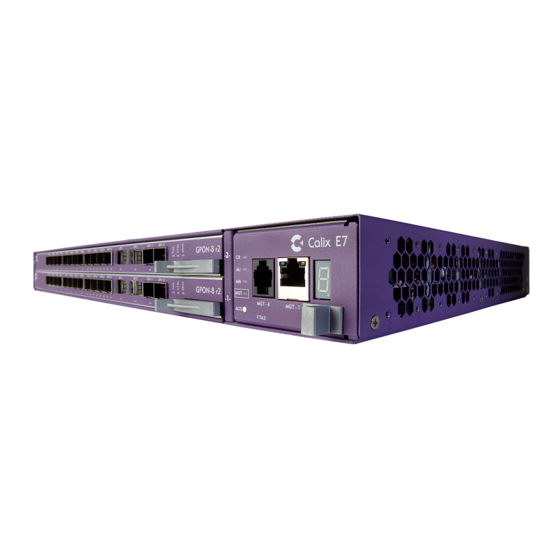
Ethernet, Metro Ethernet Forum (MEF) compliant business services, mobile backhaul, and protected GE aggregation. Calix E7-2 shelf views The Calix E7-2 system consists of the 2-slot E7-2 chassis, a removable fan module, and up to two high capacity line cards in universal card slots. Calix E7-2 (front) The Calix E7-2 line cards and fan module install into the front of the E7-2 shelf. - Page 9 The E7-2 power inputs (A/B), ground, alarm I/O, Craft management, and BITS timing interfaces are located on the rear of the E7-2 shelf. The E7-2 rear panel also has four RJ-21 copper interface connectors. Calix E7-2 cards The Calix E7-2 is equipped with two universal line card slots, supporting a flexible array of high capacity line cards, including: ...
-
Page 10: Product Dimensions
The Calix E7-2 fan module exterior dimensions follow: Height: 1.63 inches (4.1 cm) Width: 2.67 inches (6.8 cm) Depth: 10.82 inches (27.5 cm) Proprietary Information: Not for use or disclosure except by written agreement with Calix. © Calix. All Rights Reserved. -
Page 11: Chapter 2: Installation Considerations
This section covers the following topics: Installation guidelines Safety recommendations and notices Items required for installation (tools and materials) Preparations before you begin Proprietary Information: Not for use or disclosure except by written agreement with Calix. © Calix. All Rights Reserved. -
Page 12: Installation Guidelines
For safety, keep bystanders and other unauthorized personnel away from work operations at all times. If the E7-2 is to be installed in an outdoor cabinet, do not perform installation activities during thunderstorms or when the threat of lightning is present. -
Page 13: Safety Recommendations And Notices
ESD ALERT! Beware of electrostatic discharge. Follow standard ESD precautions. Always wear a grounded ESD wristband to avoid damaging the electronic equipment. Proprietary Information: Not for use or disclosure except by written agreement with Calix. © Calix. All Rights Reserved. -
Page 14: Required Items
Cool air intake and rear heat exhaust system to redirect airflow to the rear of the chassis RS-232 console cable (DB-9F to RJ-11M) to connect to a PC for console management Proprietary Information: Not for use or disclosure except by written agreement with Calix. © Calix. All Rights Reserved. - Page 15 Fiber splicer Fiber jumpers (LC for Ethernet interfaces; SC/UPC for GPON interfaces) Fiber management system (distribution, ducts, raceways, etc.) Proprietary Information: Not for use or disclosure except by written agreement with Calix. © Calix. All Rights Reserved.
-
Page 16: Preparations Before You Begin
As an environmentally hardened system, the Calix E7-2 is suitable for installation in network telecommunication facilities including outside plant (OSP) locations. The E7-2 requires one rack unit (1 RU) of mounting space on a standard 19- or 23-inch (48.26- or 58.42-cm) equipment rack. -
Page 17: Chapter 3: Installing The Calix E7-2
Chapter 3 Installing the Calix E7-2 This section describes how to install the Calix E7-2 chassis and components onto a standard equipment rack. Topics Covered This section covers the following topics: Installing the E7-2 chassis Grounding the E7-2 chassis ... -
Page 18: Installing The E7-2 Chassis
Calix offers the following rack mount options: E7-2 vertical mounting kits for vertical chassis orientation in 19- or 23-inch racks E7-2 ETSI rack mounting kit to provide a 75 mm forward offset limitation from the rack mounting rail To install the E7-2 chassis 1. - Page 19 To install an E7-2 vertical mounting frame 1. Identify the exact mounting location on the equipment rack for the E7-2 mounting frame. The frame requires approximately 22 inches (55.88 cm) of vertical rack space. 2. Install the mounting frame's top bracket as follows: a.
- Page 20 Attach the deflector to the rack using (4) supplied mounting screws (2 per side). After the vertical mounting frame is installed, you can install Calix E7-2 units onto the frame as required. Mount the E7-2 chassis with its right side (fan tray) on the bottom, to direct airflow upward.
-
Page 21: Grounding The Chassis
Note: The Calix-supplied ground cable uses UL-listed ground compression lugs (p/n 615-0001). If you use a ground cable other than the one supplied by Calix, be sure to coat the bare conductor with an appropriate antioxidant compound before making any crimp connections 2. - Page 22 Proprietary Information: Not for use or disclosure except by written agreement with Calix. © Calix. All Rights Reserved.
-
Page 23: Connecting Dc Power
Connecting DC Power The Calix E7-2 requires -48 VDC input power. The installation kit includes a 12-foot (3.66- meter) DC power cable with A and B leads. Note: The E7-2 must be installed in an Isolated DC return (DC-I) configuration, where the DC return is not connected to the grounding system. -
Page 24: Installing The Fan Module
2.2, FTA2 supports two fan speeds. Note: The E7-2 fan module includes an air filter for use in indoor/office environments only. Do not use the air filter for outdoor/cabinet deployments, to provide maximum airflow to the E7-2. - Page 25 3. Insert the fan module into the housing on the right side of the E7-2 chassis. 4. Push the fan module all the way back into the slot. The unit seats once the latch clicks into place. Proprietary Information: Not for use or disclosure except by written agreement with Calix.
-
Page 26: Installing E7-2 Line Cards
Installing E7-2 Line Cards The Calix E7-2 shelf is equipped with two universal line card slots. Install E7-2 line cards as described below. Note: The E7-2 shelf ships with a 'Blank' card (no circuitry) installed in Slot 2. For applications using only one E7-2 line card, the Blank card must occupy the second slot. - Page 27 Otherwise, install the Blank card into the vacant slot. Note: Due to airflow control considerations, the E7-2 shelf should not be operated with a vacant slot. If you are using only a single E7-2 line card at this time, install the Blank card into the other slot.
-
Page 28: Installing A Fiber Guide
On the left rack rail or top vertical mounting frame, remove the (2) mounting screws securing the E7-2 chassis to the rack or frame and hold the chassis in place. b. Align the bracket's rack mounting holes with the same holes used to mount the E7-2 chassis. - Page 29 1. Unpack the fiber guide kit, and locate the mid-mounting bracket. 2. On the left side of the E7-2 chassis (oriented horizontally or vertically), align one set of the bracket's captive screws with the forward mounting holes on chassis, and tighten the screws to secure the bracket to the chassis.
- Page 30 To install the fiber guide for an E7-2 mounted with an ETSI rack mount kit 1. Unpack the fiber guide assembly from its packaging. 2. Orient the fiber guide with the fiber management on the left outside. 3. Position the fiber guide's flat mounting plate against the right side of the installed ETSI mounting ear, aligning: ...
-
Page 31: Installing An Intake/Exhaust System
1. Unpack the intake/exhaust kit from its packaging. 2. Orient the left rear exhaust plenum on the left side of the E7-2 chassis with the vent in the back, aligning the plenum's inner mounting holes with the counterpart holes on the chassis. - Page 32 Position a mounting ear against the plenum, aligning its mounting holes with the counterpart holes on the plenum. b. Attach the mounting ear to the plenum using (4) supplied flathead screws. Proprietary Information: Not for use or disclosure except by written agreement with Calix. © Calix. All Rights Reserved.
-
Page 33: Chapter 4: Wiring The E7-2 Network Interfaces
Chapter 4 Wiring the E7-2 Network Interfaces This section describes how to wire out the Calix E7-2 network interfaces, including management, alarms, and service line interfaces. Topics Covered This section covers the following topics: Connecting the E7-2 management interfaces ... -
Page 34: Connecting The E7-2 Management Interfaces
(labeled MGT-1). The rear Ethernet management port is located on the E7-2 rear panel (labeled MGMT-3). Use the front Ethernet port for (temporary) local Craft access to the E7-2. If you require a permanent out-of-band management connection to the E7-2, Calix recommends using the rear Ethernet management port to connect to the LAN. - Page 35 3. Connect the cable's other end to a LAN Ethernet hub or switch. For instructions to log in to the E7-2 management interface, refer to the Calix E7 User Guide. Proprietary Information: Not for use or disclosure except by written agreement with Calix.
-
Page 36: Connecting To The Rs-232 Serial Port
Connecting to the RS-232 Serial Port The E7-2 has an RS-232 serial port that you can connect to a PC for console management connections. The serial port is located on the E7-2 fan module (RJ-11F connector). Note: Calix provides an optional RS-232 console cable, or you may supply your own cable with an RJ-11 male connector on one end and a DB-9 female connector on the other end. -
Page 37: Wiring The External Alarm And Timing Interfaces
E7-2 rear panel. Wiring External Alarms The E7-2 supports eight external alarm input/output (I/O) positions via wire wrap pins located on the E7-2 rear panel. The eight external alarm positions include seven inputs and one output position. Output... - Page 38 1. Get up to eight 24 AWG wire pairs of sufficient length to reach the far-end contacts from the E7-2. 2. At the E7-2 end, strip approximately one inch (2.54 cm) of insulation from the alarm wire ends. 3. Wire the E7-2 alarm inputs as follows: a.
-
Page 39: Wiring The Bits Timing Interface
RNG- OUT (A) OUT (B) You can link up to ten collocated E7-2 shelves to share a BITS timing input. Calix offers a connectorized daisy-chain BITS cable, or you can wire-wrap the individual daisy-chain links between shelves. To wire the BITS timing input interface 1. - Page 40 To wire the BITS timing output interface 1. Get up to two 24 AWG shielded 2-wire cables of sufficient length to reach the next E7-2 shelf. Use one cable to provide a single link (A only), or two cables for a redundant link (A + B).
-
Page 41: Connecting The E7-2 Line Interfaces
You must install pluggable modules into the cards to equip the ports. Calix offers a full suite of optical and copper pluggable modules to support a wide array of applications. The E7-2 10GE and GPON ports require only Calix-supplied modules, but E7- 2 GE ports can use SFP modules from Calix or other suppliers, with some restrictions. -
Page 42: Installing Pluggable Transceiver Modules
Installing Pluggable Transceiver Modules Install pluggable transceiver modules into the E7-2 line cards to equip the ports for optical or copper interface connections. To install pluggable transceiver modules 1. Unpack the pluggable module. Remove the dust cover from the transceiver interface, if present. -
Page 43: Connecting Fibers
1. Route fibers (or copper Ethernet cables) to the E7-2 shelf, approaching from left side. Important: Route fibers to the left side of the E7-2 shelf to ensure visibility of system and card status LEDs located on the right side of the E7-2 shelf. -
Page 44: Connecting To The Copper Access Interfaces
(provided by Calix in the E7-2 field install kit). The head of the cable tie must align with the bottom edge of the connector to achieve a robust connection. - Page 45 1. Route the 25-pair equipment interface cables (RJ-21 connectors) to the rear of the E7-2 shelf. 2. On the rear of the E7-2, terminate the interface cable(s) for slot 1 to the RJ-21 connector labeled P1 or P2 and the interface cable(s) for slot 2 to the RJ-21 connector labeled P3 or P4, as required for the installed line card(s).
- Page 46 3. Dress the cable and secure them to the equipment rack (and cable tie bars) every 6–8 inches (15.24–20.32 cm) with cable ties or lacing cord. Proprietary Information: Not for use or disclosure except by written agreement with Calix. © Calix. All Rights Reserved.
-
Page 47: Chapter 5: Maintenance
Chapter 5 Maintenance This chapter describes how to perform routine maintenance on worn or failed E7-2 equipment. Topics Covered This chapter covers the following topics: Replacing pluggable transceiver modules on E7-2 line cards Replacing an E7-2 line card ... -
Page 48: Replacing Pluggable Transceiver Modules
To replace a pluggable transceiver module 1. Disconnect the fiber(s) from the module to replace, if present. 2. Remove the pluggable module from the E7-2 line card as follows: a. Unlock the latch on the module, if so equipped (latch styles vary). -
Page 49: Replacing An E7-2 Line Card
Carefully slide the card out of the slot, and place it in protective packaging. Return the faulty unit to Calix. 4. Insert a replacement line card into the vacant slot. See Installing E7-2 Line Cards (on page 26) for detailed instructions. -
Page 50: Replacing The Fan Module
FTA supports two fan speeds. FTA2 supports four fan speeds with E7 release 2.2 or higher; in releases prior to 2.2, FTA2 supports two fan speeds. Note: Do not leave a powered E7-2 operating for more than a few minutes without a fan module installed, to avoid overheating the system. -
Page 51: Fan Filter Maintenance
Calix recommends conducting a visual inspection of the filter every three months. When the filter becomes visibly clogged with dust or dirt, the filter must be cleaned. Note: Do not leave a powered E7-2 operating for more than a few minutes without a fan module installed, to avoid overheating the system. - Page 52 Note: If the filter is badly worn, replace it with a new filter (available from Calix). 4. Reinstall the filter into the fan module, and then install the fan module into the E7-2 chassis. Proprietary Information: Not for use or disclosure except by written agreement with Calix.
-
Page 53: Chapter 6: Reference Information
Appendix A Reference Information This appendix provides general reference information about the Calix E7-2 Ethernet service access platform. Topics Covered This appendix covers the following topics: E7-2 specifications E7-2 LED behavior RS-232 serial port pin assignments Fiber handling techniques Proprietary Information: Not for use or disclosure except by written agreement with Calix. -
Page 54: E7-2 Specifications
FCC Part 15 Class A Network Equipment-Building System (NEBS) Level 3: Telcordia GR-63-CORE Telcordia GR-1089-CORE Telcordia GR-3028-CORE ETSI EN 300 019, ETSI 300 386 Proprietary Information: Not for use or disclosure except by written agreement with Calix. © Calix. All Rights Reserved. -
Page 55: E7-2 Led Behavior
E7-2 LED Behavior System status indicators The Calix E7-2 fan module has four LEDs to indicate system alarm and operational status. Name Color Status Description Critical A critical alarm is present in the system No critical alarms are present in the system... - Page 56 Port status indicators Each interface port on an E7-2 line card has an LED located below its module socket to indicate port status. (E7-2 cards contain a mix of some or all port types listed below). Port Color Status Description...
-
Page 57: Rs-232 Serial Port Pins
Pin 4 Pin 5 RJ-11F Connector Calix offers an RS-232 console cable (DB-9F to RJ-11M) to connect a PC to the E7-2 serial port. Alternatively, you may use the pin assignments below to make your own console cable, as required. -
Page 58: Pin Assignments
RJ-21 Pin Assignments This topic provides the RJ-21 connector pin assignments. To wire the Calix E7-2 for DSx services (e.g., VDSL2/POTS), use 25-pair cables with an RJ-21 male connector. Calix recommends that the RJ-21 connector on the 25-pair cables use a 110 degree exit or 90 degree exit (at pins 1 and 26). - Page 59 YL/BR SL/YL Ring YL/SL BL/VI Ring VI/BL OR/VI Ring VI/OR GN/VI Ring VI/GN BR/VI Ring VI/BR SL/VI Not used VI/SL Not used Proprietary Information: Not for use or disclosure except by written agreement with Calix. © Calix. All Rights Reserved.
-
Page 60: Fiber Handling Techniques
Important: Calix strongly recommends using the fusion splice method for all fiber splices. Jacket preparation (OSP fiber) Remove the jacket, buffer tubes and strength member using a wire stripper or cutting pliers. - Page 61 Never attempt to insert the connector by gripping the white or green flexible shroud. This may cause the fiber to kink in the jacket, introducing unwanted noise to the line. Proprietary Information: Not for use or disclosure except by written agreement with Calix. © Calix. All Rights Reserved.
- Page 62 Proprietary Information: Not for use or disclosure except by written agreement with Calix. © Calix. All Rights Reserved.
Need help?
Do you have a question about the E7-2 and is the answer not in the manual?
Questions and answers