Eaton M-Max series Quick Start Manual
Adjustable frequency drive
Hide thumbs
Also See for M-Max series:
- Quick start manual (40 pages) ,
- User manual (204 pages) ,
- Operating instructions manual (199 pages)
Table of Contents
Advertisement
Quick Links
Download this manual
See also:
User Manual
Advertisement
Table of Contents

Related Manuals for Eaton M-Max series


Summary of Contents for Eaton M-Max series
- Page 1 M-Max Series Effective February 2010 adjustable frequency drive Supersedes June 2009 Quick start guide...
- Page 3 February 2010 Important notice—please read The product discussed in this literature is subject to terms and conditions outlined in Eaton selling policies. The sole source governing the rights and remedies of any purchaser of this equipment is the relevant Eaton selling policy.
-
Page 4: Table Of Contents
M-Max Series adjustable frequency drive February 2010 Table of contents List of Figures ............ -
Page 5: List Of Tables
List of figures Figure 1: M-Max Series Adjustable Frequency Drive ....... -
Page 6: Safety
M-Max Series adjustable frequency drive February 2010 Safety Definitions and symbols VOLTAGE This symbol indicates high voltage. It calls your attention to items or operations that could be dangerous to you and other persons operating this equipment. Read the message and follow the instructions carefully. -
Page 7: Cautions
February 2010 Cautions and notices Read this manual thoroughly and make sure you understand the procedures before you attempt to install, set up, or operate Eaton’s M-Max Series adjustable frequency drive. Cautions CAUTION Be ABSOLUTELY sure not to connect two functions to one and same output in order to avoid function overruns and to ensure flawless operation. - Page 8 M-Max Series adjustable frequency drive February 2010 Suitable safety hardware and software measures should be implemented for the I/O interface so that an open circuit on the signal side does not result in undefined states in the automation devices. Ensure a reliable electrical isolation of the extra-low voltage of the 24V supply.
- Page 9 M-Max Series adjustable frequency drive February 2010 MN04020002E For more information visit: www.eaton.com...
- Page 10 M-Max Series adjustable frequency drive February 2010 viii MN04020002E For more information visit: www.eaton.com...
-
Page 11: M-Max Series
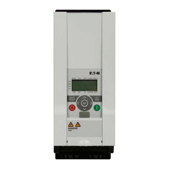
Notes about the M-Max Series product enhancement This third edition of the quick reference guide describes the extended functionality (as of production date January 2010, see Figure 1 ) of the M-Max Series of adjustable frequency drives. Key features of this enhancement are:... -
Page 12: Figure 2: Control Signal Terminals
This quick reference guide is a summary of manual MN04020001E and contains technical data, parameter lists and information about operating the adjustable frequency drives. It is intended to support experienced, qualified users in the use of the M-Max Series adjustable frequency drive. -
Page 13: Writing Conversions
MN04020001E parameter configuration, please consult manual The complete documentation for the M-Max Series of frequency converters is stored electronically on a CD-ROM. This CD-ROM is part of the scope of supply. Additional information on the series described here can be found on the Internet under: www.eaton.com/M-Max... -
Page 14: Rated Operational Data On The Nameplate
M-Max Series adjustable frequency drive February 2010 Rated operational data on the nameplate The device-specific rated operational data for M-Max Series adjustable frequency drives is shown on the nameplate on the device's side and on the back of the control signal terminal cover. -
Page 15: Table 2: General Rated Operational Data
M-Max Series adjustable frequency drive February 2010 General Rated Operational Data Table 2: Technical data Unit Value General Standards and regulations EMC: IEC/EN 61800-3, Safety: IEC/EN 61800-5, UL 508C Certifications and manufacturer’s EMC: CE, CB, c-Tick declarations on conformity Safety: CE, CB, UL, cUL, phenum rated... - Page 16 M-Max Series adjustable frequency drive February 2010 Table 2: General Rated Operational Data (continued) Technical data Unit Value Power Section (continued) Mains network configuration Center-point grounded star network (TN-S network) (AC power supply network) Phase grounded AC networks are not permitted.
-
Page 17: Technical Data
M-Max Series adjustable frequency drive February 2010 Technical Data Table 3: Technical Data Rated Opera- Overload tional Current Current (150%) Assigned Motor Rating P (230V, 50 Hz) P (230V, 60 Hz) e150 Installation Part Number [kW] [hp] Size Power Connection Voltage: 1 AC 115V, 50/60 Hz (94 – 132V ± 0%, 45 – 66 Hz ± 0%) MMX11AA1D7.. -
Page 18: Control Signal Terminals
M-Max Series adjustable frequency drive February 2010 Table 3: Technical Data (continued) Rated Opera- Overload tional Current Current (150%) Assigned Motor Rating P (230V, 50 Hz) P (230V, 60 Hz) e150 Installation Part Number [kW] [hp] Size Power Connection Voltage: 3 AC 400V/460V, 50/60 Hz (323 – 528V ± 0%, 45 – 66 Hz ± 0%) MMX34AA1D3.. -
Page 19: Table 4: Cable Cross Section (Cu): 0.5 - 1.5 Mm
M-Max Series adjustable frequency drive February 2010 Table 4: Cable Cross Section (Cu): 0.5 – 1.5 mm Terminal Blocks Signal Factory Setting Description +10V Output nominal voltage — Maximum load 10 mA, reference potential GND Analog signal input 1 Frequency reference value 0 –... -
Page 20: Block Diagram
M-Max Series adjustable frequency drive February 2010 Block diagram The following diagrams show all the terminals on an M-Max Series adjustable frequency drive and their functions at the default settings. 1 AC 120V L2/N 120 Ω –C 200 kΩ 200 kΩ... - Page 21 M-Max Series adjustable frequency drive February 2010 1 AC 240V 1 AC 230V L2/N 120 Ω –C 200 kΩ 200 kΩ 200 Ω 200 Ω 3 AC 230V Figure 5: MMX12 Block Diagram MN04020002E For more information visit: www.eaton.com...
- Page 22 M-Max Series adjustable frequency drive February 2010 3 AC L2/N 15 16 200 Ω –C 200 kΩ 200 kΩ 200 Ω 200 Ω 3 AC Figure 6: Block Diagram MMX32 and MMX34 Connection terminals R+ and R– for external braking resistance (optional), only with MMX34…4D3…, MMX34…5D6…, MMX34…7D6…, MMX34…9D0, MMX34…012…...
-
Page 23: Operation
M-Max Series adjustable frequency drive February 2010 Operation Checklist for commissioning Before placing the adjustable frequency drive into operation, make sure to check the following (checklist): Activity Note Installation and wiring have been carried out in accordance with the corresponding installation instructions IL04020001E). -
Page 24: Hazard Warnings
M-Max Series adjustable frequency drive February 2010 Hazard warnings Please observe the following notes. DANGER Commissioning is only to be completed by qualified technicians. DANGER Hazardous voltage! The safety instructions on pages iv and v must be followed. DANGER The components in the adjustable frequency drive’s power section are energized if the supply voltage (line voltage) is connected. - Page 25 M-Max Series adjustable frequency drive February 2010 CAUTION Any contactors and switching devices on the power side are not to be opened during motor operation. Inching operation using the power switch is not permitted. Contactors and switching devices (repair and maintenance...
-
Page 26: Error And Warning Messages
M-Max Series adjustable frequency drive February 2010 Error and Warning Messages Introduction The M-Max Series adjustable frequency drive have several internal monitoring functions. When deviations from the optimal operating status are detected, faults (FAULT) and warning messages (ALARM) are differentiated between. Error messages Faults can cause faulty functionality and technical defects. -
Page 27: Fault Log (Flt)
M-Max Series adjustable frequency drive February 2010 Fault log (FLT) The last nine faults can be called up and shown in succession in the fault log (FLT). To do this, select menu level FLT ( ). With arrow keys you can separately call up faults F1 to F9. -
Page 28: Table 5: List Of Fault Messages (F) And Warning Messages (Al)
M-Max Series adjustable frequency drive February 2010 Table 5: List of Fault Messages (F) and Warning Messages (AL) Display Designation Possible Cause Instructions Overcurrent • The adjustable frequency drive has • Check the load detected an excessive current (> 4 x I •... - Page 29 M-Max Series adjustable frequency drive February 2010 Table 5: List of Fault Messages (F) and Warning Messages (AL) (continued) Display Designation Possible Cause Instructions Internal Environment interferences or If the fault occurs again, please communication faulty hardware contact your Eaton representative error or call 877-ETN-CARE (386-2273).
-
Page 30: Parameters
M-Max Series adjustable frequency drive February 2010 Parameters Control unit The following figure shows and indicates the elements of the M-Max’s Series integrated control unit. Figure 9: View: Control Unit With LCD Display, Function Keys, and Interface Table 6: Control Unit Elements... - Page 31 M-Max Series adjustable frequency drive February 2010 Actuating the arrow keys causes the active value to increase or decrease the parameter number or the function by one unit. If you hold one of the two arrow keys pressed, the respective units increase or decrease automatically.
-
Page 32: Display Unit
M-Max Series adjustable frequency drive February 2010 Display unit The following shows the display unit (LCD display with all display elements) READY STOP ALARM FAULT KEYPAD Figure 10: LCD Display (Areas) The display unit consists of a backlit liquid crystal display (LCD). It is divided into four areas:... -
Page 33: General Information On Menu Navigation
M-Max Series adjustable frequency drive February 2010 General information on menu navigation By applying the specified supply voltage to the connection terminal L2/N and L3 (MMX11), L1 and L2/N (MMX12) or L1, L2/N and L3 (MMX32, MMX34), the adjustable frequency drive automatically runs the following functions: The lighting of the LCD display is switched on and all segments are actuated briefly. -
Page 34: Setting Parameters
M-Max Series adjustable frequency drive February 2010 Setting parameters The following table shows an example of how you can select and set parameters. Table 8: LCD Display in Operation Sequence Commands Display Description Measured value 1.1 READY STOP ALARM FAULT The display changes automatically with the value of the output frequency 0.00 Hz... - Page 35 M-Max Series adjustable frequency drive February 2010 Table 8: LCD Display in Operation (continued) Sequence Commands Display Description If the parameter value is flashing, you can use READY STOP ALARM FAULT the two arrow keys to change the value within the permitted range.
-
Page 36: Parameter Menu (Par)
M-Max Series adjustable frequency drive February 2010 Parameter menu (PAR) You have access to all M-Max Series parameters in the parameter menu (PAR) (see “List of parameters” on Page 30). READY STOP ALARM FAULT READY STOP ALARM FAULT Display in... - Page 37 M-Max Series adjustable frequency drive February 2010 P1.1 = 1 P1.1 = 0 P1.2 = 0 P1.1 = 0 P1.2 = 1 P1.2 = 1 P1.2 = 2 P1.2 = 2 P1.1 = 3 P1.1 = 3 P6.1 P1.3 P11.7 P12.3...
-
Page 38: Quick Start Wizard
M-Max Series adjustable frequency drive February 2010 Quick start wizard The quick-start wizard guides you in the quick configuration through all important settings that have to be made or that you should check for your application (see A in Figure 13). The parameters that are called during the process are listed in Table 10 on Page 32 in column Basic (Standard Drive). -
Page 39: Example: Motor Parameters (P7)
M-Max Series adjustable frequency drive February 2010 Example: Motor parameters (P7) For optimal operation, you should enter the ratings plate information for the motor here. This information makes up the base values for the motor controller (electrical reproduction). P7. 1 P7. -
Page 40: List Of Parameters
M-Max Series adjustable frequency drive February 2010 List of parameters Detailed information on the individual parameters is provided in the manual MN04020001E Quick configuration (basis) When first switching on or after activating the default settings (S4.2 = 1), you are guided step by step through the provided parameters by the quick-start assistant. - Page 41 M-Max Series adjustable frequency drive February 2010 Table 9: Quick Configuration (continued) Access Right Factory User Designation Value Range Setting Setting P6.6 — Deceleration 0.1 – 3000s time (dec1) P6.7 — Start function 0 = Acceleration time (ramp) 1 = Flying restart circuit P6.8...
-
Page 42: Table 10: Predefined Application Parameters From Parameter P1.2
M-Max Series adjustable frequency drive February 2010 Table 10: Predefined Application Parameters From Parameter P1.2 Basic Feed Unit Parameters Designation (Standard Drive) Pump Drive Fan Drive (High Load) P1.1 Parameter 1 = Only quick 1 = Only quick 1 = Only quick... -
Page 43: All Parameters
M-Max Series adjustable frequency drive February 2010 All Parameters When first switching on or after activating the default settings (S4.2 = 1) parameter P1.1 must be set to 0 for access to all parameters. Table 11: All Parameters Access Right... - Page 44 M-Max Series adjustable frequency drive February 2010 Table 11: All Parameters (continued) Access Right Factory User Designation Value Range Setting Setting Digital Input (continued) P3.3 Start signal [2] like P3.2 P3.4 Reversing like P3.2 P3.5 External fault like P3.2 (N/O) P3.6...
- Page 45 M-Max Series adjustable frequency drive February 2010 Table 11: All Parameters (continued) Access Right Factory User Designation Value Range Setting Setting Digital Input (continued) P3.26 1413 First/second like P3.2 source for I/O reference value P3.27 1414 Second like P3.2 parameter set P3.28...
- Page 46 M-Max Series adjustable frequency drive February 2010 Table 11: All Parameters (continued) Access Right Factory User Designation Value Range Setting Setting Digital Output (continued) P5.1 RO1 signal 16 = Flow control active 17 = Flow control, single step (con’t.) 18 = Flow control, program cycle...
- Page 47 M-Max Series adjustable frequency drive February 2010 Table 11: All Parameters (continued) Access Right Factory User Designation Value Range Setting Setting Drives Control P6.1 Remote control 1 = Control signal terminals (I/O) place 2 = Control unit (KEYPAD) 3 = Field bus (BUS) P6.2...
- Page 48 M-Max Series adjustable frequency drive February 2010 Table 11: All Parameters (continued) Access Right Factory User Designation Value Range Setting Setting Drives Control (continued) P6.19 — Acceleration 0.1 – 3000s 10.0 time (acc2) P6.20 — Deceleration 0.1 – 3000s 10.0 time (dec2) P6.21...
- Page 49 M-Max Series adjustable frequency drive February 2010 Table 11: All Parameters (continued) Access Right Factory User Designation Value Range Setting Setting Protective Functions P8.1 — 4 mA reference 0 = Deactivated value error 1 = Warning 2 = Error, stop according to P6.8 P8.3...
- Page 50 M-Max Series adjustable frequency drive February 2010 Table 11: All Parameters (continued) Access Right Factory User Designation Value Range Setting Setting PID Controller (continued) P9.6 — PID controller, 0 = Field bus (option) actual value 1 = AI1 2 = AI2 P9.7...
- Page 51 M-Max Series adjustable frequency drive February 2010 Table 11: All Parameters (continued) Access Right Factory User Designation Value Range Setting Setting Fixed Frequencies (continued) P10.4 Fixed frequency 0.00 – P6.4 Hz 20.00 P10.5 Fixed frequency 0.00 – P6.4 Hz 25.00 P10.6...
- Page 52 M-Max Series adjustable frequency drive February 2010 Table 11: All Parameters (continued) Access Right Factory User Designation Value Range Setting Setting V/Hz Characteristic Curve (continued) P11.8 — Motor control 0 = Frequency control (V/Hz) mode 1 = Speed control (vector) P11.9...
- Page 53 M-Max Series adjustable frequency drive February 2010 Table 11: All Parameters (continued) Access Right Factory User Designation Value Range Setting Setting Logic Function P13.1 1453 — Logic function – 0 = Deactivated select input A 1 = Ready to start (READY)
- Page 54 M-Max Series adjustable frequency drive February 2010 Table 11: All Parameters (continued) Access Right Factory User Designation Value Range Setting Setting Second Parameter Set (continued) P14.6 1349 — Motor[2], rated 30 – 320 Hz frequency Motor rating plate) P14.7 1343 —...
- Page 55 M-Max Series adjustable frequency drive February 2010 Table 11: All Parameters (continued) Access Right Factory User Designation Value Range Setting Setting Communications S2.1 — Communication Format xx.yyy status xx = number of error messages (0 – 64) yyy = number of correct messages (0 –...
- Page 56 M-Max Series adjustable frequency drive February 2010 Table 11: All Parameters (continued) Access Right Factory User Designation Value Range Setting Setting User Set S4.1 — Display contrast 0 – 15 S4.2 — Factory setting 0 = Retain current values (WE)
- Page 58 Eaton’s Electrical Sector is PowerChain Management a global leader in power solutions help enterprises distribution, power quality, achieve sustainable and control and automation, and competitive advantages through monitoring products. When proactive management of the combined with Eaton’s full-scale power system as a strategic,...
Need help?
Do you have a question about the M-Max series and is the answer not in the manual?
Questions and answers