
Related Manuals for Steca coolcept StecaGrid 1500


Summary of Contents for Steca coolcept StecaGrid 1500
- Page 1 coolcept coolcept-x Installation and operating instructions 747.431 | Z09.2 | 2016-02-18...
-
Page 2: Table Of Contents
Table of contents Preface................. 4 General information............5 General safety instructions........... 5 Identification..............6 Scope of delivery............8 Intended use..............8 About this manual............9 Structure and function............. 12 Housing..............12 Operating buttons............. 14 Display............... 14 Cooling..............21 Grid monitoring............22 Data communication.......... - Page 3 Liability, commercial guarantee, legal guarantee..83 Contact................84 Appendix................85 Assembly..............86 Bore dimension drawing for coolcept devices... 86 Bore dimension drawing for coolcept-x devices..87 AC plug..............88 Phoenix Contact SUNCLIX (DC connector)....91 747,431 | Z09.2 | 18/02/2016...
-
Page 4: Preface
Preface Thank you for choosing inverters from the coolceptproduct line of Steca Elektronik GmbH . By using solar energy, you are making a significant contribution to environmental protection; by reducing the amount of carbon dioxide (CO ) and other harmful gases that burden the earth's atmosphere. -
Page 5: General Information
General information General safety instructions This document is part of the product. Install and use the device only after reading and understanding this document. Always perform the measures described in this document in the sequence specified. Keep this document in a safe place for the entire service life of the device. -
Page 6: Identification
Safety information on the device (coolcept Indoor) ① Dangerous voltages can remain present on the components up to 10minutes after switching off the DC circuit breaker and the line circuit breaker. ② Read and follow the manual! ③ Serial number as a bar code and in plain text Safety information on the device (coolcept Indoor) - Page 7 Feature Description See Appendix ⇒ Certificates and Certificates www.stecasolar.com ⇒ coolcept – coolcept-x Optional accessories External data loggers: – WEB‘log from Meteocontrol – Solar-Log from Solare Datensysteme Termination plug for RS485 bus – IP21: 752,856 – IP65: 740,864 Rating plate ①...
-
Page 8: Scope Of Delivery
Scope of delivery Inverter ①, type coolcept (plastic housing) or coolcept-x (stainless steel housing, IP65) Mounting plate ② for type coolcept or coolcept-x AC plug ③ 1 pair SUNCLIX plug-in connectors ④ 3 sealing caps (for RJ45 socket; only coolcept-x) ⑤ Brief installation and operating instructions ⑥... -
Page 9: About This Manual
Potential curves of the = Potential between the plus (+) and minus (–) DC‑connections plus (+) and minus (–) DC StecaGrid 1500/2000 and 1500x/2000x connections with respect to PE 375 V 375 V = 75 V DC (+) = 350 V DC (+) −75 V DC (−) -
Page 10: Target Group
This manual contains all information that a specialist needs to set up and operate the inverters. Follow the instructions of the respective manufacturers when installing other components (e.g. PV generator, cables). 2.5.2 Target group Unless otherwise indicated, the target audiences of this manual are technical professionals and system operators. - Page 11 Signal words Keywords used in conjunction with the symbols described: Signal word Meaning DANGER! This combination of symbol and signal word indicates an immediate dangerous situation that will result in death or serious injury if it is not avoided. WARNING! This combination of symbol and signal word indicates a possible dangerous situation that can...
-
Page 12: Structure And Function
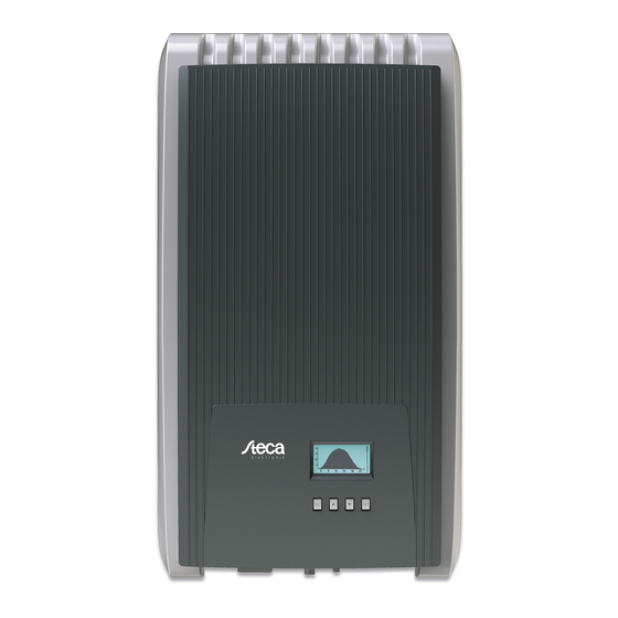
Structure and function Housing 3.1.1 coolcept ① Hood ② Display (monochrome, 128 x 64 pixels) ③ Rating plate, serial number, warnings ④ Operating buttons: ESC, r, s, SET (from left to right) ⑤ 1x AC connection ⑥ 1x DC connection Minus (−) for PV generator (Phoenix Contact SUNCLIX, touch protection) ⑦... - Page 13 3.1.2 coolcept-x ① Hood ② Display (monochrome, 128 x 64 pixels) ③ Rating plate, serial number, warnings ④ Operating buttons: ESC, r, s, SET (from left to right) ⑤ 1x AC connection ⑥ Pressure equalization membrane ⑦ 1x RJ45 socket (RS485 bus) ⑧...
-
Page 14: Operating Buttons
Operating buttons The operating buttons ④ in Ä Chapter 3.1.1 ‘coolcept’ on page 12 and in Ä Chapter 3.1.2 ‘coolcept-x’ on page 13 have the following functions: Function Button Action General guided operation Press briefly Goes to the next higher menu Navigates 1 step back level Discards any changes... - Page 15 Notice The display reacts slower at very low temperatures. In particular, this can apply for coolcept-xdevices if they are used outdoors. 3.3.2 Information The information shown on the display is described below using illustrative examples. Status display The status display shows the following values: ①...
- Page 16 Graphical yield (day, Daily, monthly and annual yields can be displayed graphically in a month, year) chart. ① Period on an individual yield (here: day yield) ② Y axis 1) 2) 3) ③ X axis: Time in hours/days/months/years ④ Total of all individual yields shown in the diagram, in kWh The graphical representation can show annual yields for the last 20 years.
- Page 17 Network: Network parameters, partially configurable under Settings ▶ Network – Host name: Unique name in the network – DHCP status: DHCP on/off – Link status: Status of the network connection – IP address: IP address of the inverter – Subnet mask: Subnet mask of the inverter –...
- Page 18 Max. daily yield: The maximum daily yield achieved Operating hours: The operating hours during which the device has been connected to the grid (including night-time hours). Total yield: Yield since commissioning savings: CO savings achieved since commissioning Measurement is always displayed (cannot be switched off) Possible causes: –...
-
Page 19: Service Menu
DNS address: IP address of the DNS server web-portal: Settings at the web portal – Web portal setting: Disabling of data transmission and selection of a web portal – Re-transmission: Data in the inverter is transmitted a second time – Connection check: Checks the internet connection and indicates the result 3.3.4... - Page 20 Delete country setting After the country setting has been deleted the device restarts anew and displays the guided 1st commissioning menu. Factory setting Resetting the device to the factory setting deletes the following data: Yield data Event messages Date and time Country setting Display language Network settings...
-
Page 21: Cooling
The reactive power characteristic curve must be set during 1st commissioning if this is prescribed for the previously selected country. The following applies: 3 characteristic curves are available for selection (Fig. left): – Default. char. curve (pre-defined) – Enter char. curve (manually adjustable) –... -
Page 22: Grid Monitoring
The inverter is convection cooled via fins on the front and rear side. A maintenance-free fan circulates the heat within the closed housing evenly over the entire surface of the housing. Grid monitoring The inverter constantly monitors the mains grid parameters while feeding the grid. - Page 23 This service is free of charge for a period of 2 years from the time of registration. The following applies: Before the Internet portal can be used, the user must go to www.steca.com/portal to register. See more Ä Chapter 5.4 ‘Internet portal’ on page 53 The local network settings must be set at the inverter in order to establish a connection to the Internet portal server.
- Page 24 Furthermore, you can use the TCP/IP interface to display yield data and other information as HTML pages. You need a PC connection to indicate the data. The HTML pages can be displays by means of a browser, such as Mozilla Firefox. To enable the connection, enter the IP address of the inverter (see inverter status indication) in the browser.
- Page 25 The inverter has two RS485 interfaces (RJ45 sockets) on the lower side of the casing. The beginning and end of the RS485 bus must be terminated; Ä Chapter 3.6.5 ‘RS485 termination’ on page 28. Standard RJ45 cables can be used as bus cables (Cat-5 patch cables, not supplied).
- Page 26 Notice If in the country setting Italy is set, then the RS485 bus must be connected as follows to enable control through an external device in accordance with CEI 0-21. – External fast switch-off (ital.: Teledistacco): If the lines 3 and 8 of the RS485 bus connected, e.
- Page 27 This is available on our homepage see http:// www.steca.com/index.php?StecaGrid_User_de – Connection to the inverter via optional adapter RS485⇔USB is possible; the adapter is available from Steca under Article Number 746.610 (IP21) or 737.707 (IP65). – Load firmware updates (for technical professionals only)
- Page 28 3.6.4 Alternative RS485 data connection cable NOTICE! Material damage caused by electrical voltage! The alternative data connection cable may only be manufactured by professional personnel. The alternative data connection cable is a Cat-5 cable for long data connections. The following applies to the alternative data connection cable: The total length of the RS485 bus must not exceed 1,000 m (Master/first inverter to last inverter).
- Page 29 The external data logger (at the start of the data connection) must be terminated according to the manufacturer's specifications. The last inverter (at the end of the data connection) is terminated by plugging the optionally available termination plug into the free RJ45 socket (for RS485 bus) (see table in Ä...
- Page 30 Fig. 10: Contact assignment (= line number) of the RJ10 plug Device Inverter Signal Connection RJ10 Contact Data A Data B Ground — NOTICE! Danger of destroying the Modbus RTU input of the inverter. Contact 4 of the RJ10 socket of the inverter carries voltage <20V.
-
Page 31: Installation
Installation Safety measures during installation Observe the following safety notes when performing the work described in Section Installation . DANGER! Risk of death by electrocution! – Only technical professionals may perform the work described in Section Installation . – Do not connect cables to the inverter until explicitly asked to do so in the manual. - Page 32 Check that all pins of the AC plug are free of voltage. Use a suitable voltmeter for this (do not use a simple neon phase checker). NOTICE! Risk of damage to the inverter or derating! – The mounting location must satisfy the following conditions: –...
-
Page 33: Mounting The Inverter
Mounting the inverter Fastening the mounting plate u Screw the mounting plate to the mounting surface using 4 screws: Use screws (and dowels etc.) appropriate for the weight of the inverter. The mounting plate must lie flat on the mounting surface and the metal strips at the sides must point forwards (Fig. - Page 34 ① ② Fig. 11: Position of the sticker for covering the Protection Class II symbol Completely cover the Protection class II symbol using the small sticker provided, as shown in Fig. 11. Attaching the inverter on the mounting plate NOTICE! How to remove the inverter from the mounting plate is described under Ä...
-
Page 35: Prepare Ac Connection
Prepare AC connection 4.3.1 Miniature circuit breaker Information on the required line circuit breaker and the cables to be used between the inverter and the line circuit breaker is provided in Ä Chapter 9.2 ‘AC cables and line circuit breakers’ on page 81. 4.3.2 Fault current circuit breaker If the local installation regulations require the installation of an... - Page 36 Notice With a mains grid voltage of 100 V ... 127 V, the inverter can be connected between the L1, L2 and L3 external conductors as follows: 2-phase mains grids – N and L are connected between the L1 – L2 ②...
-
Page 37: Prepare Dc Connections
Fig. 12: Connection of N and PE in the AC plug (above) or junction box (below) ① Connection cable between N and PE with the connection point inside the AC plug ② External conductor L1 ③ External conductor L2 ④ Connection cable between N and PE with the connection point inside the junction box ⑤... -
Page 38: Preparing The Data Connection Cable
NOTICE! Risk of damage to the inverter and the modules. Connect the opposing connectors for the DC connections to the DC cable, observing the correct polarity. Attach the connector plug counterparts to the DC cable according to the manufacturer's instructions; see Appendix. Preparing the data connection cable If a data connection is required, use a standard RJ45 cable (patch cable, Cat5) or construct an alternative data... -
Page 39: Initial Commissioning Of The Inverter
Countries table on the Steca homepage, www.steca.com/Wechselrichter-Wohnsiedlung. The country can only be set once! Contact the Steca Technical Support if you have set the wrong country. If the Countries table does not list your country, select a country with stricter specifications. - Page 40 NOTICE! – When a check list item is called up, the corresponding check box is automatically selected. – Initial commissioning is completed by calling up the Finish item. – Finish can only be performed when all other check boxes are selected. Press rs to select a check list item.
- Page 41 Press s. The month is selected. ð Repeat steps 1 to 3 for the month. Press s. The year is selected. ð Repeat steps 1 to 3 for the year. Press ESC. ✓ The check list is shown. Time format Press rs to select a time format.
- Page 42 Country selection NOTICE! The country can only be set once! Press rs to select a country. Press SET. Press ESC. the dialog shown at the left is displayed. ð Press ESC to select a different country by performing step 1 and step 2, or Press SET for a longer period of time (>...
- Page 43 Reactive power NOTICE! The following items are only displayed when the use of a reactive power characteristic curve is prescribed for the country currently selected in the Country item: – Mode: Type of characteristic curve Select one of the following types: - cos phi = 1 - Q(P) - Q(U) linear...
- Page 44 Loading defaults NOTICE! If cosPhi = 1 was not selected, an additional menu item Load defaults is indicated. Press s to select "Load defaults". Press SET. Press rs to select a default characteristic line. Press SET. The default characteristic line is adopted. ð...
- Page 45 Node n NOTICE! P % cannot be changed at the first and last nodes (000 %, 100 %). Press rs to select a parameter for the node. Press SET. The parameter value flashes. ð Press rs to change the value. Press SET.
-
Page 46: Feed-In Management
Feed-in management Depending on the country, photovoltaic systems must have the possibility of being reduced in the fed-in effective power by the network operator. The following products are recommended for implementing this legally prescribed specification: StecaGrid SEM WEB'log from Meteocontrol Solar-Log from Solare Datensysteme Energy-Manager from Kiwigrid Furthermore, an energy meter can be used for feed-in management. -
Page 47: Switch On Dc
Press SET to call up the item. Press rs to select a meter type. Press SET. Press ESC to quit the sub-menu. Switch on DC Place DC load-break switch on the inverter on position I (Fig. left). After testing via the internal MSD (approx. 2 minutes), the power fed into the grid can be shown on the display (assuming that sunlight is present). - Page 48 Disconnecting the DC connections from the inverter Disconnect the DC cable plug connectors according to the manufacturer's instructions; see appendix. WARNING! DC cables carry voltage when the PV generators are subjected to sunlight. Disconnecting the AC plug from the inverter Disconnecting the AC plug from the inverter Release the safety clip at the front of the AC plug by depressing it with a suitable object, then pull the plug out.
-
Page 49: Operation
Operation Overview of operating functions Status Main menu Submenus display Output power Yield Daily Time/date Mode *) off *) Current day Remuneration Remuneration Dyn. feedin Energy Monthly yield *) control *) meter *) Self Energy Configuration PV voltage Annual Meter type *) consumption *) management *) PV current... -
Page 50: General Operating Functions
General operating functions Hidden content is shown using the r and s buttons. Repeated button presses: If rs need to be pressed repeatedly, you can alternatively hold these buttons pressed for a long time. The rate of repetition increases the longer the button is held. - Page 51 Press SET. The selected individual yield is shown in a chart (Fig. ð left). Press rs to page through the charts. Press SET to return to the list. Editing selection lists containing check boxes A selection list with check boxes is displayed (Fig. left). Press rs to select a check box.
- Page 52 Press SET. The change is adopted (value no longer flashes) or ð Press ESC to cancel the change (value no longer flashes). Press s. The next value is selected. ð Repeat steps 1 to 4 for the remaining values. Press ESC. ✓...
-
Page 53: Internet Portal
Enter the following address into the Internet browser (or click the address if you are reading this document as a PDF on a computer monitor): www.steca.com/portal. Ensure that scripts and cookies for www.steca.com/portal are permitted in the browser. Fig. 14 appears. - Page 54 Enter the serial number of the device into the field ②. Notice – The serial number always consists of a sequence with 6 numbers – 2 letters – 12 numbers, e. g. 123456AB123456789012. – If you enter an invalid serial number, an error message is displayed and the login process is cancelled.
- Page 55 Entering system data Fig. 16: Data entry form for the system data Enter any desired name for your solar system into the field ① in Fig. 16. of the system into the field ②. Enter the installed power of the system into the field ③. Observe Enter a description the note ④.
- Page 56 Fig. 17: Email with the activation code Data may be subsequently changed. Completing registration Fig. 18: Data entry form for the activation code In field ② in Fig. 18, enter the activation code you received in the email shown in Fig. 17. Confirm via the button ③.
- Page 57 Fig. 20: Email confirming successful registration 747,431 | Z09.2 | 18/02/2016...
- Page 58 5.4.2 Login – Displaying yield data – Changing settings Enter the following address in your Internet browser: www.solare-energiewende.de. Ensure that scripts and cookies for www.solare-energiewende.de are permitted in the browser. The home page of the Internet portal as shown in ð...
- Page 59 Fig. 22: Yield display ① System data display ② Performance data display ③ Environmentally related data display ④ Buttons for changing the display ⑤ Yield charts display ⑥ Buttons for setting the period shown in ⑤ ⑦ Button for changing the system data, as described in Ä...
-
Page 60: Self Test
Self test The self test is mandatory for operation of inverters in Italy. Function The prerequisites for performing the self test are as follows: The country Italy was selected during initial commissioning. The level of solar irradiation is high enough to ensure that the inverter can feed the grid. - Page 61 Operation At the inverter you wish to test, Italy is selected as country setting. Check the country setting via Information ▶ System info in the main menu as required. Select Self test in the main menu. The dialog shown on the left is displayed. ð...
- Page 62 Messages of errors that prevent the self test from running Message Description Remedy An internal error prevented the Contact your installer if this An error was detected self test from starting. error occurs frequently. The self test was cancelled due Repeat the self test later.
-
Page 63: Fault Rectification
Fault rectification Faults are indicated by event messages as described below. The display flashes red. The list of event messages below contains information on troubleshooting and fault correction. Structure Event messages contain the following information: ① Symbol for the type of event message ②... - Page 64 Displaying event Select Event log in the main menu. messages Press SET. The event messages are displayed in chronological order ð (latest message first). Press rs to page through the event messages. Event messages Event message Description Type The boost converter is defective, the inverter is not Boost converter defective injecting into the grid or is injecting at reduced power.
- Page 65 Event message Description Type A setting failed, for example during initial Data transfer failed commissioning, because it has not been properly adopted. u Repeat the setting. u Contact your installer if this error occurs frequently. The internal fan of the inverter is defective. It is Fan faulty possible that the inverter injects into the grid with reduced capacity.
- Page 66 Event message Description Type The grid is not carrying any voltage (self-run of the Grid islanding detected inverter). For safety reasons the inverter is not allowed to inject into the grid. It switches itself off as long as the error is present (display dark). u Contact your installer if this error occurs frequently.
- Page 67 Event message Description Type u Contact your installer if this alarm occurs Intern.error frequently. u Contact your installer if this alarm occurs Intern. info frequently. u Contact your installer if this alarm occurs Intern. warning frequently. The insulating resistor between plus and minus Isolation error input and ground underranges the permissible value.
- Page 68 Event message Description Type The input current at the inverter exceeds the PV current too high permissible value. The inverter limits the current to the permissible value. u Contact your installer if this alarm occurs frequently. The input voltage applied on the inverter exceeds PV voltage too high the permissible value.
-
Page 69: Maintenance And Disposal
Maintenance and disposal Maintenance The inverter is virtually maintenance-free. Nevertheless, we recommend that you inspect it regularly to ensure that the cooling fins on the front and rear of the device are free of dust. Clean the device as needed, as described below. NOTICE! Danger of destroying components on devices of type coolcept:... -
Page 70: Technical Data
Technical data Inverter 9.1.1 StecaGrid 1500/1500x/2000/2000x StecaGrid 1500/x StecaGrid 2000/x DC input side (PV generator connection) Number of DC inputs Maximum start voltage 420 V Maximum input voltage 420 V Minimum input voltage for grid- 75 V feeding Start input voltage 90 V Rated input voltage 195 V... - Page 71 StecaGrid 1500/x StecaGrid 2000/x Rated output voltage 230 V Maximum output current 12 A Rated output current 6.5 A 8.7 A Maximum active power (cos phi 1,500 W 2,000 W = 1) Maximum active power (cos phi 1,500 W 2,000 W = 0,95) Maximum apparent power 1,580 VA...
- Page 72 StecaGrid 1500/x StecaGrid 2000/x Efficiency reduction in the case of 0.005 %/°C a rise in ambient temperature (at temperatures > 40 °C) Efficiency change in the case of 0.002 %/V deviation from the DC rated voltage Own consumption < 4 W Derating at full power from 50 °C (T Switch-on power...
- Page 73 StecaGrid 1500/x StecaGrid 2000/x Degree of protection coolcept: IP21 (housing: IP51; display: IP21) coolcept-x: IP65 Overvoltage category III (AC), II (DC) DC connection Type Phoenix Contact SUNCLIX (1 pair) Connection conductor cross- Conductor cross-section 2.5 … 6 mm² section Opposing connector Opposing connector included in delivery AC connection Type...
- Page 74 StecaGrid 2500/x StecaGrid 3010/x Maximum start voltage 600 V Maximum input voltage 600 V Minimum input voltage for grid- 125 V feeding Start input voltage 150 V Rated input voltage 320 V 380 V Minimum input voltage for rated 225 V 270 V output Number of MPP trackers...
- Page 75 StecaGrid 2500/x StecaGrid 3010/x Maximum active power (cos phi 2,500 W 3,000 W = 0,95) Maximum apparent power 2,630 VA 3,160 VA (cos φ = 0.95) Rated output 2,500 W 3,000 W Rated frequency 50 Hz and 60 Hz Grid type L / N / PE (protective earth) Grid frequency 45 Hz ...
- Page 76 StecaGrid 2500/x StecaGrid 3010/x Switch-on power 10 W Switch-off power Safety Protection class Isolation principle No electrical isolation, transformer-less Grid monitoring yes, integrated Insulation monitoring yes, integrated Residual current monitoring yes, integrated Overvoltage protection version Varistors Reverse polarity protection Operating conditions Area of application coolcept: indoor rooms, with or without air conditioning coolcept-x: indoor rooms, with or without air conditioning,...
- Page 77 StecaGrid 2500/x StecaGrid 3010/x Connection conductor cross- Conductor cross-section 2.5 … 6 mm² section Opposing connector Opposing connector included in delivery AC connection Type Wieland RST25i3 plug Connection cross Cable diameter 10 ... 14 mm sectionConnection conductor conductor cross-section ≤ 4 mm cross-section Opposing connector Opposing connector included in delivery...
- Page 78 StecaGrid 3600/x StecaGrid 4200/x Rated input voltage 455 V 540 V Minimum input voltage for rated 350 V output Number of MPP trackers Operating input voltage range 350 V … 700 V Maximum input current 12 A Rated input current Maximum backfeed current into the PV generator Maximum input power at...
- Page 79 StecaGrid 3600/x StecaGrid 4200/x Rated frequency 50 Hz and 60 Hz Grid type L / N / PE (protective earth) Grid frequency 45 Hz ... 65 Hz (depending on the country settings) Power losses in nighttime < 2 W operation Feeding phases single-phase Distortion factor (cos phi = 1)
- Page 80 StecaGrid 3600/x StecaGrid 4200/x Isolation principle No electrical isolation, transformer-less Grid monitoring yes, integrated Insulation monitoring yes, integrated Residual current monitoring yes, integrated Overvoltage protection version Varistors Reverse polarity protection Operating conditions Area of application coolcept: indoor rooms, with or without air conditioning coolcept-x: indoor rooms, with or without air conditioning, out of doors with or without protection Climate protection class as per...
-
Page 81: Ac Cables And Line Circuit Breakers
StecaGrid 3600/x StecaGrid 4200/x Connection cross cable diameter 10 ... 14 mm , conductor cross-section ≤ sectionConnection conductor 4 mm cross-section Opposing connector Opposing connector included in delivery Dimensions (X x Y x Z) coolcept: 340 x 608 x 222 mm coolcept-x: 399 x 657 x 227 mm Weight coolcept: 9.1 kg;... -
Page 82: Country Table
Country table Due to legal requirements, the values in the table above may change at short notice. For a current overview, go to http://www.steca.com/Wechselrichter-Wohnsiedlung. You'll find the table for the respective product family under Downloads Þ Certificates. 747,431 | Z09.2 | 18/02/2016... -
Page 83: Liability, Commercial Guarantee, Legal Guarantee
Liability, commercial guarantee, legal guarantee For the warranty terms for your device, go to http://www.steca.com/pv-grid/warranties. 747,431 | Z09.2 | 18/02/2016... -
Page 84: Contact
In the case of complaints or faults, please contact the local dealer from whom you purchased the product. They will help you with any issues you may have. Europe Steca Elektronik GmbH Mammostrasse 1 87700 Memmingen Germany Phone +49 (0) 700 783 224 743 +49 700 STECAGRID Monday to Friday from 08:00 a.m. -
Page 85: Appendix
Appendix 747,431 | Z09.2 | 18/02/2016... -
Page 86: A Assembly
Assembly Bore dimension drawing for coolcept devices 747,431 | Z09.2 | 18/02/2016... -
Page 87: Bore Dimension Drawing For Coolcept-X Devices
Bore dimension drawing for coolcept-x devices 747,431 | Z09.2 | 18/02/2016... -
Page 88: A.cac Plug
AC plug Wieland Electric GmbH gesis gesis RST 20i2/20i3 Brennerstraße 10-14 Hotline: 96052 Bamberg Gebrauchsanleitung für Tel.: +49 (951) 9324-996 Tel. +49 (951) 9324-0 Steckverbinder 2-,3-polig Fax: +49 (951) 9326-996 Fax +49 (951) 9324-198 Email: BIT.TS@wieland-electric.com Internet: www.wieland-electric.com Stand/Updated: 10/2009 Instructions for use for Internet: www.gesis.com Email: info@wieland-electric.com... - Page 89 Verschließen ACHTUNG / CAUTION Closing Die Steckverbinder sind nicht zur Stromunterbrechung geeignet. Trennen oder stecken Sie die Verbindung niemals unter Last! Verschraubung: The connectors are not for current interrupting. Never connect or Anzugsmoment disconnect under load! typ. 4+1 Nm Screw connection: Leiterdemontage Tightening torque Unlocking...
- Page 90 Gehäuseeinbau mit M25-Durchführung HINWEISE / NOTES Housing installation with M25 feedthrough Die Installationssteckverbinder RST 20i2…- i3… sind nach RL 94/9/EG (ATEX 95) An-hang I Geräte der Gerätegruppe II Kategorie 3G die nach RL 99/92/EG (ATEX 137) in der Zone 2 sowie den Gasgruppen IIA, IIB und IIC, die durch brenn- bare Stoffe im Bereich der Temperaturklassen T1 bis T6 explosionsgefährdet sind, 11,7 0,2 mm eingesetzt werden dürfen.
-
Page 91: Phoenix Contact Sunclix (Dc Connector)
Phoenix Contact SUNCLIX (DC connector) 747,431 | Z09.2 | 18/02/2016... - Page 92 747,431 | Z09.2 | 18/02/2016...
- Page 93 747.431 | Z09.2 | 2016-02-18...
Need help?
Do you have a question about the coolcept StecaGrid 1500 and is the answer not in the manual?
Questions and answers
My Inverter panel is not showing any faults but the meter is no longer registering any energy production. I have had two electricians look at the system and one has told me the inverter is faulty and one has advised the inverter is working but there is only a very small amount of power going through it. Is there anyway to check which one is right?
To determine if the StecaGrid 1500 inverter is faulty or producing very little power, check the following:
1. Status Display: Check the inverter's display for messages or warnings. If "Self test failed" appears, repeat the self-test.
2. Self-Test: Perform the self-test. If the message "Self test passed" is displayed and confirmed, the inverter is functioning correctly.
3. Error Messages: Look for specific error messages such as:
- "Fan faulty"
- "Device overheated"
- "PV voltage too high"
- "PV current too high"
- "Grid islanding detected"
These indicate faults or conditions that may limit or stop power output.
4. Sunlight Conditions: Ensure there is enough sunlight. The inverter may not start or may produce very little power in low light.
5. Grid Conditions: Make sure valid grid conditions are present. Invalid grid voltage or frequency can prevent operation.
If issues persist or occur frequently, contact your installer.
This answer is automatically generated