Table of Contents
Advertisement
This thermostat is compatible with most HVAC systems, including the following:
24VAC systems Note: requires both the R and C wires unless battery powered.
•
•
Standard gas/oil/electric heating systems
o
o
•
Heat Pump systems:
o
o
o
•
Do NOT use for line voltage controls (120/240VAC)
The thermostat can be powered by batteries or 24VAC.
Battery Power
The thermostat can be powered by either two AA Alkaline batteries or four AA Alkaline
batteries. The thermostat will operate for approximately one year on two AA Alkaline
batteries depending on the frequency of user operations and backlight operation.
Operation on four AA Alkaline batteries will be approximately twice as long. Always use
Alkaline batteries and replace in complete sets (2 or 4) at a time with new batteries.
Z-Wave Operation when Battery Powered
Important Note: If the thermostat is installed on a Z-Wave network, while it is battery
powered, it will not work as a Z-Wave repeater.
24VAC Power
Powering the thermostat with 24VAC power requires both the C wire (24VAC common
wire - typically blue) and the R wire (24VAC hot wire - typically red). If the C wire is not
available, then batteries are required.
Note! If the thermostat is powered from 24VAC, batteries are not required.
Z-Wave Operation when 24VAC powered
If the thermostat is installed on a Z-Wave network while it is 24VAC powered, it operates
as an always-on Z-Wave repeater.
Installation Steps
•
Remove old thermostat.
•
Install TBZ48.
•
Set up the thermostat for the HVAC system
•
Enroll on ADT Pulse
Remove old thermostat
•
Turn off power. Usually at the heating/cooling system or circuit- breaker panel.
•
Remove cover of old thermostat to expose the wiring terminals
•
Take a picture of the wiring terminals! Note: This will help with
troubleshooting later if needed.
DCN: 140-02121-06
Installation Guide
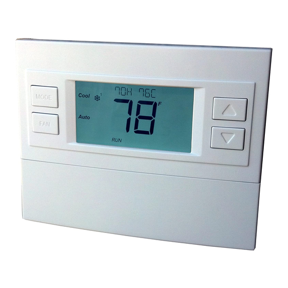
Model TBZ48
Battery Powered Z-Wave Thermostat
1 stage heating and cooling
2 stage heating and cooling
1 stage heating and cooling
2 stage heating and cooling
2
nd
or 3
rd
stage Auxiliary heating (heat strips)
®
Network
Page 1
Advertisement
Table of Contents

Related Manuals for RCS TBZ48


Summary of Contents for RCS TBZ48
-
Page 1: Installation Guide
Installation Guide Model TBZ48 Battery Powered Z-Wave Thermostat This thermostat is compatible with most HVAC systems, including the following: 24VAC systems Note: requires both the R and C wires unless battery powered. • • Standard gas/oil/electric heating systems 1 stage heating and cooling 2 stage heating and cooling •... - Page 2 Caution. Don’t let the wires slip into the wall. *Note: the C wire (24V common) may Take a not be present. Picture! If there is no C wire, the TBZ48 must be powered by batteries. If the C wire is present, you can power the thermostat without batteries Mark the wires according to the terminal markings.
- Page 3 NOTE! If there are separate RC and RH wires, CUT the internal RC=RH jumper on the back of the thermostat circuit board. See picture below. RC=RH JUMPER Cut jumper to allow connection of separate RC and RH wires. Single Stage Heat Pump HVAC System Wiring to the Thermostat Connect the wires as marked from the HVAC system to the corresponding terminals on the thermostat back.
-
Page 4: Mount The Thermostat
Mount the thermostat Install the thermostat on to the base. Install the batteries if the thermostat is not 24VAC powered (no common C wire). 72H 80C MODE Auto Open the front door and install 2 or 4 AA alkaline batteries. Turn on the power at the HVAC system or breaker panel. -
Page 5: Standard Gas/Electric Hvac System Wiring
Standard Gas/Electric HVAC System Wiring Standard HVAC System Typical thermostat wiring colors. Thermostat Connection Caution: verify that original wiring Blue matches. Colors may be different. C 24VAC Common R 24VAC Return White W1 Heat Stage 1 Orange W2 Heat Stage 2 Green G Fan Yellow... -
Page 6: Heat Pump Hvac System Wiring
Heat Pump HVAC System Wiring Heat Pump HVAC System Thermostat Connection Typical thermostat wiring colors. Blue Caution: verify that original wiring C 24VAC Common matches. Colors may be different. R 24VAC Return White W1 Aux Heat Orange Changeover Valve Green G Fan Yellow Y1 Compressor Stage 1... -
Page 7: Thermostat Setup
Thermostat Setup The thermostat must be setup for the correct system type and configuration of the HVAC system for proper operation. Preset HVAC System settings The thermostat is preset for the following typical HVAC system configuration: • HVAC system type: Standard gas/electric •... -
Page 8: System Type
Thermostat Menu Screen Menu choices are displayed in the Status Display Line. Press “Select” to SETUP enter the selected Use the Up/Down MODE Select menu buttons to change to the desired Press “Done” to menu item, then Done exit back to the press “Select”... -
Page 9: Fan Type (For Standard Hvac Systems Only)
Fan Type (For Standard HVAC systems only) Fan type depends on the heating system type. For Gas heat: select “GAS”. This is the default setting. • • For Electric heat: use the Up/Dn arrows to change to “ELECTRIC”. • Press Select to set •... - Page 10 Test Mode Range Y or N Default: N Test mode shortens the system built-in delays (like MOT and MRT) Y= Test mode on. Reduces all delays to 10 sec for quicker system testing N= Test mode off. Normal system delays Aux Heat Enable (Heat Pump Systems only) Range: Y or N Default: Y...
-
Page 11: Z-Wave Installation
Aux Heat On Threshold Range: 3 to 8 degrees Default: 3 Sets the delta from setpoint that stage 3 heating starts. Aux Heat Off Threshold Range: 0 to 7 degrees Default: 0 Sets the delta from setpoint that stage 3 heating stops. Stage 3 turns off at setpoint + Delta Stage 3. -
Page 12: Main Thermostat Screen
Operation Guide Model TBZ48 Battery Powered Z-Wave Thermostat Main Thermostat Screen Backlit Display Text Display Line Room Temperature Temperature Setting 72H 80C Heating/Cooling Warmer MODE Mode Selection Cooler Fan Mode Auto Selection Battery Compartment Flip down door 2xAA or 4xAA Alkaline Batteries... -
Page 13: Setting The System Mode
Staging Indicators “1” = Stage 1 heating or cooling is ON “2” = Stage 2 heating or cooling is ON “3” = Stage 3 heating (Aux Heat) is ON For Heat Pump systems only: “Heat-E” = Emergency heat mode active Setting the System Mode 72H 80C MODE... -
Page 14: Setting The Heating Or Cooling Temperature Setpoint
Setting the Heating or Cooling Temperature Setpoint 72H 80C MODE Press either Up or Down arrow button to go to the Auto Setpoint Change screen Setpoint Change screen Press the Up or Down arrow buttons to set the desired Setpoint being changed temperature setpoint Set to Heat... -
Page 15: Setting The Fan Mode
Setting the Fan Mode 72H 80C MODE Auto Press the FAN button to change the Fan mode Fan Modes: • Auto: Fan automatically operated by the HVAC system. (normal setting) On: Manual Fan mode. Fan stays on until mode is changed back to Auto, •... -
Page 16: Menu Mode Options
Thermostat Menu Mode The Thermostat has a menu of setup and information displays. To change to the Menu Mode, press and hold the FAN button for 5 seconds. The display will change to the Menu Mode and display the Setup screen. Use the Up/Down arrow buttons to scroll through other menu items. -
Page 17: Setup Menu
SETUP Menu User preference settings. FAHRENHEIT OR CELSIUS. Select the temperature display mode. BACKLIGHT TIMEOUT. Sets the time from last button press that the backlight will turn off. Range:10-30 seconds. Note: long backlight timeouts will reduce battery life. If the thermostat is powered from 24VAC, the backlight timeout can be set to “0” which will keep the backlight on continuously. -
Page 18: Thermostat Operation
INFO Menu The INFO menu displays information about the thermostat. Use the Up/Dn buttons to scroll through the various items. Thermostat information displayed: VERSION Thermostat firmware version ZWAVE Z-Wave firmware version NODE ID Z-Wave Node ID HOME ID Z-Wave Home ID SYSTEM TYPE displays current System Type setting (Standard or Heat Pump) If System Type = Standard FAN TYPE displays current Fan Type setting... -
Page 19: Z-Wave® Operation
Caution! Once installed in a Z-Wave network, if you change how the thermostat is powered (from batteries to 24VAC or vice versa), you must remove and re-enrolled the thermostat in the Z-Wave network for it to work correctly. Adding the Battery-Powered Thermostat Model TBZ48 to your ADT Pulse Wireless Network ®... - Page 20 Click the System tab then click the Manage Devices button. In the Manage Devices Assistant, click Lights, Thermostats & more. Select the RCS Battery-Powered Thermostat Model TBZ48 from the drop-down list, then click the Continue button. DCN: 140-02121-06 Page 20...
- Page 21 Follow the instruction shown on the Z-Wave Assistant to complete enrolling the Thermostat. Press and hold the FAN button on the Thermostat until the screen changes to the Menu screen. Press the UP button until ZWAVE is shown in the Status Display line then press Select.
-
Page 22: Reset Device
Reset Device Should the thermostat need to be un-enrolled (removed) from another Z-Wave ® network, follow the “Reset Device” instructions on the ADT Pulse portal. When the portal instructs you to press and release the “include” button as shown above, follow these steps: Press and hold the FAN button for 3 seconds until the Menu screen is displayed. - Page 23 FCC/IC INFORMATION TO USER This device complies with Part 15 of the FCC Rules. Operation is subject to the following two conditions: (1) This device may not cause harmful interference, and (2) This device must accept any interference received, including interference that may cause undesired operation.
Need help?
Do you have a question about the TBZ48 and is the answer not in the manual?
Questions and answers