
Related Manuals for TREND PRT


Summary of Contents for TREND PRT
- Page 1 ORIGINAL INSTRUCTIONS Please read these instructions before use. Failure to follow the warnings and instructions may result in electric shock, fire and/or serious injury.
-
Page 2: Table Of Contents
Definitions: Safety Guidelines Dear Customer Thank you for purchasing this Trend product, The definitions below describe the level of we hope you enjoy many years of creative and severity for each signal word. Please read the productive use. manual and pay attention to these symbols. -
Page 3: Technical Data
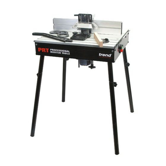
ROUTER TABLE INTENDED USE The unit is intended for stationary operation of portable routers for the cutting of wood or wood TECHNICAL DATA based material when suitable cutter is fitted. Voltage UK & Eire 230/115 It is not intended for continuous production or production line use. -
Page 4: Safety
SAFETY 5. Consider working environment. Do Keep cord from heat, oil and sharp edges. Always trail the power cord not use the product in the rain or in WARNING: away from the work area. a damp environment. Keep work area well lit. Do not use power tools Observe the safety regulations in the 18. -
Page 5: Safety
Recommended speeds ensure there is sufficient clearance spanner or key and to the torque are shown in the Trend Routing between cutter tip and inside edge value provided by the manufacturer. Catalogue and/or website. -
Page 6: Electrical Safety
If you are in doubt, contact an authorised for the power input of this tool (see technical Trend repair agent or a qualified electrician. data). The minimum conductor size is 1.5mm ■ Disconnect the plug from the supply. -
Page 7: Ec Declaration Of Conformity
Pushstick is made in compliance with Harmonized Standard EN 1870-19:2013. Date Code Position For more information please contact Trend at the The year of manufacture is on a label next to the following address or refer to back of manual. -
Page 8: Items Enclosed
ITEMS ENCLOSED... -
Page 9: Description Of Parts
DESCRIPTION OF PARTS Table top Insert rings Back fence Scale Dust port Side pressure guard Top pressure guard Fence cheek Guard Pivot guard lock Floor legs Bench legs Lead on pin Router trigger lock strap Mitre fence Lead on pin park Pushstick Mitre fence slot Back fence slots/keyhole... -
Page 10: Assembly Fitting Legs
ASSEMBLY Fitting Legs WARNING: Prior to assembly and adjustments always unplug the router table. The router table does not need to be secured to the floor or bench. -
Page 11: Router Compatibility
Router Compatibility See machine screw illustrations on next page. Three machine screws (B) are supplied as standard with the PRT table. Make Router Model Screw x Qty TREND T3, T4, T5 B X 2 TREND T10◆, T11◆ B X 3... -
Page 12: Mounting Router To Insert Plate
For Non Trend Routers ■ Mark the centre of the holes onto the base. For users who choose to fit other makes and ■ Remove middle extrusion and mark the centre of models of router, the router base plate and/or the holes with a centre punch. -
Page 13: Fitting Insert Rings
WARNING: Always ensure insert rings are a tight fit in the insert plate. Replace damaged or loose rings immediately. 16mm 20mm 31mm 35mm 50mm 54mm SCALE 68mm 72mm 75mm 90mm -11-... -
Page 14: Fitting Back Fence
Fitting Back Fence Back Fence Vertical Adjustment Use a slotted screwdriver. -12-... -
Page 15: Fitting Top Guard & Top Pressure
Fitting Top Guard & Top Pressure SCALE 10mm max. SCALE SCALE SCALE max. max. SCALE SCALE -13-... -
Page 16: Fitting Side Pressure
Fitting Side Pressure Position 1 Position 2 70mm Position 3 -14- -14-... -
Page 17: Fitting Mitre Fence
Fitting Mitre Fence Mitre Fence Adjustment Preset mitre fence angles can be zeroed by loosening the lock nuts on the underside of the protractor using an 8mm A/F spanner, and adjusting the screws using a Pozi ® No.2. screwdriver. Once set tighten the nuts with an 8mm A/F spanner. Bench Leg Foot Adjustment The back left bench leg has a height adjustment facility. -
Page 18: Fitting Dust Extraction Hose
Fitting Dust Extraction Hose Accessory Ref. CRT/4 (not included) CRT/4 57mmø -16-... -
Page 19: Operation
OPERATION No-Volt Release Switch ■ Plug machine into trailing socket. ■ Put plug of switch into mains supply. ■ Switch on router ■ Press green button to switch on. To switch off press red button. WARNING: Isolate from power supply when making any adjustments. -
Page 20: Back Fence Adjustment
Back Fence Adjustment ■ Adjust back fence position by loosening two knobs (A) and pushing fence forwards or backwards. ■ Lock fence position by tightening the two knobs (A). ■ To adjust fence cheeks loosen max. max. four back knobs (B). Slide cheeks in and out to suit cutter. -
Page 21: Edge Moulding And Grooving
Edge Moulding and Grooving ■ Isolate from power source. ■ Fit cutter. ■ Set back fence position. ■ Set top and side pressures. ■ Fit guard. ■ Check all knobs are tight. ■ Plug into power supply. ■ Switch on. ■... -
Page 22: Stopped Moulding
Stopped Moulding ■ Isolate from power supply. ■ Fit cutter. ■ Set back fence position. Fit some stops to back fence using cramps. ■ Fit guard. ■ Check all knobs are tight. ■ Plug into power supply. ■ Switch on. ■ Drop material against infeed stop A and pivot into cutter. -
Page 23: Mitre Fence & Lead On Pin
Mitre Fence ■ Isolate from power supply. ■ Fit cutter. ■ Adjust angle of mitre fence by loosening knob and turning protractor head to line up angle required with arrow. ■ Place component onto mitre fence. ■ Plug into power supply. - Page 24 Lead-on Pin ■ Isolate from power supply. ■ Fit lead-on pin into threaded hole using a slotted screwdriver. ■ Move back fence back. ■ Fit self guided cutter. ■ Fit top guard. ■ Plug into power supply. ■ Support component onto the lead-on pin and swing into cutter and contact bearing guide.
-
Page 25: Accessories
ACCESSORIES Please use only Trend original accessories. T11 Quick Release Kit Ref. T11/JT/KIT A kit that allows the T11 router to be quickly fitted PRT Table Top View and removed from the PRT. Rear Left Right Quick Raiser handle hole Hose and Connector Ref. -
Page 26: Maintenance
Please call Trend Customer Services for advice as to how to dispose of unwanted Trend electrical products in an environmentally safe way or visit www.trend-uk.com Business User Please call Trend Customer Services for disposal of unwanted Trend electrical products. -
Page 27: Spare Parts - Spare Parts List
Please use only Trend original spare parts. PRT - SPARE PARTS LIST V3.0 04/2018 Qty. Desc. Ref. Extrusion Top Middle WP-PRT/01 Back Fence Complete WP-PRT/02 Extrusion Side Front WP-PRT/03 Extrusion Side Back WP-PRT/04 Extrusion Top Front WP-PRT/05 Extrusion Side Right... -
Page 28: Spare Parts List
PRT - SPARE PARTS LIST V3.0 04/2018 Qty. Desc. Ref. Cam Lever Lock Bush 12mm WP-PRT/43 Pushstick Park Screw M4 x 20mm Pozi WP-PRT/44 Lead-On Pin M6 WP-PRT/45 Pushstick Park Bush WP-PRT/46 Cam Lever Set Screw M8 x 60mm WP-PRT/47... -
Page 29: Spare Parts Diagram
PRT - SPARE PARTS DIAGRAM V3.0 04/2018 -27-... -
Page 30: Spare Parts Diagram
PRT - SPARE PARTS DIAGRAM V3.0 04/2018 -28-... - Page 32 RECYCLABLE © Copyright Trend 2011, 2015, 2018. No part of this publication may be reproduced, stored or transmitted in any form without prior permission. Our policy of continuous improvement means that specifications may change without notice. Trend Machinery and Cutting Tools cannot be held liable for any material rendered unusable or any form of consequential loss. E&OE...
Need help?
Do you have a question about the PRT and is the answer not in the manual?
Questions and answers