Table of Contents
Advertisement
Advertisement
Table of Contents

Related Manuals for Yaesu M-1


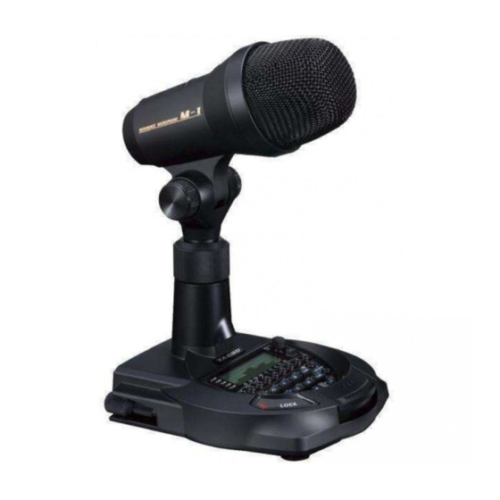
Summary of Contents for Yaesu M-1
-
Page 2: Table Of Contents
Contents General Description ......1 SCOPE key .........10 Safety Precautions ......2 MONITOR Volume knob .....10 Controls & Connections ....4 POWER Switch ........11 PTT key ..........4 DC IN 5V Jack........11 LOCK key ..........4 PHONES Jack........11 MIC ............5 RX AUDIO IN Jack ......12 Angle adjustment knobs ......5 MIC Jack ..........12 Cannon ( XLR ) Microphone Connector ...12... -
Page 3: General Description
Stored settings ( Memories 1 and 2 ) can be accessed instantly. A through ( flat ) preset is also provided. By blending the two microphone outputs togeth- er, you can create your own unique tonal quality. The M-1 adds a new level to the audio creative process. -
Page 4: Safety Precautions
This may result in fire, liquid leak, overheat- This may result in fire, liquid leak, overheat- ing, damage, ignition and equipment fail- ing, breakage, ignition etc. ure. Please contact our company amateur customer support or the retail store where you purchased the device. M-1 Operating Manual... - Page 5 Failure to do so could result in injury, etc. on the power. Failure to do so may cause hearing disor- Do not use products other than those ders. specified by Yaesu. Doing so may result in malfunction. M-1 Operating Manual...
-
Page 6: Controls & Connections
Operation of the PTT key is disabled when the LOCK key is operated. r The LOCK key indicator lights up red when the LOCK key is in operated. M-1 Operating Manual... -
Page 7: Mic
Turn the compression ring clockwise to tighten it and hold the mi- crophone in place. r The stand can be extended a maximum of 6 M-1 Operating Manual... -
Page 8: Display
Bass • • • • • • • • • • • • • • • • • • • • • • • • Treble à r Settings emphasizing the low range are factory preset into memory 1, Settings emphasizing the high range are factory preset into memory 2. Memory 1 Memory 2 M-1 Operating Manual... -
Page 9: Dual Key
[ C ] key: Switches to the condenser microphone ([ C ] LED lights up red ) [ D ] key: Switches to the dynamic microphone ([ D ] LED lights up red ) r When the DUAL key is pressed, the two microphones operate simultaneously. M-1 Operating Manual... -
Page 10: Equalizer Memory Keys
Controls & Connections Equalizer memory keys When the [ 1 ] or [ 2 ] key is pressed, the audio signal output from the M-1 mi- crophone is tailored to the frequency characteristics stored in the respective memory. Condenser microphone memory... -
Page 11: Lc ( Low Cut ) Key
Playback ( Automatically Transmit the Recorded Message ) 1. Turn the Microphone OFF. NOTE: when the M-1 POWER switch is set to “AUTO”, The M-1 power will turn ON/OFF in conjunction with the power switch on the transceiver. 2. Press and hold in the [ ] key while turning the Microphone ON. -
Page 12: Scope Key
The [ SCOPE ] key lights up orange when the real-time audio scope is displayed, and is off when the equalizer is displayed. MONITOR Volume knob The Monitor Volume Knob adjusts the level of the audio in the headphones connected to the PHONES terminal on the rear panel. M-1 Operating Manual... -
Page 13: Power Switch
⑥ POWER Switch Position this switch for the desired operation of the M-1 power. AUTO: The M-1 power turns ON/OFF together with the power of the radio. The M-1 power is always ON. DC IN 5V Jack Use the included power cable to connect to the included AC adapter. -
Page 14: Rx Audio In Jack
If the transceiver microphone jack is an 8-pin terminal, connect the microphone cable to the M-1 microphone’s modular terminal. r If the transceiver microphone jack is a modular connecter, connect the micro- phone cable to the M-1 microphone’s 8-pin terminal. MIC GND MIC GND... -
Page 15: Ptt Key Operation Selector Switch
If the transceiver audio output level is too high, move this switch to ON. The audio signal input to the rear panel RX AUDIO IN terminal will be attenuat- ed by 20dB. Normally use the M-1 with this switch set to OFF. The input audio signal is attenuated. -
Page 16: Convenience Functions
Setting the Display Contrast 1. Turn the Microphone OFF. NOTE: when the M-1 POWER switch is set to “AUTO”, The M-1 power will turn ON/ OFF in conjunction with the power switch on the transceiver. 2. Press and hold in the [ LC ] key while turning the Microphone on. -
Page 17: Reset
NOTE: when the M-1 POWER switch is set to “AUTO”, The M-1 power will turn ON/ OFF in conjunction with the power switch on the transceiver. 2. Press and hold in the [ C ] and [ D ] keys while turning the M-1 Microphone r Once the Microphone comes on, release the keys. -
Page 18: Of The Microphone
100 mVrms ( TYP ) Dimensions ( WxHxD ) : 5.5” x 11.0” x 6.0” ( 140 x 280 x 152 mm ) *H: Maximum with microphone flat Weight ( approx ) : 2.11 lbs ( 960 g ) w/o cable M-1 Operating Manual... -
Page 19: Declaration Of Conformity
Fax: +44 (0)1962 856801 Email: sales@yaesu.co.uk Declaration of Conformity Nr. YUK-DOC-1001-16 We, Yaesu UK Ltd. certify and declare under our sole responsibility that the following equipment complies with the essential requirements of the Directive 1999/5/EC and 2011/65/EU. Type of Equipment Reference Microphone... - Page 20 YAESU MUSEN CO., LTD. Tennozu Parkside Building 1610L-AO-1 2-5-8 Higashi-Shinagawa, Shinagawa-ku, Tokyo 140-0002 Japan YAESU USA Printed in Japan 6125 Phyllis Drive, Cypress, CA 90630, U.S.A. YAESU UK Unit 12, Sun Valley Business Park, Winnall Close Winchester, Hampshire, SO23 0LB, U.K.
Need help?
Do you have a question about the M-1 and is the answer not in the manual?
Questions and answers