Advertisement
Quick Links
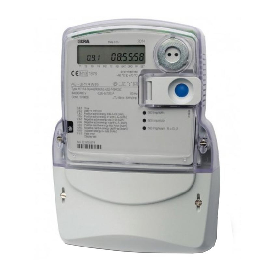
MT174 - Electronic three-phase
time-of-use electricity meters
The MT174 electronic three-phase meters are
designed for measurement and registration of
active,
reactive
and
demand in three-phase four-wire networks. They
can be connected directly to the network. The
metering and technical properties of the meters
comply with the EN 50470-1 and -3 European
standards for active energy meters, classes A
and B, as well as with the IEC 62053-21 and IEC
62052-11 international standards for electronic
meters of active energy for classes 1 and 2, and
optionally with the IEC 62053-23 international
standard for electronic meters of reactive energy
for classes 2 and 3.
apparent
energy
and
Energy Measurement and Management
MT174
Three-Phase Static Electricity
Multi Tariff Meter
with Maximum Demand Indicator
and Load-profile
MT174 -
Electronic three-phase electricity
meters with maximum demand and LP
A built-in time-switch complies with the IEC
62054-21 and IEC 62052-21 standards. It enables
energy registration in up to four tariffs.
The meter software complies with WELMEC 7.2
Issue 1 Software Guide (Measuring Instruments
Directive 2004/22/EC).
The MT174 meters are designed for mechanical
environment M1, electromagnetic environment
E2 and climatic environment -40°C ... +60°C,
relative humidity 95% non-condensing, closed
location. The meters can be installed in any
position.
The meters are designed and manufactured in
compliance with the ISO 9001 (2000) standard.
Advertisement

Related Manuals for ISKRAEMECO MT174


Summary of Contents for ISKRAEMECO MT174
- Page 1 Directive 2004/22/EC). metering and technical properties of the meters comply with the EN 50470-1 and -3 European The MT174 meters are designed for mechanical standards for active energy meters, classes A environment M1, electromagnetic environment and B, as well as with the IEC 62053-21 and IEC E2 and climatic environment -40°C ...
- Page 2 Energy Measurement and Management Terminal block for direct connected meters The terminal block for direct connected meters contains current terminals, auxiliary terminals and potential links for power supply of the voltage metering circuitry. Terminal block of direct connected meters 1. Current terminals 3.
- Page 3 1. Detector of terminal 2. Phase voltage test cover opening contacts b. Potential links under meter cover Terminal blocks of direct connected meters for Imax = 85 A 1. Detector of terminal cover opening 2 . Phase voltage test 3. Sliding potential links (opened contacts) contacts Potential links in the terminal block of direct connect meters for Imax = 120A...
- Page 4 Terminal block for CT operated meters The CT operated meters have separate voltage terminals (Fig. 5, item 2) in the terminal block. They are used supplying voltage metering circuitry. The voltage terminals are equal to the current terminals (Fig. 5, item 1). The current and voltage terminals are made of solid brass with a 5 mm bore diameter;...
- Page 5 The meter connection diagram is stuck on the inner side of the terminal block cover or is printed on the meter nameplate. The meters can be connected in three-phase four- or three-wire networks, as well as in a single-phase two-wire network. a. Connection diagrams of direct connected meters MT174 b. Connection diagram of CT operated meter MT174...
-
Page 6: Meter Installation
METER INSTALLATION 1. Check if voltage and maximum current printed on the meter name plate correspond to the voltage on the network and to the current which will flow through the meter. 2. Fix the meter with three screws to the measuring place. 3. -
Page 7: Data Display
(last three flags on the right side) The MT174 meters enable indication of many different alarms but only four of them can be displayed on the LCD. If more than four alarms are to be indicated on the LCD, one signal flag can be used for two different... - Page 8 The signal flags from left to right have the following functions: FLAG STATUS MEANING Active first tariff Active second tariff Active third tariff Active fourth tariff Terminal cover has been opened (option) Meter cover has been opened (option) Field detector (meter has been tampered with a permanent...
-
Page 9: Display Testing
The emitted pulse rate depends on the meter version and load current. Meter version Meter constant 500 imp/kWh Direct connected 120 A (500 imp/kVAh (D2) 500 imp/kvarh) 1.000 imp/kWh Direct connected 85 A (1.000 imp/kVAh (D1) 1.000 imp/kvarh) 10.000 imp/kWh CT operated (10.000 imp/kvarh, (T1) - Page 10 MANUAL DATA DISPLAY Data are displayed on request as follows. The meter is set to the display testing mode. During the LCD test, the blue pushbutton is pressed for a short time (Tp <2 s). The Std dAtA title is displayed. In this way a menu for selecting data display on request is entered.
-
Page 11: Pulse Output
(active and reactive energy meter for one energy flow direction or active energy meters for two energy flow directions) can be built into the MT174 meters. Note: Pulse output(s) are not available, if the meter is equipped with tariff output(s). - Page 12 Fig. 18: A typical residential solar installation produce broad frequency disturbance signals ranging from the low frequency harmonics to The three-phase electricity meter of type MT174 conductive radiated electromagnetic complies with the requirements of the »Leitfaden interference in the MHz range.
Need help?
Do you have a question about the MT174 and is the answer not in the manual?
Questions and answers