Table of Contents
Advertisement
Quick Links
Advertisement
Table of Contents

Related Manuals for Advantech ARK-3360


Summary of Contents for Advantech ARK-3360
- Page 1 User Manual ARK-3360 Box IPC...
- Page 2 ARK-3360 User Manual...
- Page 3 English user manual included as a PDF file on the CD. Please disregard the Chinese hard copy user manual if the product is not to be sold and/or installed in China. ARK-3360 User Manual...
- Page 4 The documentation and the software included with this product are copyrighted 2010 by Advantech Co., Ltd. All rights are reserved. Advantech Co., Ltd. reserves the right to make improvements in the products described in this manual at any time without notice.
-
Page 5: Declaration Of Conformity
Because of Advantech’s high quality-control standards and rigorous testing, most of our customers never need to use our repair service. If an Advantech product is defec- tive, it will be repaired or replaced at no charge during the warranty period. For out- of-warranty repairs, you will be billed according to the cost of replacement materials, service time and freight. -
Page 6: Technical Support And Assistance
Technical Support and Assistance Visit the Advantech web site at www.advantech.com/support where you can find the latest information about the product. Contact your distributor, sales representative, or Advantech's customer service center for technical support if you need additional assistance. Please have the following information ready before you call: –... -
Page 7: Ordering Information
Plug, 0 ~ 40° C for Home and Office Use 1700001947 Power cable 2-pin 180 cm, USA for ARK-338X 1700001948 Power cable 2-pin 180 cm, Europe for ARK-338X 1700001949 Power cable 2-pin 180 cm, UK for ARK-338X 1700009001 2-Pole Phoenix to DC-Jack Power cable ARK-3360 User Manual... -
Page 8: Safety Instructions
RESTRICTED ACCESS AREA: The equipment should only be installed in a Restricted Access Area. DISCLAIMER: This set of instructions is given according to IEC 704-1. Advan- tech disclaims all responsibility for the accuracy of any statements contained herein. ARK-3360 User Manual viii... -
Page 9: Table Of Contents
Ethernet ..................3 Chipset ...................... 3 1.3.1 Functional Specification ..............3 Mechanical Specifications................. 5 1.4.1 Dimensions ................... 5 Figure 1.1 ARK-3360 Mechanical dimension drawing....5 1.4.2 Weight................... 5 Power Requirement .................. 5 1.5.1 System Power................5 1.5.2 RTC Battery .................. 5 Environment Specification................. - Page 10 Figure 3.16MPS Configuration ........... 38 3.3.11 Smbios Configuration ..............39 Figure 3.17Smbios Configuration ..........39 3.3.12 USB Configuration ..............39 Figure 3.18USB Configuration............ 39 Figure 3.19USB Mass storage Device Configuration ....40 Advanced PCI/PnP Settings ..............41 ARK-3360 User Manual...
- Page 11 Load Optimal Defaults ..............48 3.8.4 Load Fail-Safe Defaults .............. 49 Appendix A ARK-3360L COM2 RS422/485 Communication Setting Procedure ARK-3360L COM2 RS422/485 Communication Setting Procedure ..52 Table A.1: Jumper setting of ARK-3360 COM2 mode ....52 ARK-3360 User Manual...
- Page 12 ARK-3360 User Manual...
-
Page 13: Chapter 1 General Introduction
Chapter General Introduction This chapter gives background information on ARK-3360 series. -
Page 14: Introduction
The ARK-3360 answers demands by offering 1 x VGA, 6 x USB 2.0 ports, up to 3 x Giga LAN port and 6 x COM ports; packed into a small rugged unit and powered by an Intel Atom processor. -
Page 15: Ethernet
Supports HD Codec Supports Link for Audio and Telephony CODECS SB: Intel® ICH8M chip supports: USB host interface with support for 6 USB 2.0 ports USB Interface All ports are High-Speed, Full-Speed, and Low-Speed capable Supports legacy keyboard/mouse software ARK-3360 User Manual... - Page 16 10 I/O pins with one 5V power ping and one ground pin 5V tolerance I/Os. DIO Connectors: ARK-3360L: 9 pins DSUB 9 connector ARK-3360F: 10 pins phoenix connector Battery backup BATTERY 3V/210 mAh with WIRE x 1 ARK-3360 User Manual...
-
Page 17: Mechanical Specifications
Mechanical Specifications 1.4.1 Dimensions 264.5 [10.41] x 69.2 [2.72] x 137.25 [5.4] Unit: mm [Inch] Figure 1.1 ARK-3360 Mechanical dimension drawing 1.4.2 Weight 2.2 kg (4.4 lb) Power Requirement 1.5.1 System Power Minimum power input: – ARK-3360L: DC12 V 3 A –... -
Page 18: Environment Specification
When system is equipped with Compact Flash card only: 50G, IEC 60068-2-27, half sine, 11 ms duration. When system is equipped with 2.5-inch: 20G, IEC 60068-2-27, half sine, 11 ms duration. 1.6.6 Safety UL, CCC, BSMI 1.6.7 CE, FCC, CCC, BSMI ARK-3360 User Manual... -
Page 19: Chapter 2 H/W Installation
Chapter H/W Installation This chapter introduces external IO and the installation of ARK-3360 hardware. -
Page 20: Introduction
2.2.1 Jumper Description You may configure the ARK-3360 to match the needs of your application by setting jumpers. A jumper is a metal bridge used to close an electric circuit. It consists of two metal pins and a small metal clip (often protected by a plastic cover) that slides over the pins to connect them. -
Page 21: Jumper List
JP1, JP2, JP3 COM3 type select JP4, JP5, JP6 COM4 type select COM5 type select COM6 type select JP9, JP10 COM2 type select 2.2.3 Jumper Location At Mother Board Figure 2.1 Jumper and connector layout (Mother Board) ARK-3360 User Manual... -
Page 22: Jumper Setting
PIN HEADER 3*1P 180D(M) 2.0mm SMD SOUARE PIN Setting Function (1-2) RS232 (default) (3-4) RS485 (5-6) RS422 ATX / AT Mode switch Part Number 1653002101 Footprint HD_3x2P_79_D Description PIN HEADER 2*1P 180D(M)SQUARE 2.0mm DIP W/O Pb Setting Function ATX Mode AT Mode (default) ARK-3360 User Manual... - Page 23 PIN HEADER 3*2P 180D(M) 2.54mm DIP W/O Pb Setting Function JP4 (1-3, 2-4) JP5 (1-3, 2-4) RS-232 (Default) JP6 (5-6) JP4 (3-5, 4-6) JP5 (3-5, 4-6) RS-422 JP6 (3-4) JP4 (3-5, 4-6) JP5 (3-5, 4-6) RS-485 JP6 (1-2) ARK-3360 User Manual...
- Page 24 COM2 Type Select (Link with JP10 and MB-J2) Part Number 1653003200 Footprint HD_3x2P_100_D Description PIN HEADER 3*2P 180D(M) 2.54mm DIP W/O Pb Setting Function JP9 (1-3, 2-4) RS-232 (Default) JP10 (1-3, 2-4) JP9 (3-5, 4-6) RS422/485 JP10 (3-5, 4-6) ARK-3360 User Manual...
-
Page 25: Connectors
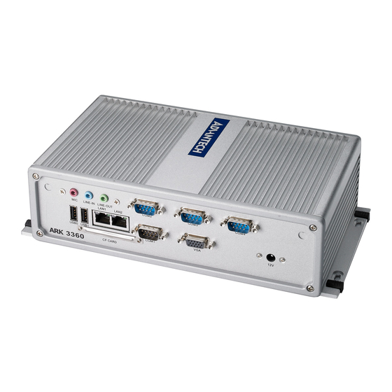
Connectors 2.3.1 ARK-3360 External I/O Connectors ARK-3360L: Figure 2.3 ARK-3360L IO connectors drawing ARK-3360 User Manual... -
Page 26: Figure 2.4 Ark-3360F Io Connectors Drawing
Figure 2.4 ARK-3360F IO connectors drawing 2.3.1.1 COM Connector ARK-3360 provides maximum six D-sub 9-pin connectors, which offers RS-232/422/ 485 serial communication interface ports. Default setting is RS-232, if you want to use RS-422/485, you can find the jumper installation in Chapter 2.2.4. -
Page 27: Table 2.3: Com Connector Pin Assignments
2.3.1.2 Ethernet Connector (LAN) ARK-3360 is equipped up to three Ethernet controllers that are fully compliant with IEEE 802.3u 10/100/1000 Mbps CSMA/CD standards. LAN1 is equipped with 82567; LAN1 is equipped with 82583V; and LAN3 is equipped with 82541PI. The Ethernet port provides a standard RJ-45 jack connector with LED indicators on the front side to show its Active/Link status (Green LED) and Speed status (Yellow LED). -
Page 28: Figure 2.7 Audio Connector
2.3.1.3 Audio Connector ARK-3360 offers stereo audio ports by three phone jack connectors of Line_Out, Line_In, Mic_In. The audio chip is controlled by ALC888, and it’s compliant with Aza- lea standard. Figure 2.7 Audio connector Table 2.5: Audio Connector Pin Assignments 2.3.1.4... -
Page 29: Figure 2.9 Dio Connector (Ark-3360F)
2.3.1.5 USB Connector ARK-3360 provides six USB interface connectors, which give complete Plug & Play and hot swapping for up to 127 external devices. The USB interface complies with USB UHCI, Rev. 2.0 compliant. The USB interface can be disabled in the system BIOS setup. -
Page 30: Figure 2.11Vga Connector
2.3.1.6 VGA Connector The ARK-3360 provides a high resolution VGA interface connected by a D-sub 15- pin connector to support a VGA CRT monitor. It supports display resolution of up to 2048 x 1536 or 1400 x 1050. Figure 2.11 VGA Connector Table 2.9: VGA Connector Pin Assignments... -
Page 31: Installation
Figure 2.14 Power Button 2.3.1.9 LED Indicators There are two LEDs on ARK-3360 front metal face plate for indicating system status: PWR LED is for power status; and HDD LED is for HDD & compact flash disk status. Figure 2.15 LED Indicators Installation 2.4.1... -
Page 32: Figure 2.17Assemble Hdd And Hdd Frame With 4 Screws
Figure 2.17 Assemble HDD and HDD frame with 4 screws Use the HDD damper screws to assemble the HDD door and HDD frame. Figure 2.18 Use the HDD damper screws to assemble the HDD door and HDD frame ARK-3360 User Manual... -
Page 33: Memory Installation
Install the memory module into the SO-DIMM socket at the bottom of the main board. Figure 2.20 Install the memory module into the SO-DIMM socket at the bottom of the Main board Replace HDD door and secure with screws. ARK-3360 User Manual... -
Page 34: Cf Card Installation
2.4.3 CF Card Installation Unscrew the CF door screws. Figure 2.21 Unscrew the CF door screws Pull the CF tray out. Figure 2.22 Pull the CF tray out ARK-3360 User Manual... -
Page 35: Figure 2.23Remove Cf Bracket
Remove the black CF bracket. Figure 2.23 Remove CF bracket Put CF on to the CF tray. Figure 2.24 Put CF onto the CF tray Push the CF tray back and secure with screws. ARK-3360 User Manual... - Page 36 ARK-3360 User Manual...
-
Page 37: Bios Settings
Chapter BIOS Settings This chapter introduces how to set BIOS configuration data. -
Page 38: Entering Bios Setup
AMIBIOS has been integrated into many motherboards for over a decade. With the AMIBIOS Setup program, you can modify BIOS settings and control the various sys- tem features. This chapter describes the basic navigation of the ARK-3360 BIOS setup screens. -
Page 39: Main Menu
MM/DD/YY format. The time must be entered in HH:MM:SS format. Advanced BIOS Features Setup Select the Advanced tab from the ARK-3360 setup screen to enter the Advanced BIOS Setup screen. You can select any of the items in the left frame of the screen, such as CPU Configuration, to go to the sub menu for that item. -
Page 40: Cpu Configuration
This item allows you to limit CPUID maximum value. Execute-Disable Bit Capability This item allows you to enable or disable the No-Execution page protection technology. Hyper Threading Technology This item allows you to enable or disable Intel® Hyper Threading technology. ARK-3360 User Manual... -
Page 41: Ide Configuration
S.M.A.R.T.: Select the smart monitoring, analysis, and reporting technology. – 32Bit Data Transfer: Enables or disables 32-bit data transfer. Hard Disk Write Protect Disable/Enable device write protection. This will be effective only if device is accessed through BIOS. ARK-3360 User Manual... -
Page 42: Super I/O Configuration
This item allows you to select Parallel port IRQ. RS-485 Control for SP2 This item allows you to select RS485 control. Auto Direction Control Select This item allows you to enable or disable auto flow control function. ARK-3360 User Manual... -
Page 43: Hardware Health Configuration
This item allows you to control H/W monitor of showing. Temperature & Voltage Show CPU/System Temperature Vcore / +3.3 Vin / +5 Vin / +12 Vin / VBAT 3.3.5 Secondary SuperI/O Configuration (Only for ARK-3360F) Figure 3.8 Super I/O Configuration ARK-3360 User Manual... -
Page 44: Acpi Settings
RS-485 Control for SP2 This item allows you to select RS485 control. SP 3/4/5/6 Auto Direction Control Select This item allows you to enable or disable auto flow control function. 3.3.6 ACPI Settings Figure 3.9 ACPI Setting ARK-3360 User Manual... -
Page 45: Figure 3.10General Acpi Configuration
Figure 3.10 General ACPI Configuration Suspend Mode Select the ACPI state used for system suspend. Report Video on S3 Resume This item allows you to invoke VA BIOS POST on S3/STR resume. 3.3.6.2 Advanced ACPI Configuration Figure 3.11 Advanced ACPI Configuration ARK-3360 User Manual... - Page 46 Allows you to configure Intel's Energy Lake power management technology. APIC ACPI SCI IRQ Enable/Disable APIC ACPI SCI IRQ. USB Device Wakeup From S3/S4 Enable/Disable USB Device Wakeup from S3/S4. High Performance Event Timer Enable/Disable High performance Event timer. ARK-3360 User Manual...
-
Page 47: Ahci Setting
Figure 3.13 AHCI Setting AHCI Port0 / Port While entering setup, BIOS auto detects the presence of IDE devices. This dis- plays the status of auto detection of IDE device. 3.3.8 APM Configuration Figure 3.14 APM Configuration ARK-3360 User Manual... -
Page 48: Event Log Configuration
Enable / Disable RI to generate a wake event. Resume On PME# Enable / Disable PME to generate a wake event. Resume On RTC Alarm Enable / Disable RTC to generate a wake event. 3.3.9 Event Log Configuration Figure 3.15 Event Log Configuration ARK-3360 User Manual... -
Page 49: Mps Configuration
Mark all events as read Mark all unread events as read. Clear Event Log Discard all events in the event Log. 3.3.10 MPS Configuration Figure 3.16 MPS Configuration MPS Revision This item allows you to select MPS reversion. ARK-3360 User Manual... -
Page 50: Smbios Configuration
3.3.11 Smbios Configuration Figure 3.17 Smbios Configuration Smbios Smi Support SMBIOS SMI wrapper support for PnP function 50h-54h. 3.3.12 USB Configuration Figure 3.18 USB Configuration ARK-3360 User Manual... - Page 51 Emulation Type If Auto, USB devices less than 530MB will be emulated as Floppy and remaining as hard drive. Force FDD option can be used to force a FDD formatted drive to boot as FDD (Ex. ZIP drive). ARK-3360 User Manual...
-
Page 52: Advanced Pci/Pnp Settings
Advanced PCI/PnP Settings Select the PCI/PnP tab from the ARK-3360 setup screen to enter the Plug and Play BIOS Setup screen. You can display a Plug and Play BIOS Setup option by highlighting it using the <Arrow> keys. All Plug and Play BIOS Setup options are described in this section. -
Page 53: Boot Settings
When set to Reserved will specified DMA will Reserved for use by leg- acy ISA devices. Reserved Memory Size This item allows you to reserved size of memory block for legacy ISA device. Boot Settings Figure 3.21 Boot Setup Utility ARK-3360 User Manual... -
Page 54: Boot Settings Configuration
Wait for the F1 key to be pressed if an error occurs. Hit “DEL” Message Display Displays - Press DEL to run Setup in POST. Interrupt 19 Capture This item allows option ROMs to trap interrupt 19. ARK-3360 User Manual... -
Page 55: Security Setup
Security Setup Figure 3.23 Password Configuration Select Security Setup from the ARK-3360 Setup main BIOS setup menu. All Security Setup options, such as password protection and virus protection are described in this section. To access the sub menu for the following items, select the item and press <Enter>:... -
Page 56: Advanced Chipset Settings
North Bridge Chipset Configuration Figure 3.25 North Bridge Configuration DRAM Frequency This item allows you to manually changed DRAM frequency. Configure DRAM Timing by SPD This item allows you to enables or disables detect by DRAM SPD. ARK-3360 User Manual... - Page 57 Boot Display Device Select boot display device at post stage. Flat Panel Type This item allows you to select which panel resolution you wants. Spread Spectrum Clock This item allows you to enables or disables spread spectrum clock. ARK-3360 User Manual...
-
Page 58: South Bridge Chipset Configuration
Enables or disables GbE LAN wake up from S5 function. HDA Controller Enables or disables the HDA controller. SMBUS Controller Enables or disables the SMBUS controller. SLP_S4# Min. Assertion Width This item allows you to set a delay of sorts. ARK-3360 User Manual... -
Page 59: Exit Os
3.8.3 Load Optimal Defaults The ARK-3360 automatically configures all setup items to optimal settings when you select this option. Optimal Defaults are designed for maximum system performance, but may not work best for all computer applications. In particular, do not use the Opti- mal Defaults if your computer is experiencing system configuration problems. -
Page 60: Load Fail-Safe Defaults
3.8.4 Load Fail-Safe Defaults The ARK-3360 automatically configures all setup options to fail-safe settings when you select this option. Fail-Safe Defaults are designed for maximum system stability, but not maximum performance. Select Fail-Safe Defaults if your computer is experi- encing system configuration problems. - Page 61 ARK-3360 User Manual...
- Page 62 ARK-3360 User Manual...
-
Page 63: Ark-3360L Com2 Rs422/485 Communication Setting Procedure
Appendix ARK-3360L COM2 RS422/485 Communication Setting Procedure... -
Page 64: Ark-3360L Com2 Rs422/485 Communication Setting Procedure
ARK-3360L COM2 RS422/485 Communication Setting Procedure Table A.1: Jumper setting of ARK-3360 COM2 mode COM2 RS232/422/485 Select Part Number 1653003260 Footprint HD_3x2P_79 Description PIN HEADER 3*1P 180D(M) 2.0mm SMD SOUARE PIN Setting Function (1-2) RS232 (default) (3-4) RS485 (5-6) RS422 The default COM2 cable is only for RS-232, if you want to use RS-422/485, please follow the following steps to use RS-422/485. - Page 65 Unscrew the screws to open the top cover, as shown in as shown in the figures below. After remove the top cover, you will find COM2 cable, as shown in the figure below. ARK-3360 User Manual...
- Page 66 Please replace the internal COM2 cable by new cable (Part Number: 1700001967), and adjust jumper 2 (Figure 6). Finally, you can screw the new COM2 cable on the front panel and screw all screws back. ARK-3360 User Manual...
- Page 67 ARK-3360 User Manual...
- Page 68 No part of this publication may be reproduced in any form or by any means, electronic, photocopying, recording or otherwise, without prior written permis- sion of the publisher. All brand and product names are trademarks or registered trademarks of their respective companies. © Advantech Co., Ltd. 2010...
Need help?
Do you have a question about the ARK-3360 and is the answer not in the manual?
Questions and answers