
Related Manuals for NETGEAR ProSAFE S3300


Summary of Contents for NETGEAR ProSAFE S3300
- Page 1 ProSAFE S3300 Smart Switch Hardware I nstalla t ion G ui de August 2014 202-11445-01 350 East Plumeria Drive San Jose, CA 95134...
- Page 2 See the regulatory compliance document before connecting the power supply. Trademarks NETGEAR, the NETGEAR logo, and Connect with Innovation are trademarks and/or registered trademarks of NETGEAR, Inc. and/or its subsidiaries in the United States and/or other countries. Information is subject to change without notice.
-
Page 3: Table Of Contents
Contents Chapter 1 Introduction Hardware Overview ........... 6 Hardware Features . -
Page 4: Appendix A Troubleshooting
S3300 Smart Switch Step 9: Manage the Switch Through a Web Browser or the Smart Control Center Utility........30 Appendix A Troubleshooting Troubleshooting Chart . -
Page 5: Chapter 1 Introduction
Hardware Features • Stacking • Package Contents Note: For more information about the topics that are covered in this manual, visit the support website at support.netgear.com. Note: In this manual, the S3300 Smart Switch is referred to as the smart switch. -
Page 6: Hardware Overview
The 10G/1G ports always operate in full-duplex mode. The maximum segment length is 328 feet (100 meters) over Category 5 unshielded twisted-pair (UTP) cable. For 10GBASE-T connections, NETGEAR recommends that you use a Category 6a cable or a cable that is even higher rated. - Page 7 Two dedicated 10G/1G SFP+ ports. • One USB port to support firmware upgrades from a disk and backups to a storage device. • Full NETGEAR Smart Switch functionality. • Full compatibility with IEEE standards: IEEE 802.3i (10BASE-T) IEEE 802.3u (100BASE-TX) IEEE 802.3ab (1000BASE-T)
-
Page 8: Stacking
S3300 Smart Switch Stacking A single switch can control and manage a stack. This switch is referred to as the stack master, or simply, the master. Any other members in the stack are referred to as slaves. All switches in a stack are stack members. Slaves can download firmware from the master and the master can push firmware to the slaves. -
Page 9: Package Contents
• Power cord • Quick installation guide • Smart switch resource CD with NETGEAR Smart Control Center and a link to the S3300 Smart Switch Software Administration Manual. If any item is missing or damaged, contact the vendor immediately. Introduction... -
Page 10: Chapter 2 Physical Description
Physical Description This chapter describes the S3300 Smart Switch hardware features. The chapter includes the following sections: • S3300-52X and S3300-52X-PoE+ Description • S3300-28X and S3300-28X-PoE+ Description • Device Hardware Interfaces... -
Page 11: S3300-52X And S3300-52X-Poe+ Description
S3300 Smart Switch S3300-52X and S3300-52X-PoE+ Description This section describes the smart switch hardware features for models S3300-52X and S3300-52X-PoE+. S3300-52X Front Panel and Back Panel Configuration The S3300-52X and S3300-52X-PoE+ models provide forty eight 10/100/1000 Mbps ports, two dedicated 100M/1G/10GBASE-T ports, and two dedicated 10G/1G Gbps SFP+ ports. Each port can sense the line speed and negotiate the duplex mode with the link partner automatically. - Page 12 • Serial console port that is configured for 115200, N, 8, 1. The serial port is for debugging purposes by NETGEAR support. (The port requires a special adapter.) • Slot for an optional redundant power supply (RPS, model S3300-52X-PoE+ only).
-
Page 13: Led Designations
S3300 Smart Switch LED Designations This section describes the LED designations of models S3300-52X and S3300-52X-PoE+. Port LEDs The following table describes the RJ-45 and SFP+ port LED designations. Table 1. Port LEDs models S3300-52X and S3300-52X-PoE+ Designation Both Models Left LED •... -
Page 14: S3300-28X And S3300-28X-Poe+ Description
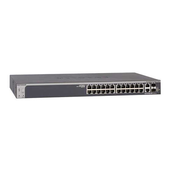
S3300 Smart Switch System LEDs The following table describes the system LED designations. Table 2. System LEDs models S3300-52X and S3300-52X-PoE+ Designation Power LED • Off . Power is not supplied to the smart switch. • Solid green . The smart switch is powered on and operating normally. •... - Page 15 S3300 Smart Switch The following figures illustrate the front panel of models S3300-28X and S3300-28X-PoE+. Power and Fan LEDs Left LEDs: RJ45 SPD Mode LED 10G ports Link/ACT LEDs Right LEDs: nonfunctioning Stack ID LED 10/100/1000 Mbps ports Factory Defaults button SFP+ ports USB port Reset button...
- Page 16 • Serial console port that is configured for 115200, N, 8, 1. The serial port is for debugging purposes by NETGEAR support. (The port requires a special adapter.) • Slot for an optional redundant power supply (RPS, model S3300-28X-PoE+ only).
-
Page 17: Led Designations
S3300 Smart Switch LED Designations This section describes the LED designations of models S3300-28X and S3300-28X-PoE+. Port LEDs The following table describes the RJ-45 and SFP+ port LED designations. Table 3. Port LEDs models S3300-28X and S3300-28X-PoE+ Designation Both Models Left LED •... -
Page 18: Device Hardware Interfaces
S3300 Smart Switch System LEDs The following table describes the system LED designations. Table 4. System LEDs models S3300-28X and S3300-28X-PoE+ Designation Power LED • Off . Power is not supplied to the smart switch. • Solid green . The smart switch is powered on and operating normally. •... -
Page 19: 10Gbase-T Ports
S3300 Smart Switch When you insert a cable into the smart switch’s RJ-45 port, the smart switch automatically performs the following actions: • Senses whether the cable is a straight-through or crossover cable. • Determines whether the link to the attached device requires a normal connection (such as when you are connecting the port to a computer) or an uplink connection (such as when you are connecting the port to a router, switch, or hub). -
Page 20: Usb Port
S3300 Smart Switch To reset the smart switch to factory default settings using the Factory Defaults button: Insert a device such as a straightened paper clip into the opening. Press the recessed Factory Defaults button for about eight seconds. Note: A smart switch that is a member of a stack retains its stacking configuration. -
Page 21: Chapter 3 Desktop And Backbone Switching
Desktop and Backbone Switching The S3300 Smart Switch is designed to provide flexibility in configuring your network connections. You can use the smart switch as your only network traffic distribution device or with 10 Mbps, 100 Mbps, 1000 Mbps, and 10 Gbps hubs and switches. The chapter includes the following sections: •... -
Page 22: Desktop Switching
S3300 Smart Switch Desktop Switching You can use the smart switch as a desktop switch to build a small network that allows users 1000 Mbps access to, for example, a file server. With full duplex enabled, the smart switch port connected to the server or computer can provide 2000 Mbps throughput. If you use a 10 Gbps module to connect the smart switch to the file server in full-duplex operation, the server can provide up to 20 Gbps throughput. -
Page 23: Backbone Switching
S3300 Smart Switch Backbone Switching You can use the smart switch as a backbone switch in a small network that gives users high-speed access to servers and other network devices. The following figure shows a variety of S3300 models. You can use any of the S3300 models for backbone switching. -
Page 24: Chapter 4 Installation
Installation This chapter describes the installation procedures for the S3300 Smart Switch. Switch installation involves the steps described in the following sections: Step 1: Prepare the Site Step 2: Install the Switch Step 3: Check the Installation Step 4: Connect Devices to the Switch Step 5: Install an SFP Transceiver Module Step 6: Install the Smart Switch as a Stack Master or Stack Slave Step 7: Apply AC Power... -
Page 25: Step 1: Prepare The Site
S3300 Smart Switch Step 1: Prepare the Site Before you install the smart switch, ensure that the operating environment meets the site requirements that are listed in the following table. Table 5. Site requirements Characteristics Requirements Mounting • Desktop installations. Provide a flat table or shelf surface. •... -
Page 26: Install The Switch In A Rack
S3300 Smart Switch Install the Switch in a Rack To install the smart switch in a rack, you need the 19-inch rack-mount kit supplied with the smart switch. To install the smart switch in a rack: Attach the supplied mounting brackets to the side of the smart switch. Insert the screws provided in the rack-mount kit through each bracket and into the bracket mounting holes in the smart switch. -
Page 27: Step 3: Check The Installation
S3300 Smart Switch Step 3: Check the Installation Before you apply power to the smart switch, perform the steps that are described in this section. To check the installation: Inspect the equipment thoroughly. Verify that all cables are installed correctly. Check cable routing to make sure that cables are not damaged or creating a safety hazard. -
Page 28: Step 5: Install An Sfp Transceiver Module
The following procedure describes how to install an optional SFP transceiver module into one of the SFP ports of the smart switch. Note: Contact your NETGEAR sales office to buy these modules. If you do not want to install an SFP module, skip this procedure. ... -
Page 29: Step 6: Install The Smart Switch As A Stack Master Or Stack Slave
S3300 Smart Switch Step 6: Install the Smart Switch as a Stack Master or Stack Slave The smart switch can function as a master, backup master, or slave in a stack. (For more information about stacking, see Stacking on page 8.) A backup master runs as a slave. -
Page 30: Step 8: Install The Rps And Apply Rps Dc Power
S3300 Smart Switch To apply AC power: Connect the end of the power cord to the power receptacle on the back of the smart switch. Plug the AC power cord into a power source such as a wall socket or power strip. When you apply power, the Power LED on the smart switch’s front panel lights. - Page 31 Troubleshooting This appendix provides information about troubleshooting the S3300 Smart Switch. The appendix includes the following sections: • Troubleshooting Chart • Additional Troubleshooting Suggestions...
-
Page 32: Troubleshooting Chart
S3300 Smart Switch Troubleshooting Chart The following table lists symptoms, causes, and solutions for possible problems. Table 6. Troubleshooting chart Symptom Cause Solution Power LED is off. No power is received. • Check the power cord connections at the smart switch and the power source. •... -
Page 33: Additional Troubleshooting Suggestions
Switch Integrity. If necessary, verify the integrity of the smart switch by resetting it. To reset the smart switch, disconnect the AC power from the smart switch and then reconnect the AC power. If the problem continues, contact NETGEAR technical support: Phone (US & Canada only): 1-888-NETGEAR. - Page 34 Physical and Technical Specifications This appendix provides the physical and technical specifications for the S3300 Smart Switch. Table 7. Physical and technical specifications Feature Description Network protocols and • IEEE 802.3i (10BASE-T) supported standards • IEEE 802.3u (100BASE-TX) • IEEE 802.3ab (1000BASE-T) •...
- Page 35 S3300 Smart Switch Table 7. Physical and technical specifications (continued) Feature Description Performance and capacity • Forwarding mode: Store and Forward • Stacking for up to six switches • Bandwidth: S3300-52X/S3300-52X-PoE+ models: 176 Gbps S3300-28X/S3300-28X-PoE+ models: 128 Gbps • Address database size: 16K Media Access Control (MAC) addresses •...
- Page 36 S3300 Smart Switch Table 7. Physical and technical specifications (continued) Feature Description Environmental specifications • Operating temperature: 0 to 50°C (32 to 122°F) • Storage temperature: –20 to 70°C (28 to 158°F) • Operating humidity: 10–90% maximum relative humidity, noncondensing •...
Need help?
Do you have a question about the ProSAFE S3300 and is the answer not in the manual?
Questions and answers