Table of Contents
Advertisement
Quick Links
Advertisement
Table of Contents

Related Manuals for Panasonic WJ-HXE400


Summary of Contents for Panasonic WJ-HXE400
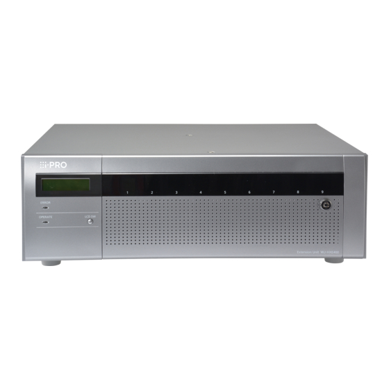
- Page 1 Operating Instructions Extension Unit WJ-HXE400 Model No. WJ-HXE400/G Before attempting to connect or operate this product, please read these instructions carefully and save this manual for future use. The model number is abbreviated in some descriptions in this manual.
-
Page 2: Safety Information
MAINS SWITCH nor an all-all pole circuit breaker, the installation shall be carried out in accordance For U.S. and Canada: with all applicable installation rules. WJ-HXE400 • The connections should comply with local electrical code. For Europe and other countries: WJ-HXE400/G... - Page 3 If you lose the fuse cover the plug must not be used until a replacement cover is obtained. A replacement fuse cover can be purchased from your local Panasonic Dealer. IF THE FITTED MOULDED PLUG IS UNSUITABLE FOR THE SOCKET OUTLET IN YOUR HOME THEN THE FUSE SHOULD BE REMOVED AND THE PLUG CUT OFF AND DISPOSED OF SAFELY.
-
Page 4: Important Safety Instructions
Safety Information (continued) Important safety instructions 1) Read these instructions. 2) Keep these instructions. 3) Heed all warnings. 4) Follow all instructions. 5) Do not use this apparatus near water. 6) Clean only with dry cloth. 7) Do not block any ventilation holes. Install in accordance with the manufacturer’s instructions. 8) Do not install near any heat sources such as radiators, heat registers, stoves, or other apparatus (including amplifiers) that produce heat. -
Page 5: Table Of Contents
Contents Safety Information ........................2 Important safety instructions ..............................4 Introduction ..........................6 Preface ...................................... 6 Standard accessories ................................6 About the user manuals ................................6 Disclaimer of warranty ................................7 About HDD Unit ..................................7 Precautions ..........................8 Precautions for handling ................................9 Precautions for installation .............................. -
Page 6: Introduction
Introduction Preface The WJ-HXE400 is the extension unit for the recorder (WJ-NX400K: as of December, 2016), which is sold separately. The unit can be mounted with a maximum of 9 HDD units (hard disk drive installed in a canister). They can be used as RAID (Redundant Arrays of Inexpensive Disk) to improve fault tolerance of the HDD. -
Page 7: Disclaimer Of Warranty
(continued) Disclaimer of warranty IN NO EVENT SHALL Panasonic Corporation. BE LIABLE TO ANY PARTY OR ANY PERSON, EXCEPT FOR REPLACEMENT OR REASONABLE MAINTENANCE OF THE PRODUCT, FOR THE CASES, INCLUDING BUT NOT LIMITED TO BELOW: (1) ANY LOSS OR DAMAGE, INCLUDING WITHOUT LIMITATION, DIRECT OR INDIRECT, SPECIAL, CONSEQUENTIAL OR EXEMPLARY, ARISING OUT OF OR RELATING TO THE PRODUCT;... -
Page 8: Precautions
Precautions Refer installation work to the dealer. Do not connect to outlets or wiring device if their Installation work requires technique and experiences. Failure ratings are beyond the specified rating. If the rating goes over the specified rating such by putting to observe this may cause fire, electric shock, injury, or dam- age to the product. -
Page 9: Precautions For Handling
The input power source for this product is 120 V AC 60 Hz If this happens, it can cause malfunction. (WJ-HXE400), 220 V - 240 V AC 50 Hz/ 60 Hz (WJ-HXE400/G). Leave it switched off for around 2 hours in the following cases. -
Page 10: Precautions For Installation
• Clear a space of more than 5 cm {2 inches} from both sides, the top, and the rear of the product. Do not block Panasonic assumes no responsibility for injuries or the ventilation holes on the front side since this product... -
Page 11: Major Operating Controls And Their Functions
Major operating controls and their functions Front view ➀ ➁ ➂ ④ ⑤ ⑥ ⑦ ➀ Error indicator [ERROR] ➃ Key hole Blinks when an error that can become a problem for the Use the provided key to open/close the front cover. extension unit to run the system occurs. -
Page 12: Inside The Front Cover
Major operating controls and their functions (continued) Inside the front cover The following illustration shows that 9 HDD units are installed with the "HDD unit holding brackets" removed. ➀ ➁ ➂ ➃ ➄ ➀ HDD units [Option] Lights red: Indicates that the respective hard disk drive Only the hard disk drive encased in the dedicated hard is faulty (which can be recovered by replacing the hard disk drive) -
Page 13: Rear View
Major operating controls and their functions (continued) Rear view ➅ ① ⑤ ② ③ ④ How to use the power cord clamp ① Security wire hole Mount the lock device for the anti-theft security wire. Fix the power cord firmly at 15 cm to 20 cm {5-7/8 to 7-7/8 inches} from the plug with the provided power cord clamp to ②... - Page 14 Major operating controls and their functions (continued) Cable clamp Step 3 Slide the cable clamp toward the connector end of the Fix the connection cable using the provided cable clamp as connection cable, and then hold the connector end of follows.
-
Page 15: Installation/Operation Flows
Installation/operation flows Installation flow The installation flow of the extension unit is as follows. Install the extension unit in the rack. Rack mounting Go to step 2 when not installing it in the rack. ☞ Page 16 Connect the extension unit to the recorder. Connection ☞... -
Page 16: Rack Mounting
1 Rack mounting Install the extension unit in an EIA standard 19-inch rack Step 3 (Depth: 550 mm or more). Place the provided rack mounting brackets (provided) on both sides of the extension unit and fix them with Note: the rack mounting bracket fixing screw (provided) (x6). •... -
Page 17: Position In The Rack
1 Rack mounting (continued) Position in the Rack This is an example where the recorder (WJ-NX400K) and extension unit (max 5 units) are installed in the rack. Connect the recorder and the extension unit using the connection cable (1.5 m {4 feet 11 inches}) provided with the unit. (☞... -
Page 18: Connection
2 Connection A separately sold recorder can be mounted with a maximum of 5 units. Connect the extension unit and the recorder using the provided connection cable. Fix the connection cable with the provided cable clamp so that it does not come off when installing the unit. -
Page 19: Turn On The Devices
WJ-HXE400: 120 V AC, 60 Hz WJ-HXE400/G: 220 V - 240 V AC, 50 Hz/60 Hz Important: • Insert the power cord fully into the power supply terminal so that it will not loosen or come out. -
Page 20: Hdd Unit
4 HDD unit Handle the HDD units To install a hard disk drive in the extension unit, it is necessary to assemble an HDD unit (encase the hard disk drive in the HDD canister). The HDD unit is designed to easily install/remove the hard disk drive in/from the extension unit. Contact your dealer about purchasing, installing, and replacing the hard disk drives. -
Page 21: When You Transport The Extension Unit
4 HDD unit (continued) How to attach the HDD unit holding bracket Angle ① ① Insert the HDD unit holding bracket into the angle hole. ② HDD unit holding bracket ② Fix the HDD unit holding bracket with a screw while sliding it to the left. -
Page 22: Assemble Hdd Unit
4 HDD unit (continued) Assemble HDD unit HDD fixing screws for the HDD canister To install a hard disk drive in the recorder, it is necessary to assemble an HDD unit (encase the hard disk drive in the HDD canister). The HDD unit is designed to easily install/remove the hard disk drive in/from the recorder. -
Page 23: Install The Hdd Unit In Extension Unit
4 HDD unit (continued) Install the HDD unit in extension unit The illustration on this page is schematic. Details of the shape are omitted. It is possible to install the HDD unit without stopping the operation (except when RAID5 or RAID6 mode is in operation). When the extension unit has the "HDD unit holding bracket"... -
Page 24: Remove The Hdd Units From Extension Unit
4 HDD unit (continued) Remove the HDD units from extension unit When removing the HDD unit, it is necessary to perform the removal process in advance. When replacing the HDD unit, it is necessary to perform the removal process/the link process. Important: •... -
Page 25: Troubleshooting
Troubleshooting Before asking for repairs, check the symptoms with the following table. Contact your dealer if a problem cannot be solved even after checking and trying the solution in the table or a problem is not described below. Symptom Cause/solution Ref. -
Page 26: Specifications
Specifications • General Power source: WJ-HXE400: 120 V AC, 60 Hz WJ-HXE400/G: 220 V to 240 V AC, 50 Hz/60 Hz Power consumption: WJ-HXE400: 85 W (170 VA) WJ-HXE400/G: 85 W (175 VA) Ambient operating temperature: Main body: +5 °C - +45 °C {41 °F - 113 °F}... - Page 28 Directive for the chemical involved. For U.S.A. Disposal may be regulated in your community due to environmental considerations. For disposal or recycling information, please visit Panasonic website: http://www.panasonic.com/environmental or call 1-888-769-0149. For U.S. and Canada: For Europe and other countries:...