
Related Manuals for Altera USB-Blaster


Summary of Contents for Altera USB-Blaster
- Page 1 USB-Blaster Download Cable User Guide 101 Innovation Drive Software Version: San Jose, CA 95134 Document Version: www.altera.com Document Date: © April 2009 UG-USB81204-2.5 P25-10325-03...
- Page 2 Altera warrants performance of its semiconductor products to current specifications in accordance with Altera's standard warranty, but reserves the right to make changes to any products and services at any time without notice. Altera assumes no responsibility or liability arising out of the application or use of any information, product, or service described herein except as expressly agreed to in writing by Altera Corporation.
-
Page 3: Table Of Contents
Installing the USB-Blaster Driver on Windows Vista Systems ....... 1–4... - Page 4 USB-Blaster Download Cable User Guide © April 2009 Altera Corporation...
- Page 5 Figure 2–3: USB-Blaster 10-Pin Female Plug Dimensions ........
- Page 6 List of Figures USB-Blaster Download Cable User Guide © April 2009 Altera Corporation...
- Page 7 Table 2–5: USB-Blaster Cable (Rev. A & B) DC Operating Conditions ......
- Page 8 List of Tables USB-Blaster Download Cable User Guide © April 2009 Altera Corporation...
-
Page 9: Introduction
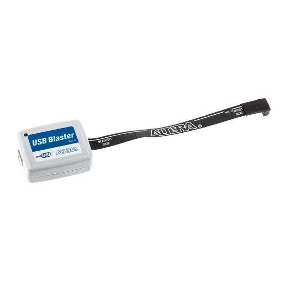
1. Setting Up the USB-Blaster Download Cable Introduction The USB-Blaster™ download cable interfaces a USB port on a host computer to an ® Altera FPGA mounted on a printed circuit board. The cable sends configuration data from the PC to a standard 10-pin header connected to the FPGA. You can use the USB-Blaster cable to iteratively download configuration data to a system during prototyping or to program data into the system during production. -
Page 10: Software Requirements
1. Disconnect the power cable from the circuit board. 2. Connect the USB cable to the USB port on your PC and to the USB-Blaster port. 3. Connect the USB-Blaster download cable to the 10-pin header on the device board. -
Page 11: Software Setup
1–3 Software Setup To avoid damaging the USB-Blaster cable, first unplug the cable from the 10-pin header on the target board before unplugging the cable from the USB port on your PC. It is safest to remove power first from the target board before unplugging the USB-Blaster cable. -
Page 12: Installing The Usb-Blaster Driver On Windows 2000 And Windows Xp Systems
Before you begin the installation, verify that the USB-Blaster driver is located in your directory: \<Quartus II system directory>\drivers\usb-blaster If the driver is not in your directory, download the USB-Blaster driver from the Altera web site: www.altera.com/support/software/drivers To install the driver, follow the directions below: 1. -
Page 13: Installing The Usb-Blaster Driver On Linux
The Quartus II software uses the built-in USB drivers (usbfs) on RedHat Linux to access the USB-Blaster download cable. By default, root is the only user allowed to use usbfs. You must change the permission on the ports before you can use the USB-Blaster download cable to program devices with the Quartus II software. -
Page 14: Setting Up The Usb-Blaster Hardware In The Quartus Ii Software
Software Setup For Red Hat Enterprise 5 1. Create a file named /etc/udev/rules.d/51-usbblaster.rules and add the following lines to it. Take note that after #USB-Blaster, all code must be in one line. # USB-Blaster BUS=="usb", SYSFS{idVendor}=="09fb", SYSFS{idProduct}=="6001", MODE="0666", PROGRAM="/bin/sh -c 'K=%k; K=$${K#usbdev}; printf /proc/bus/usb/%%03i/%%03i $${K%%%%.*} $${K#*.}'", RUN+="/bin/chmod 0666... -
Page 15: Table 1-1: Programming Modes
Software Setup Table 1–1. Programming Modes Mode Mode Description Joint Test Action Programs or configures all Altera devices supported by Quartus II Group (JTAG) software, excluding FLEX 6000 and EPCS serial configuration devices. In-Socket Not supported by the USB-Blaster. Programming... - Page 16 1–8 Chapter 1: Setting Up the USB-Blaster Download Cable Software Setup USB-Blaster Download Cable User Guide © April 2009 Altera Corporation...
-
Page 17: Overview
“Statement of China-RoHS Compliance” on page 2–8 USB-Blaster Connections The USB-Blaster cable has a USB universal plug that connects to the PC USB port, and a 10-pin female plug that connects to the circuit board. Data is downloaded from the USB port on the PC through the USB-Blaster cable to the circuit board via the connections discussed in this section. -
Page 18: Cable-To-Board Connection
2–2 Chapter 2: USB-Blaster Specifications USB-Blaster Connections Table 2–1. USB-Blaster VCC(TRGT) Pin Voltage Requirements (Part 2 of 2) Device Family USB-Blaster VCC Voltage Required Cyclone II, Cyclone, As specified by V CCIO APEX II, APEX 20K, and Mercury devices FLEX 10K, FLEX 8000,... -
Page 19: Usb-Blaster Plug Connection
The 10-pin female plug connects to a 10-pin male header on the circuit board containing the target device. Figure 2–2 shows the dimensions of the USB-Blaster, and Figure 2–3 shows the dimension of the female plug. Figure 2–2. USB-Blaster Dimension Dimensions are shown in inches. -
Page 20: Circuit Board Header Connection
I/O drivers. Circuit Board Header Connection The circuit board's 10-pin male header, which connects to the USB-Blaster cable's 10-pin female plug, has two rows of five pins. These pins are connected to the device’s programming or configuration pins. -
Page 21: Operating Conditions
— 1.43 1.57 1.5-V operation Note to Table 2–4: (1) This operating condition can be applicable to USB-Blaster Cable (Rev. A & B) Table 2–5. USB-Blaster Cable (Rev. A & B) DC Operating Conditions Symbol Parameter Conditions Unit High-level input —... -
Page 22: Table 2-6: Usb-Blaster Cable (Rev. C) Dc Operating Conditions
2–6 Chapter 2: USB-Blaster Specifications Operating Conditions Table 2–5. USB-Blaster Cable (Rev. A & B) DC Operating Conditions Symbol Parameter Conditions Unit 5.0-V high-level = 4.5 V, I = 1 mA CC(TRGT) output voltage 3.3-V high-level = 3.0 V, I... -
Page 23: Usb-Revision
Chapter 2: USB-Blaster Specifications 2–7 USB-Revision Table 2–6. USB-Blaster Cable (Rev. C) DC Operating Conditions Symbol Parameter Conditions Unit 5.0-V low-level output = 5.5 V, I = 10 mA CC(TRGT) voltage 3.3-V low-level output = 3.6 V, I = 8 mA... -
Page 24: Statement Of China-Rohs Compliance
2–8 Chapter 2: USB-Blaster Specifications Statement of China-RoHS Compliance Statement of China-RoHS Compliance Table 2–8 lists hazardous substances included with the USB-Blaster download cable (Rev. C). Table 2–8. Table of Hazardous Substances’ Name and Concentration (Note 1) Hexavalent Polybrominated Lead... - Page 25 ■ ■ Refer to the following introduction and overview topics in the Quartus II Help: Programmer Introduction ■ Overview: Working with Chain Description Files ■ Overview: Converting Programming Files ■ © April 2009 Altera Corporation USB-Blaster Download Cable User Guide...
- Page 26 2–10 Chapter 2: USB-Blaster Specifications References USB-Blaster Download Cable User Guide © April 2009 Altera Corporation...
-
Page 27: Additional Information
Added feetpara note on driver information just before the “Setting Up the USB-Blaster ■ Hardware in the Quartus II Software” section Updated USB-Blaster installation procedure for QII 6.1 (32-bit or 64-bit) in “Installing the ■ USB-Blaster Driver on Windows 2000 and Windows XP Systems” section... -
Page 28: How To Contact Altera
(Software Licensing) Email authorization@altera.com Note: (1) You can also contact your local Altera sales office or sales representative. Typographic Conventions The following table shows the typographic conventions that this document uses. Visual Cue Meaning Bold Type with Initial Capital Let-... - Page 29 A warning calls attention to a condition or possible situation that can cause injury to the user. The angled arrow indicates you should press the Enter key. The feet direct you to more information on a particular topic. © April 2009 Altera Corporation USB-Blaster Download Cable User Guide...
- Page 30 Mouser Electronics Authorized Distributor Click to View Pricing, Inventory, Delivery & Lifecycle Information: Terasic P0302...
Need help?
Do you have a question about the USB-Blaster and is the answer not in the manual?
Questions and answers