Table of Contents
Advertisement
Service
Manual
GB
Service Manual
Radiant Hob Manual
1 ISSUE MAR. 2008
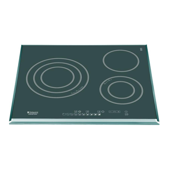
RADIANT HOBS
PLATFORM 2008
Model.
Covered
KRO 632 TD X
KRO 632 TD Z
KRO 642 D B
KRO 642 D X
KRO 642 D Z
KRO 642 TO B
KRO 642 TO X
KRO 642 TO Z
KRO 742 DO Z
KRO 742 TO Z
Edition
2008.03.01
Comm.
Code
52968
52969
52972
52973
52974
52975
52976
52977
52980
52981
Language
English
Advertisement
Table of Contents

Related Manuals for Hotpoint Ariston KRO 632 TD X


Summary of Contents for Hotpoint Ariston KRO 632 TD X
- Page 1 1 ISSUE MAR. 2008 RADIANT HOBS PLATFORM 2008 Model. Comm. Covered Code KRO 632 TD X 52968 KRO 632 TD Z 52969 KRO 642 D B 52972 KRO 642 D X 52973 KRO 642 D Z 52974 KRO 642 TO B...
-
Page 2: Table Of Contents
CONTENTS Chapter 01: Specifi cations Product label Legend Chapter 02: Control Panel Classic control panel Confort control panel Premium control pane Installing and fi tting the appliance Operative features Chapter 03: Components Wiring diagram Chapter 04: Technical Assistance 9-12 Demo Mode Autotest procedure Fault Table 10-12... -
Page 3: Service Manual
CHAPTER 1: SPECIFICATIONS 1.1: PRODUCT LABEL: Industrial code: 44 38942 0100 Aesthetic and functional modifi cations Commercial code MADE IN EU Factory code 44389420100 ......Mod. Cod. Serial 7200W 230/400 V 3N- 50Hz Number: S/N 606151306 6 06 15 1306 Correlative Month PIANO TIL 642... -
Page 4: Control Panel
CHAPTER 2: CONTROL PANEL 2.1: CLASSIC CONTROL PANEL: Function buttons 1 POWER and RESIDUAL HEAT indicator displays 10 CONTROL LOCK button prevents fortuitous mo- the level of heat reached. difi cations in hob adjustment. 2 COOKING ZONE indicator light indicates that the 11 PROGRAMMING TIMER* button adjusts the corresponding cooking zone has been selected programming of the cooking duration. -
Page 5: Confort Control Panel
2.2: CONFORT CONTROL PANEL: edium edium edium edium edium edium edium edium edium edium edium edium ooster o o ost oster er ooster o o ost oster er ooster o o ost oster er ooster o o ost oster er Function buttons 1 POWER and RESIDUAL HEAT indicator displays 10 CONTROL LOCK button prevents fortuitous mo-... -
Page 6: Premium Control Pane
2.3: PREMIUM CONTROL PANEL: Power Power Power Power Function buttons 1 COOKING ZONE indicator light indicates that the 10 ON/OFF button turns on/off the appliance. corresponding cooking zone has been selected 11 ON/OFF indicator light indicates if the appliance by the user, so it is possible to adjust it. is on/off. -
Page 7: Operative Features
2.4: INSTALLING AND FIXING THE APPLIANCE For all the instructions about product fi tting, ventilation, product fi xing to the cabinet, electrical connection, etc., refer to the handbook you can fi nd inside of the product package. 2.5: OPERATIVE FEATURES 2.5.1: Operative voltage: Voltage values assuring the correct operation of the appliance are the following ones listed below: 230 Volts, with a range of +/-10 % and 50 Hz. -
Page 8: Wiring Diagram
Sensor Display Board NTC: It is located on the Visual Board, the one between the two other boards which the Display Board consists of. The main function is to check the temperature on the zone where controls are located, stopping the appliance operation if it rises (when temperature reaches 105 °C) Residual Heat Indicator In Radiant Hobs, the residual heat indicator light is not controlled by sensors like NTC or PTC, but by sof-... -
Page 9: Technical Assistance
CHAPTER 4: TECHNICAL ASSISTANCE 4.1: DEMO MODE: Getting ready to use Demo Mode: 1. the hob is on 2. all the inductors are off To select DEMO function, press and hold for 6 seconds TIMER “+” and “-” buttons simultaneously; then POWER ON and BUTTON LOCK LED will fl... -
Page 10: Fault Table
4.3: FAULT TABLE: FAULT SUBCODE DESCRIPTION CHECK ACTIONS Visual board NTC SC • Replace the Display board Visual board NTC OC • Replace the Display board Comunication VISUAL <--> cookeye/ Fault Not available • clipsoeye MODULE 1. Check the correct installation of the Touch-Visual communication Flat 2. - Page 11 FAULT SUBCODE DESCRIPTION CHECK ACTIONS 1. Check the inductor, verifying that the contacts are well connected and clean. ISI UART 1 (CN 03): small induction 2. Check NTC ohmic values (it must not be SC or OC) hotplate not connected 3.
- Page 12 FAULT SUBCODE DESCRIPTION CHECK ACTIONS ISI UART 1 (CN 03): Too high tempe- 3. Verify that heat-sink NTC is calibrated. 4. Replace the corresponding generator board. rature of the heat-sink 1. Verify that the fan is correctly wired and that the wiring is intact. ISI UART 2 (CN 04): Too high tempe- 2.
-
Page 13: Chapter 05: Disassembly
CHAPTER 5: DISASSEMBLY Cooktop disassembly: 1. Remove the screws on the sides of the hob which fasten the base to the glass-ceramic cooktop. 2. Lift the glass-ceramic cooktop. Display Board disassembly: 1 Remove the cooktop. 2 Lift the Display Board 3 Detach all the connectors of the lower part of the board. - Page 14 Service Manual Edition Lingua Manuale Piani Radianti 2008.03.01 English...
Need help?
Do you have a question about the KRO 632 TD X and is the answer not in the manual?
Questions and answers