
Related Manuals for REXROTH A4VG


Summary of Contents for REXROTH A4VG
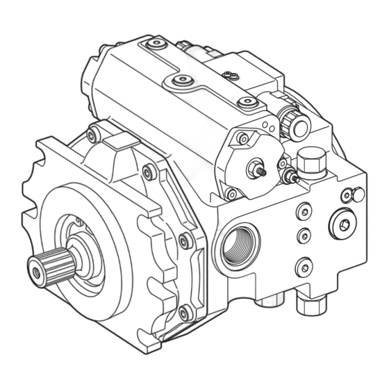
- Page 1 Axial Piston Variable Pump RE 92004-01-S031/08.2015 Replaces: 09.2011 A4VG English Series 40 Repair Manual...
- Page 2 © This document, as well as the data, specifications and other information set forth in it, are the exclusive property of Bosch Rexroth AG. It may not be reproduced or given to third parties without its consent.
-
Page 3: Table Of Contents
RE 92004-01-S031/08.2015 | A4VG Series 40 Bosch Rexroth AG 3/40 Contents Inhalt 1 About this manual ..................4 Related documents ...................4 Abbreviations used ...................5 2 General safety instructions ................6 Intended use .....................6 Improper use .....................6 Personnel qualifications ................6 Safety instructions in this manual .............7 Adhere to the following instructions ............7... -
Page 4: About This Manual
A4VG. 1.1 Related documents The axial piston variable pump A4VG is a system component. Also observe the manuals for the other system components. Further information on the axial piston variable pump A4VG and its installation, commissioning and operation can be found in the Rexroth documents listed in the following table. -
Page 5: Abbreviations Used
RE 92004-01-S031/08.2015 | A4VG Series 40 Bosch Rexroth AG 5/40 About this manual 1.2 Abbreviations used As umbrella term for "axial piston variable pump A4VG", the designation "axial piston unit" will be used in the following. Table 2: Abbreviations Abbreviation Meaning... -
Page 6: General Safety Instructions
2.2 Improper use Any use other than that described as intended use shall be considered as improper and is therefore impermissible. Bosch Rexroth AG shall accept no liability whatsoever for damage resulting from improper use. The user shall bear all risks arising from improper use. -
Page 7: Safety Instructions In This Manual
• Observe the regulations for accident prevention and environmental protection for the country where the product is used and at the workplace. • Only operate Rexroth axial piston units in good technical order and condition. • Use the product only within the performance range provided in the technical data. - Page 8 • Special tools are required for the repair. Repair without the required special tools is not permissible. • Use only original spare parts from Rexroth for the repair. • Replace the seals with new ones during the repair operation. • All components must be clean and undamaged.
-
Page 9: Operator's Obligations
9/40 General safety instructions 2.6 operator's obligations The operator of the Rexroth axial piston unit must provide personnel training on a regular basis regarding the following subjects: • Observation and use of the instruction manual and the legal regulations • Intended use and operation of the axial piston unit •... -
Page 10: Product Description
10/40 Bosch Rexroth AG A4VG Series 40 | RE 92004-01-S031/08.2015 Product description 3 Product description This chapter provides a general overview of the functionality of the variable pump. Familiarize yourself with the contents of this chapter before you begin working on a variable pump. -
Page 11: Functional Description
A detailed functional description is contained in the product-specific instruction manual RE 92004-01-B. The following sectional drawing shows the design of the A4VG series 40 axial piston pump schematically. Fig. 2: Sectional drawing of variable pump... -
Page 12: Technical Data
A4VG Series 40 | RE 92004-01-S031/08.2015 Product description 3.3 Technical data The technical data of the variable pump can be found in the order confirmation. These are supplemented by the technical data sheet. Technical data sheet RE 92004 applies to the A4VG variable pump. -
Page 13: Controller
RE 92004-01-S031/08.2015 | A4VG Series 40 Bosch Rexroth AG 13/40 Controller 4 Controller The material numbers for the special tools are to be found in the Special Tool Catalog RE 92004-01-S081. If not explicitly specified, permissible tightening torques for the bolted connections are to be found in Chapter "10 Settings". -
Page 14: Sealing Controller
14/40 Bosch Rexroth AG A4VG Series 40 | RE 92004-01-S031/08.2015 Controller 4.2 Sealing controller This section describes how you seal the controller. There is a wide variety of controllers. Please note that the sealing of only one such controller is shown here exemplarily. -
Page 15: Installing The Controller
RE 92004-01-S031/08.2015 | A4VG Series 40 Bosch Rexroth AG 15/40 Controller 4.3 Installing the controller This section describes how you install the controller. There is a wide variety of controllers. Please note that the installation of only one such controller is shown here exemplarily. -
Page 16: Setting Controller (Hydraulic Neutral Position)
16/40 Bosch Rexroth AG A4VG Series 40 | RE 92004-01-S031/08.2015 Controller 4.4 Setting controller (hydraulic neutral position) This section describes how you set the hydraulic neutral position. There is a wide variety of controllers. Please note that the configuration of only one such controller is shown here exemplarily. -
Page 17: Internal Gear Pump
RE 92004-01-S031/08.2015 | A4VG Series 40 Bosch Rexroth AG 17/40 Internal gear pump 5 Internal gear pump The material numbers for the special tools are to be found in the Special Tool Catalog RE 92004-01-S081. If not explicitly specified, permissible tightening torques for the bolted connections are to be found in Chapter "10 Settings". -
Page 18: Seal/Install Internal Gear Pump Cover
18/40 Bosch Rexroth AG A4VG Series 40 | RE 92004-01-S031/08.2015 Internal gear pump 5.2 Seal/install internal gear pump cover This section describes how you seal/install the internal gear pump cover. Fig. 8: Internal gear pump cover 1 Fixing screws 5 O-ring... -
Page 19: Shaft Seal
RE 92004-01-S031/08.2015 | A4VG Series 40 Bosch Rexroth AG 19/40 Shaft seal 6 Shaft seal The material numbers for the special tools are to be found in the Special Tool Catalog RE 92004-01-S081. If not explicitly specified, permissible tightening torques for the bolted connections are to be found in Chapter "10 Settings". -
Page 20: Valves
20/40 Bosch Rexroth AG A4VG Series 40 | RE 92004-01-S031/08.2015 Valves 7 Valves The material numbers for the special tools are to be found in the Special Tool Catalog RE 92004-01-S081. If not explicitly specified, permissible tightening torques for the bolted connections are to be found in Chapter "10 Settings". - Page 21 RE 92004-01-S031/08.2015 | A4VG Series 40 Bosch Rexroth AG 21/40 Valves Procedure To replace the valve seal and the valve insert: Loosen the high pressure relief valve (6) and screw the high pressure relief valve (6) out of the pump case (7).
-
Page 22: Seal/Replace Low Pressure Relief Valve
22/40 Bosch Rexroth AG A4VG Series 40 | RE 92004-01-S031/08.2015 Valves Tighten the high pressure relief valve with the tightening torque necessary for the corresponding model: Table 3: Tightening torques Required tightening Size torque up to 110 250 Nm above 145 375 Nm Check high pressure - see Chapter "10 Settings". - Page 23 RE 92004-01-S031/08.2015 | A4VG Series 40 Bosch Rexroth AG 23/40 Valves Procedure To replace the valve seal: Loosen the low pressure relief valve (6) and screw the low pressure relief valve (6) out of the pump case (7). Check the O-ring and O-ring groove for damage, wear or contaminants.
-
Page 24: Seal/Replace Pressure Cut-Off
24/40 Bosch Rexroth AG A4VG Series 40 | RE 92004-01-S031/08.2015 Valves 7.3 Seal/replace pressure cut-off The section describes how you seal/replace the pressure cut-off. Fig. 13: Pressure cut-off 1 Pump case 7 Pressure spring 2 O-ring 8 Threaded plug 3 Pressure cut-off... -
Page 25: Set Pressure Cut-Off
RE 92004-01-S031/08.2015 | A4VG Series 40 Bosch Rexroth AG 25/40 Valves 7.3.1 Set pressure cut-off This section describes how you check the pressure cut-off. Risk of injury! WARnInG! The following works on the variable pump are dangerous. Pay close attention to the safety instructions (see Chapter "2 General safety instructions"). -
Page 26: Seal Control Cartridge
26/40 Bosch Rexroth AG A4VG Series 40 | RE 92004-01-S031/08.2015 Valves 7.4 Seal control cartridge This section describes how you seal the control cartridge. Fig. 15: Control cartridge 1 Control cartridge 3 Pump case 2 O-ring Procedure To replace the valve seal: When replacing the SEAL LOCK sealing nut on the adjusting screw for the beginning of control, re-insert the yellow protective cap. -
Page 27: Set Beginning Of Control
RE 92004-01-S031/08.2015 | A4VG Series 40 Bosch Rexroth AG 27/40 Valves 7.4.1 Set beginning of control The exact settings are to be found in the data sheet in your order documentation or in your specification. Procedure To set the beginning of control: Warm up the drive (Oil temperature 50 - 60 °C). -
Page 28: Seal Shuttle Valve
28/40 Bosch Rexroth AG A4VG Series 40 | RE 92004-01-S031/08.2015 Valves 7.5 Seal shuttle valve This section describes how you seal the shuttle valve. Fig. 16: Shuttle valve 1 Pump case 5 Stop screw 2 O-ring 6 Sleeve 3 O-ring... -
Page 29: Exchange Angle Position Sensor
RE 92004-01-S031/08.2015 | A4VG Series 40 Bosch Rexroth AG 29/40 Valves 7.6 Exchange angle position sensor This section explains how to replace the angle position sensor. Fig. 17: Angle position sensor 1 Fixing screws 3 Bearing flange 2 Angle position sensor... -
Page 30: Filter
30/40 Bosch Rexroth AG A4VG Series 40 | RE 92004-01-S031/08.2015 Filter 8 Filter The material numbers for the special tools are to be found in the Special Tool Catalog RE 92004-01-S081. If not explicitly specified, permissible tightening torques for the bolted connections are to be found in Chapter "10 Settings". -
Page 31: Seal/Replace Filter Head
RE 92004-01-S031/08.2015 | A4VG Series 40 Bosch Rexroth AG 31/40 Filter Screw the filter housing (4) onto the filter head (1). Tighten the filter housing (4) with 45 Nm. 8.2 Seal/replace filter head This section describes how you seal/replace the filter head. -
Page 32: Threaded Plugs
32/40 Bosch Rexroth AG A4VG Series 40 | RE 92004-01-S031/08.2015 Threaded plugs 9 Threaded plugs The material numbers for the special tools are to be found in the Special Tool Catalog RE 92004-01-S081. If not explicitly specified, permissible tightening torques for the bolted connections are to be found in Chapter "10 Settings". - Page 33 RE 92004-01-S031/08.2015 | A4VG Series 40 Bosch Rexroth AG 33/40 Threaded plugs Exchange the O-Ring (2) for a new one. Screw the threaded plug (1) into the pump case (3). Tighten the threaded plug with the necessary tightening torque. For the tightening torques for threaded plugs, see Chapter "10 Settings".
-
Page 34: Settings
Installation settings: • Tightening torques Make all settings with the equipment at operating temperature (Oil temperature 50 - 60 °C). If the values checked deviate from the original settings, contact Bosch Rexroth Service regarding the setting. Risk of injury! WARnInG! Working on the variable pump at operating temperature is dangerous. -
Page 35: Low Pressure
RE 92004-01-S031/08.2015 | A4VG Series 40 Bosch Rexroth AG 35/40 Settings 10.1 low pressure This section describes how you check low pressure. Risk of injury! WARnInG! The following works on the variable pump are dangerous. Pay close attention to the safety instructions (see Chapter "2 General safety instructions"). -
Page 36: High Pressure
36/40 Bosch Rexroth AG A4VG Series 40 | RE 92004-01-S031/08.2015 Settings 10.2 High pressure This section describes how you check high pressure. Risk of injury! WARnInG! The following works on the variable pump are dangerous. Pay close attention to the safety instructions (See Chapter "2 General safety instructions"). -
Page 37: Tightening Torques
RE 92004-01-S031/08.2015 | A4VG Series 40 Bosch Rexroth AG 37/40 Settings 10.3 Tightening torques The following tightening torques apply: • Fittings: Observe the manufacturer's instructions regarding the tightening torques of the fittings used. • Internal threads of the axial piston unit:... - Page 38 38/40 Bosch Rexroth AG A4VG Series 40 | RE 92004-01-S031/08.2015 Settings Table 6: Tightening torques for the fixing screws Thread Tightening torque Strength classes 10.9 12.9 1.1 Nm 1.6 Nm 1.9 Nm 2.6 Nm 3.9 Nm 4.5 Nm 5.2 Nm 7.6 Nm...
- Page 39 RE 92004-01-S031/08.2015 | A4VG Series 40 Bosch Rexroth AG 39/40...
-
Page 40: Re 92004-01-S031/08.2015 | A4Vg Series 40 Bosch Rexroth Ag
Bosch Rexroth AG Axial piston units Glockeraustrasse 4 89275 Elchingen, Germany Tel. +49-7308-82-0 Fax +49-7308-72-74 info.brm-ak@boschrexroth.de www.boschrexroth.com/brm Printed in Germany RE 92004-01-S031/08.2015...
Need help?
Do you have a question about the A4VG and is the answer not in the manual?
Questions and answers