
Related Manuals for Garmin GMA 1347D-00


Summary of Contents for Garmin GMA 1347D-00
- Page 1 GMA 1347D Installation Manual (GMA 1347D -00 Shown) 190-00303-21 January, 2010 Revision C...
- Page 2 Garmin. Garmin hereby grants permission to download a single copy of this manual and of any revision to this manual onto a hard drive or other electronic storage medium to be viewed and...
- Page 3 CURRENT REVISION DESCRIPTION Page Section Revision Description of Change Number(s) Number Added “DME, ADF, MKR, TEL, AUX” to Equipment Description 1.2.2 Added to Interface Summary Updated warranty statement & Updated AC reference 2.2.2 Added marker beacon installation guidance 2-2 – 2-3 2.3.1 DOCUMENT PAGINATION Section...
- Page 4 California to cause cancer, birth defects, or reproductive harm. This notice is being provided in accordance with California’s proposition 65. If you have any questions or would like additional information, please refer site www.garmin.com/prop65. Page GMA 1347D Installation Manual Revision C 190-00303-21...
-
Page 5: Table Of Contents
TABLE OF CONTENTS PARAGRAPH PAGE GENERAL DESCRIPTION......................1-1 1.1 Introduction............................1-1 1.2 Equipment Description ........................1-1 1.3 Technical Specifications ........................1-3 1.4 Certification ............................1-5 1.5 Reference Documents ........................1-6 1.6 Limited Warranty..........................1-7 INSTALLATION OVERVIEW ......................2-1 2.1 Introduction............................2-1 2.2 Installation Materials .........................2-1 2.3 Installation Considerations ........................2-2 2.4 Cabling &... - Page 6 PARAGRAPH PAGE APPENDIX A ASSEMBLY AND INSTALLATION DRAWINGS............A-1 APPENDIX B INTERCONNECT DRAWINGS ..................B-1 LIST OF ILLUSTRATIONS FIGURE PAGE 2-1 GMA Marker Beacon Coaxial Cable D-Sub Termination..............2-3 2-2 GMA 1347D Unit Rack........................2-5 4-1 Rear Connectors, J3471 and J3472 Viewed From Back of Unit ............4-1 A-1 GMA 1347D Outline Drawing ......................
- Page 7 LIST OF TABLES TABLE PAGE 2-1 Pin and Crimp Tool Part Numbers.....................2-3 3-1 Pin Contact Part Numbers........................3-1 3-2 Recommended Crimp Tools ......................3-2 4-1 J3471 Pin Assignments........................4-2 4-2 J3472 Pin Assignments........................4-4 4-3 Aircraft Power Pin Assignments, J3472 ....................4-6 4-4 Aircraft Lighting Pin Assignments, J3472..................4-6 4-5 RS-232 Pin Assignments, J3472......................4-6 4-6 Marker Beacon Pin Assignments, J3472 ...................4-7 4-7 Reversionary Mode Pin Assignments, J3472 ..................4-8...
- Page 8 The table is current at the time of publication of this manual (see date on front cover) and is subject to change without notice. Authorized Garmin Sales and Service Centers are encouraged to access the most up-to-date bulletin and advisory information on the Garmin Dealer Resource web site at www.garmin.com using their Garmin-provided user name and password.
-
Page 9: General Description
This manual presents mechanical and electrical installation requirements for installing the Garmin GMA 1347D audio panel, as part of the Garmin Integrated Flight Deck. The GMA 1347D can be incorporated into a variety of airframes under appropriate TC or STC. Each airframe installation may vary. - Page 10 1.2.1 Features Summary • Logical front panel layout • LED annunciators indicate selected function • Five position intercom: pilot and four passengers • Two stereo headset amplifiers: one for the pilot and one for the passengers • Two stereo music source inputs •...
-
Page 11: Technical Specifications
Environmental Qualification Form. This form is available directly from Garmin under the following part number: GMA 1347D Environmental Qualification Form, Garmin part number 005-00314-79 To obtain a copy of this form, see the dealer/OEM portion of the Garmin web site (www.garmin.com). 1.3.1 Physical Characteristics Characteristic... - Page 12 1.3.2 Electrical Characteristics Characteristic Specification Regulatory Compliance RTCA/DO-160D Environmental Conditions and EUROCAE/ED-14D Unit Software RTCA/DO-178B Level C CLD (Custom Logic RTCA/DO-254 Level C Devices) Compliance Temperature Range -45°C to +70°C Supply Voltage: 28 VDC Power Requirements See the Environmental Qualification Form for details on surge ratings and minimum/maximum operating voltages.
-
Page 13: Certification
RTCA DO-138 as the standard for Environmental Conditions and Test Procedures for Airborne Equipment. 2. Garmin was granted a deviation from TSO-C35d to use FAR §21.607(d) instead of FAR §37.7 as the general rules governing holders of the TSO authorizations. -
Page 14: Reference Documents
Reference Documents The following publications are sources of additional information for installing the GMA 1347D. Before installing the unit, the technician should read all referenced materials along with this manual. Part Number Document 190-00303-00 G1000 System Installation Manual G1000 Line Maintenance and 190-00303-04 Configuration Manual Page 1-6... -
Page 15: Limited Warranty
(iv) damage caused by service performed by anyone who is not an authorized service provider of Garmin; or (v) damage to a product that has been modified or altered without the written permission of Garmin. - Page 16 This page intentionally left blank Page 1-8 GMA 1347D Installation Manual Revision C 190-00303-21...
-
Page 17: Installation Overview
The guidance of FAA advisory circulars AC 43.13-1B and AC 43.13-2B, where applicable, may be found useful for making retro-fit installations that comply with FAA regulations. Refer to the G1000 System Installation Manual, Garmin part number 190-00303-00 for further details on the mechanical aspects of the G1000 system. -
Page 18: Installation Considerations
Installation Considerations The GMA 1347D interfaces with the G1000 system, and with various avionics equipment. Fabrication of a wiring harness is required. Sound mechanical and electrical methods and practices are required for installation of the GMA 1347D. 2.3.1 Marker Beacon Antenna Installation 2.3.1.1 Location Considerations The marker beacon antenna should be mounted on a flat surface on the underside of the aircraft body. -
Page 19: Pin And Crimp Tool Part Numbers
Tool, Pin, and Crimp Tool Insert part numbers. Figure 2-1. GMA Marker Beacon Coaxial Cable D-Sub Termination Table 2-1. Pin and Crimp Tool Part Numbers CRIMP TOOL CRIMP TOOL INSERT Garmin Part Number DANIELS MANUFACTURING CORP 336-00021-00 DMC M22520/2-01 GAGE Garmin Part Number... -
Page 20: Cabling & Wiring
Use AWG #24 or larger wire for all connections unless otherwise specified by the aircraft manufacturer or Garmin. The standard pin contacts supplied in the connector kit are compatible with up to AWG #22 wire. In cases where some installations have more than one unit sharing a common circuit breaker, sizing and wire gauge is based on aircraft circuit breaker layout, length of wiring, current draw of units, and internal unit protection characteristics. -
Page 21: Mounting Requirements
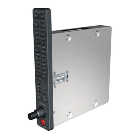
Mounting Requirements The GMA 1347D mounting surface must be capable of providing structural support and electrical bond to the aircraft to minimize radiated EMI and provide protection from High-Intensity Radiation Fields (HIRF). The GMA 1347D is mounted using its own system rack. Figure 2-2 shows the GMA 1347D unit rack. The unit rack is fastened to the aircraft instrument panel using the nutplate kit and bracket kit listed in Section 2.2.1. -
Page 22: Installation Approval Considerations For Pressurized Aircraft
Installation Approval Considerations for Pressurized Aircraft Antenna and cable installations on pressurized cabin aircraft require FAA approved installation design and engineering substantiation data whenever such installations incorporate alteration (penetration) of the cabin pressure vessel by connector holes and/or mounting arrangements. For needed engineering support pertaining to the design and approval of such pressurized aircraft antenna installations, it is recommended that the installer proceed according to any of the following listed alternatives:... -
Page 23: Installation Procedure
If the unit is damaged, notify the carrier and file a claim. To justify a claim, save the original shipping container and all packing materials. Do not return the unit to Garmin until the carrier has authorized the claim. -
Page 24: Backshell Assembly
615725 M81969/1-04 NOTES 1. Non-Garmin part numbers shown are not maintained by Garmin and consequently are subject to change without notice. 2. Extracting the #16, #18 and #20 contact requires that the expanded wire barrel be cut off from the contact. It may also be necessary to push the pin out from the face of the connector when using an extractor due to the absence of the wire. -
Page 25: Gma 1347D Unit Installation
The GMA 1347D does not provide valid outputs until the aircraft post installation configuration procedures are completed. The GMA 1347D must be installed with a Garmin G1000 system and have FAA approved configuration data. Configuration data is loaded to the GMA 1347D from an aircraft-specific G1000 SW Loader Card. -
Page 26: Section 3 3-1 –
This page intentionally left blank Page 3-4 GMA 1347D Installation Manual Revision C 190-00303-21... -
Page 27: System Interconnects
SYSTEM INTERCONNECTS Connector Description The GMA 1347D has two 78-pin connectors located at the rear of the unit designated J3471 and J3472. J3471 and J3472 are clearly marked on the back of the rack. J3471 and J3472 pins are configured as shown in the following illustration: 41 42 51 52... -
Page 28: J3471 Pin Assignments
Table 4-1. J3471 Pin Assignments Pin Name FAIL SAFE WARN AUDIO IN (-00) FAIL SAFE PILOT SUMMED AUDIO OUT HI (-20) OXYGEN MASK MIC SELECT* TEL RINGER AUDIO IN HI TEL RINGER AUDIO IN LO REMOTE PASS ICS OUT HI ON-SIDE NAV AUDIO IN HI ON-SIDE COM AUDIO IN HI ON-SIDE COM AUDIO LO... - Page 29 Table 4-1. J3471 Pin Assignments (Continued) Pin Name UNSWITCHED AUDIO IN 3 HI UNSWITCHED AUDIO IN LO REMOTE PASS ICS AUDIO IN HI REMOTE PASS ICS AUDIO IN LO TEL AUDIO IN HI TEL AUDIO IN LO PASS 3 MIC AUDIO IN HI PASS 3 MIC AUDIO IN LO PASS 1 MIC AUDIO IN HI PASS 1 MIC AUDIO IN LO...
-
Page 30: J3472 Pin Assignments
Table 4-2. J3472 Pin Assignments Pin Name RESERVED RESERVED PROGRAM GROUND RESERVED PROGRAM GROUND RS-232 OUT 1 RS-232 IN 1 ON-SIDE COM MIC DIGITAL AUDIO OUT ON-SIDE COM DIGITAL AUDIO IN RESERVED PROGRAM GROUND SPARE SPARE POWER GROUND RESERVED POWER GROUND COM SWAP* PROGRAM GROUND SPARE... - Page 31 Table 4-2. J3472 Pin Assignments (Continued) Pin Name RS-232 OUT 2 RS-232 IN 2 RESERVED SPEAKER AUDIO OUT LO SPEAKER AUDIO OUT HI RESERVED PROGRAM GROUND RESERVED PROGRAM GROUND CROSS-SIDE COM MIC DIGITAL AUDIO OUT CROSS-SIDE COM DIGITAL AUDIO IN SECONDARY DIGITAL AUDIO CLOCK OUT SECONDARY DIGITAL AUDIO CLOCK IN 14 V LIGHTING HI...
-
Page 32: J3472 Connector Pin Assignments
J3472 Connector Pin Assignments This section covers the pin connections of J3472 only. 4.3.1 Aircraft Power and Lighting Power Input requirements and Lighting Bus inputs are listed in the following tables. The power-input pins accept 11-33 Vdc. AIRCRAFT POWER 2 is for connecting to an alternate power source, such as on aircraft with two electrical buses. -
Page 33: Marker Beacon Pin Assignments, J3472
4.3.3 RS-232 Serial Input/Output Table 4-5. RS-232 Pin Assignments, J3472 Pin Name Description RS-232 OUT 1 Output level greater than ±5 Volts RS-232 IN 1 Input level up to ±25 volts RS-232 OUT 2 Output level greater than ±5 Volts RS-232 IN 2 Input with level up to ±25 volts The RS-232 outputs conform to EIA/TIA-232C with an output voltage swing of at least ±5 V when... -
Page 34: Speaker Pin Assignments, J3472
4.3.6 Speaker The speaker output is capable of driving up to 10 Watts into a 4 Ω or 8 Ω speaker. Table 4-8. Speaker Pin Assignments, J3472 Pin Name Description SPEAKER AUDIO OUT LO Ground reference for speaker audio SPEAKER AUDIO OUT HI Speaker audio output 4.3.7 Digital Audio... -
Page 35: J3471 Connector Pin Assignments
J3471 Connector Pin Assignments This section covers the pin connections of J3471 only. 4.4.1 Mic Audio Inputs and Mic Keys Table 4-11. Mic Audio Inputs and Mic Key Pin Assignments, J3471 Pin Name Description Enables audio into the respective PILOT MIC KEY* IN transceiver unit PILOT MIC AUDIO IN HI Pilot Mic audio input and ground reference... -
Page 36: Com Audio And Mic Keys Pin Assignments, J3471
4.4.3 Com Audio and Mic Keys Table 4-13. Com Audio and Mic Keys Pin Assignments, J3471 Pin Name Description ON-SIDE COM MIC KEY* Enables audio into the respective CROSS-SIDE COM MIC KEY* transceiver unit COM 3 MIC KEY* COM 1 audio input for GMA #1 ON-SIDE COM AUDIO IN HI COM 2 audio input for GMA #2 COM 1 audio output for GMA #1... -
Page 37: Headset Outputs Pin Assignments, J3471
4.4.5 Headset Outputs Table 4-15. Headset Outputs Pin Assignments, J3471 Pin Name Description PILOT HEADSET AUDIO OUT LEFT Pilot headset audio output PILOT HEADSET AUDIO OUT RIGHT PILOT HEADSET AUDIO OUT LO Ground reference for pilot headset PASS HEADSET AUDIO OUT LEFT Passenger headset audio output PASS HEADSET AUDIO OUT RIGHT Ground reference for passenger... -
Page 38: Section 4 4-1 –
4.4.9 AUX, DME and ADF Audio Table 4-19. AUX, DME and ADF Audio Pin Assignments, J3471 Pin Name Description AUX AUDIO IN HI Extra switched audio input AUX AUDIO IN LO Ground reference for extra switched audio input DME AUDIO IN HI Distance measuring equipment audio input DME AUDIO IN LO Ground reference for DME audio input... -
Page 39: Appendix A Assembly And Installation Drawings
APPENDIX A ASSEMBLY AND INSTALLATION DRAWINGS Figure A-1. GMA 1347D Outline Drawing GMA 1347D Installation Manual Page A-1 (Page A-2 blank) 190-00303-21 Revision C... - Page 40 APPENDIX A ASSEMBLY AND INSTALLATION DRAWINGS Figure A-2. GMA 1347D Connector/Rack Assembly Drawing GMA 1347D Installation Manual Page A-3 (Page A-4 blank) 190-00303-21 Revision C...
- Page 41 APPENDIX A ASSEMBLY AND INSTALLATION DRAWINGS R.200 5.08 4.533 115.13 .130 3.30 100° .230 2X 3.398 86.30 R.063 1.59 MAX. 3.073 78.04 BEZEL CENTER .028 0.70 .450 11.43 .683 17.34 0 0.00 .300 7.62 CUTOUT CENTER NOTES: 1. DIMENSIONS: INCHES [mm] 2.
-
Page 42: Appendix B Interconnect Drawings
APPENDIX B INTERCONNECT DRAWINGS Figure B-1. GMA 1347D Power, Antenna and Reversionary Mode Interconnect Wiring Diagram GMA 1347D Installation Manual Page B-1 (Page B-2 blank) 190-00303-21 Revision C... - Page 43 APPENDIX B INTERCONNECT DRAWINGS Figure B-2. GMA 1347D Power, Antenna and Reversionary Mode Interconnect Wiring Diagram GMA 1347D Installation Manual Page B-3 (Page B-4 blank) 190-00303-21 Revision C...
- Page 44 APPENDIX B INTERCONNECT DRAWINGS Figure B-3. Mic and Phone Jack Connections, Interconnect Wiring Diagram GMA 1347D Installation Manual Page B-5 (Page B-6 blank) 190-00303-21 Revision C...
- Page 45 APPENDIX B INTERCONNECT DRAWINGS Figure B-4. Transceiver Analog Connections, Interconnect Wiring Diagram GMA 1347D Installation Manual Page B-7 (Page B-8 blank) 190-00303-21 Revision C...
- Page 46 APPENDIX B INTERCONNECT DRAWINGS Figure B-5. Transceiver Digital Connections, Interconnect Wiring Diagram GMA 1347D Installation Manual Page B-9 (Page B-10 blank) 190-00303-21 Revision C...
- Page 47 APPENDIX B INTERCONNECT DRAWINGS Figure B-6. Discrete Lines, Interconnect Wiring Diagram GMA 1347D Installation Manual Page B-11 (Page B-12 blank) 190-00303-21 Revision C...
Need help?
Do you have a question about the GMA 1347D-00 and is the answer not in the manual?
Questions and answers