Table of Contents
Advertisement
Advertisement
Table of Contents

Related Manuals for Invacare 3G Storm Series Torque ST


Summary of Contents for Invacare 3G Storm Series Torque ST
-
Page 1: User Manual
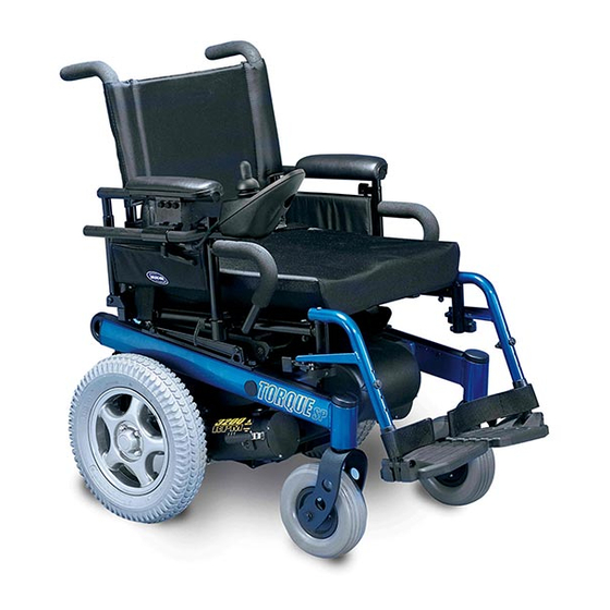
® Invacare 3G Storm Series Invacare 3G Storm Series Torque™ SP Invacare 3G Storm Series Torque 3 Power Wheelchair Base User Manual This manual MUST be given to the user of the product. BEFORE using this product, read this manual and save for future reference. - Page 2 © 2016 Invacare Corporation. All rights reserved. Republication, duplication or modification in whole or in part is prohibited without prior written permission from Invacare. Trademarks are identified by ™ and ®. Making Life's Experiences Possible is a registered trademark in the U.S.A. All trademarks are owned by or licensed to Invacare Corporation or its subsidiaries unless otherwise noted.
-
Page 3: Table Of Contents
Operation Guidelines............................................25 Transport Guidelines ............................................26 Safety/Handling ..............................................27 ELECTROMAGNETIC COMPATABILITY (EMC) INFORMATION Electromagnetic Interference (EMI) From Radio Wave Sources.............................. 44 Electromagnetic Interference (EMI)......................................... 45 Electromagnetic Emission........................................... 46 TECHNICAL DATA Specifications................................................. 47 Part No 1143151 Invacare 3G Storm Series®... - Page 4 Cleaning.................................................. 87 Service Inspection ..............................................88 Batteries ................................................. 90 Using the Proper Batteries ..........................................92 Recommended Battery Types........................................... 93 Replacing Batteries .............................................. 94 Removing/Installing Battery Boxes........................................95 Installing/Removing Batteries Into/From Battery Boxes ................................100 Invacare 3G Storm Series® Part No 1143151...
- Page 5 Adjusting the Extended Active Anti-Tippers....................................110 Disconnecting/Connecting the Joysticks ......................................112 10 TROUBLESHOOTING Driving Performance ............................................114 Electrical................................................114 Checking Battery Charge Level ........................................120 11 DISPOSAL Recycle..................................................121 12 WARRANTY Global Limited Warranty (Excluding Canada).....................................122 Canada Limited Warranty..........................................123 Part No 1143151 Invacare 3G Storm Series®...
-
Page 6: General
Caution indicates a potentially hazardous situation which, if not avoided, may result in property damage or minor injury or both. IMPORTANT Indicates a hazardous situation that could result in damage to property if it is not avoided. Gives useful tips, recommendations and information for efficient, trouble-free use. Invacare 3G Storm Series® Part No 1143151... -
Page 7: Reference Documents
Federal law restricts this device to sale by/on the order of a physician licensed by the law of the state in which he/she practices. Indications for Use The intended use of the Invacare 3G Storm Series Power Wheelchair is to provide mobility to persons limited to a sitting position, that have the ®... -
Page 8: Label Locations
Rear Battery Box Lid WARNING This wheelchair is to use ONLY Group 24 batteries, otherwise, injury to user and/or assistant or damage to the wheelchair may result. 1104924 C Front Battery Box Lid Invacare 3G Storm Series® Part No 1143151... - Page 9 4 Pole Motors with Group 24 Elevate Systems with Group 24 Batteries Only Batteries Only Auto style seat positioning strap shown. This label is also on the airline style seat positioning strap. Part No 1143151 Invacare 3G Storm Series®...
-
Page 10: Gearbox Assembly
Suspension Arm Used with Conventional Motor/ Gearbox Assembly WARNING When using a recliner/high back van seat, the motor/gearbox or motor MUST use most REARWARD mounting holes on the suspnsion arm assembly. P/N 1053056 Rev B Invacare 3G Storm Series® Part No 1143151... -
Page 11: Wheelchairs With O2 Holders
ASBA Seats WARNING Contact oxygen supplier for instructions in use of oxygen. Use EXTREME care when using oxygen near electric circuits. Remove oxygen cylinder when transporting wheelchair in a vehicle. 1080866 Rev C Part No 1143151 Invacare 3G Storm Series®... -
Page 12: Wheelchairs With Trro
2 LABEL LOCATIONS Wheelchairs with TRRO As of January 1, 2017. TRRO (Transport Ready Option) has been discontinued on this product. Please contact your dealer or Invacare for legacy information or to answer questions regarding TRRO. TIE DOWN POINT 1083199 D... -
Page 13: Wear And Tear Information
Invacare reserves the right to ask for any item back that has an alleged defect in workmanship. Refer to the Warranty section in this manual for specific warranty information. -
Page 14: Safety
Use of non-Invacare accessories may result in serious injury or damage. —Invacare products are specifically designed and manufactured for use in conjunction with Invacare accessories. Accessories designed by other manufacturers have not been tested by Invacare and are not recommended for use with Invacare products. - Page 15 Risk of Death, Serious Injury or Damage Use of incorrect or improper replacement (service) parts may cause death, serious injury, or damage. —Replacement parts MUST match original Invacare parts. —ALWAYS provide the wheelchair serial number to assist in ordering the correct replacement parts.
- Page 16 IMMEDIATELY. Invacare has tested its wheelchairs in accordance with RESNA WC— 2:2009, Section 9 Part 7.3 “Rain Test”. This provides the end user or his/her attendant sufficient time to remove his/her wheelchair from a rain storm and retain wheelchair operation.
- Page 17 —Ensure your wheelchair is working properly and is inspected by a qualified invacare technician if the wheelchair is involved in a collision or impact event.
- Page 18 —Monitor patients with these conditions frequently. —Close supervision and attention is needed when operating the wheelchair near children, pets or people with physical/ mental disabilities. Invacare 3G Storm Series® Part No 1143151...
- Page 19 —Turn power OFF BEFORE entering or exiting the wheelchair. —Close supervision and attention is needed when operating the wheelchair near children, pets or people with physical/ mental disabilities. —Turn power off when near children, pets or people with physical/mental disabilities Part No 1143151 Invacare 3G Storm Series®...
- Page 20 Risk of Death or Serious Injury Electric shock can cause death or serious injury. To avoid electric shock, inspect plug and cord for cuts and/or frayed wires. Replace cut cords or frayed wires immediately. Invacare 3G Storm Series® Part No 1143151...
- Page 21 When maneuvering the wheelchair around, ALWAYS have assured cleared distance with all objects in environment. Risk of Serious Injury Sharp edges can cause serious injury. Be mindful that some parts may have sharp edges. Use caution when encountering these sharp edges. Part No 1143151 Invacare 3G Storm Series®...
- Page 22 The mouthpiece/straw MUST be completely dry before installation. If Sip n’ Puff does not to function properly, inspect system for blockages, clogged saliva trap or air leaks. As necessary, replace mouthpiece, breath tube and saliva trap. Invacare 3G Storm Series® Part No 1143151...
-
Page 23: Setup Guidelines
THE INFORMATION CONTAINED IN THIS DOCUMENT IS SUBJECT TO CHANGE WITHOUT NOTICE. As a manufacturer of wheelchairs, Invacare endeavors to supply a wide variety of wheelchairs to meet many needs of the end user. However, final selection of the type of wheelchair to be used by an individual rests solely with the user and his/ her healthcare professional capable of making such a selection. - Page 24 —After the wheelchair has been set up/adjusted, check to make sure that the wheelchair performs to the specifications entered during the set up procedure. If the wheelchair does not perform to specifications, turn the wheelchair Off immediately and reenter set up specifications. Contact Invacare, if wheelchair still does not perform to correct specifications.
-
Page 25: Operation Guidelines
Risk of Serious Injury or Damage Improper transfer techniques may cause serious injury or damage. —Before attempting transfers, consult a health care professional to determine proper transfer techniques for the user and type of wheelchair. Part No 1143151 Invacare 3G Storm Series®... -
Page 26: Transport Guidelines
When using a stairway to move the wheelchair and any accessories, move all wheelchair components away from the stairway prior to reassembly. Invacare recommends using two assistants and making thorough preparations prior to transportation. Use an elevator or other accepted safe means of transportation between floors. -
Page 27: Safety/Handling
Use this information only as a “basic” guide. The techniques that are discussed on the following pages have been used successfully by many. Individual wheelchair users often develop skills to deal with daily living activities that may differ from those described in this manual. Invacare recognizes and encourages each individual to try what works best for him/her in overcoming architectural obstacles that they may encounter. - Page 28 —DO NOT drive in an elevated position while on an incline. —DO NOT leave elevating legrests in the fully extended position when proceeding down inclines/grades. —DO NOT leave an unoccupied wheelchair unattended on inclines or ramps. Invacare 3G Storm Series® Part No 1143151...
- Page 29 —If unintended/erratic movement occurs, stop using the wheelchair immediately and contact a qualified technician. —Ensure control knobs are secure before using the wheelchair. Stop using the wheelchair immediately and contact a qualified technician if control knobs are not secure. Part No 1143151 Invacare 3G Storm Series®...
- Page 30 Misuse of wheel locks may result in injury or damage. —DO NOT attempt to stop a moving wheelchair with the wheel locks. Wheel locks are not brakes. —DO NOT use the wheel locks (if equipped) when the wheelchair power is on. Invacare recommends the use of wheel locks.
- Page 31 Also, be aware of detachable parts such as arms or legrests. These must NEVER be used to move the wheelchair or as lifting supports, as they may be inadvertently released, resulting in possible injury to the user and/or assistant(s). When learning a new assistance technique, have an experienced assistant help you before attempting it alone. Part No 1143151 Invacare 3G Storm Series®...
- Page 32 —This wheelchair has been designed to accommodate one individual. DO NOT operate with additional person(s). —DO NOT carry heavy objects on your lap while operating the wheelchair. Invacare 3G Storm Series® Part No 1143151...
- Page 33 Middle Position—Centers the wheelbase and gives the wheelchair standard stability and maneuverability. Forward Position—Shortens the wheelbase and increases maneuverability and distributes additional weight on rear wheels. The following shows the positions of the screws into the gearbox: Part No 1143151 Invacare 3G Storm Series®...
- Page 34 Middle Position (1 inch Forward) Front Position (2 inches Forward) Approximately 65% of weight over Approximately 70% of weight over Approximately 75% of weight over drive wheels drive wheels drive wheels FIGURE 1 Stability and Balance Invacare 3G Storm Series® Part No 1143151...
- Page 35 While the wheelchair is designed for use primarily in and around the home, the provider should determine whether this wheelchair is suitable for the actual environment in which the wheelchair will be used. Curb/Obstacle Height Part No 1143151 Invacare 3G Storm Series®...
- Page 36 After footplates height adjustment, if the wheelchair dips forward and the footplates touch the ground while in motion, please contact your dealer for an inspection and avoid use of the wheelchair if possible. Invacare 3G Storm Series® Part No 1143151...
- Page 37 CAUTION Risk of Damage Improper setup of footrests may cause damage. —Ensure the rear of the footrests DO NOT interfere with the movement of the front casters when performing setup, service or maintenance. Part No 1143151 Invacare 3G Storm Series®...
- Page 38 Reach back only as far as your arm will extend without changing your sitting position. FIGURE 3 Reaching, Leaning and Bending—Backward Invacare 3G Storm Series® Part No 1143151...
- Page 39 Align casters parallel to the drive wheels to improve stability Seat during transfer. Seat Invacare strongly recommends ordering wheel locks as an additional safeguard if not present. FIGURE 4 Transferring To and From Other Surfaces Engage motor lock levers. Refer to Disengaging/Engaging Motor Lock Levers on page 69.
- Page 40 Failure to use the correct battery size and/or voltage may cause damage to your wheelchair and give you unsatisfactory performance. The warranty and performance specifications contained in this manual are based on the use of deep cycle gel cell batteries. Invacare strongly recommends their use as the power source for this unit. Invacare 3G Storm Series®...
- Page 41 4 SAFETY Charging Batteries Invacare does not recommend using an extension cord. Use and extension cord only when necessary. Plug battery charger directly into wall outlet when possible. DANGER When using an extension cord, use an extension cord having at least 16 AWG (American Wire Gauge) wire and the same or higher electrical rating as the device being connected.
-
Page 42: Weight Training
Also, if occupant uses said wheelchair as a weight training apparatus, Invacare shall NOT be liable for bodily injury and the warranty is void. —DO NOT use the wheelchair as a weight training apparatus. - Page 43 Misuse may cause injury or damage. —Frame end caps are only for manufacturer’s initial shipping securement points. DO NOT use for any other intent. Front of Wheelchair Rear of Wheelchair Base Frame Frame End Cap Part No 1143151 Invacare 3G Storm Series®...
-
Page 44: Electromagnetic Compatability (Emc) Information
Other types of hand-held devices, such as cordless phones, laptop computers, AM/FM radios, TV sets, CD players, cassette players, and small appliances, such as electric shavers and hair dryers, so far as we know, are not likely to cause EMI problems to your powered wheelchair. Invacare 3G Storm Series® Part No 1143151... -
Page 45: Electromagnetic Interference (Emi)
2) This device has been tested to a radiated immunity level of 20 volts per meter. 3) The immunity level of the product is unknown. Modification of any kind to the electronics of this wheelchair as manufactured by Invacare may adversely affect the EMI immunity levels. -
Page 46: Electromagnetic Emission
To avoid impacting the operation and function of other products: —Products not specified by Invacare that may be used on or near the wheelchair may be impacted by emissions from this product if they have a sensitivity level that is lower than the recognized standard and provided by this wheelchair. Refer to the manufacturer specifications for any electronic device BEFORE use near this product to determine its level of immunity and potential risk. -
Page 47: Technical Data
25 inches Base Length (Without Front Rigging): Standard: 29.5 inches 29.5 inches Long Frame: 32.5 inches 32.5 inches Height Standard: 34.25 inches 34.25 inches Minimum: 34.25 inches 34.25 inches Maximum: 44.25 inches 44.25 inches Part No 1143151 Invacare 3G Storm Series®... - Page 48 14 x 3 inch 14 x 3 inch Optional (Not available with GB Motors): 14 x 4 inch 14 x 4 inch Drive Axle: Adjustable (Non-recliners Only) Anti-Tipper: 3 inch wheels 3 inch wheels Invacare 3G Storm Series® Part No 1143151...
- Page 49 Refer to When to Charge Batteries on page 65 for more information about the battery discharge indicator. Part No 1143151 Invacare 3G Storm Series®...
- Page 50 DO NOT exceed the weight capacity. Operating/Storage Temperature Operating Temperature 122 F (50 C) Maximum to -13 F (-25 C) Minimum Storage Temperature 149 F (65 C) Maximum to -58 F (-40 C) Minimum Invacare 3G Storm Series® Part No 1143151...
-
Page 51: Wheelchair Operation
Operating the Wheelchair Operating noise may change over time. Sudden or severe change may signal a problem with your wheelchair. Contact a qualified technician or Invacare if issue persists. Turning the Power On/Off For this procedure, refer to FIGURE 1. - Page 52 To drive the wheelchair, perform the following: Adjust speed control knob to the appropriate setting. Turn the power On. Refer to Turning the Power On/Off on page 51. Maneuver the joystick in the following manner: Invacare 3G Storm Series® Part No 1143151...
- Page 53 For specific information about the joystick installed on the wheelchair, refer to one of these procedures: • SPJ™+, MK6i™ SPJ+ w/PSS and MK6i SPJ+ w/ACC Joystick Switches and Indicators on page 54. • CMPJ+ Joystick Switches and Indicators on page 57. Part No 1143151 Invacare 3G Storm Series®...
-
Page 54: Spj™+, Mk6I™ Spj+ W/Pss And Mk6I Spj+ W/Acc Joystick Switches And Indicators
Powered Seating Switch Charger/ Active Programming (If Programed) Input *The mode button is only present on SPJ+ w/ACC joystick. FIGURE 3 SPJ™+, MK6i™ SPJ+ w/PSS and MK6i SPJ+ w/ACC Joystick Switches and Indicators Invacare 3G Storm Series® Part No 1143151... -
Page 55: Speed Control Buttons
) to decrease/increase the speed in 20% increments. The larger bars in the speedometer will light. • Press and hold the tortoise button ( ) or hare button ( ) to decrease/increase the speed in smaller increments. The smaller bars in the speedometer will light. Part No 1143151 Invacare 3G Storm Series®... -
Page 56: Information Gauge Display
Service Indicator The AMBER service indicator will light when an error or fault occurs. Refer to Service Indicator Light Diagnostics on page 116 for a listing of the flash codes and what they indicate. Invacare 3G Storm Series® Part No 1143151... -
Page 57: Cmpj+ Joystick Switches And Indicators
Move the toggle up and release one more time to select DRIVE 1. Speed Control Knob Joystick Remote On/ Programmable Mono Off Input Port 1/2 or External Mode Switch To Controller FIGURE 4 CMPJ+ Joystick Switches and Indicators Part No 1143151 Invacare 3G Storm Series®... -
Page 58: Speed Control
This screen is displayed at startup of the joystick for about 2 seconds. This screen displays the software version and date information. FIGURE 5 LCD Display Screens - Splash Screen After this screen, the joystick displays the Main Screen. Invacare 3G Storm Series® Part No 1143151... -
Page 59: Lcd Display
*Drive names can be customized. Actual drive names may display differently. **No Drive selected via the programmer. BATTERY This symbol shows the Battery Level and will change depending on the available battery power. LEVEL This indicator is shown on every screen. INDICATOR Part No 1143151 Invacare 3G Storm Series®... - Page 60 RIM Mode No Driving Automatic Positioning Powered Seating 4-Switch Level 1 4-Switch Level 2 Drive Select ECU Output Activated ASM 1 (L1, L1 Latched) (L2, L2 Latched) ASM 2 Infrared Mouse Mouse B Invacare 3G Storm Series® Part No 1143151...
- Page 61 This screen is shown when the operator issues a drive command and the Drive Icon on the main screen was highlighted. The Drive’s name, warning/info message, status icon and battery indicator are displayed on this screen. FIGURE 7 LCD Display Screens - Driving Screen Part No 1143151 Invacare 3G Storm Series®...
-
Page 62: User Settings
FAULT CODES - Displays time and date stamped fault codes. This information can be helpful to a provider prior to making a service call. CONNECTED DEVICES CONNECTED DEVICES - Displays device connections. Refer to Connected Devices Screen on page 63. Invacare 3G Storm Series® Part No 1143151... - Page 63 Micro Extremity Actuator Control Elevate Actuator Control Interface Peachtree Control 4-way Switch Box Generic Tilt Actuator ASL Digital Control Multiple Actuator Generic Recline Control Box Actuator FIGURE 8 LCD Display Screens - Connected Devices Screen Part No 1143151 Invacare 3G Storm Series®...
- Page 64 (normally open momentary switch with mono plug). To use the remote On/Off feature, the Drive Select/On/Off switch must be in the On position. Each activation of the ability switch will alternately turn the joystick On or Off. Invacare 3G Storm Series® Part No 1143151...
-
Page 65: When To Charge Batteries
When to Charge Batteries Keep Batteries charged. When possible, DO NOT allow battery charge to empty. If battery charge becomes so low that no battery indicators are lit, allow the batteries to charge overnight. Part No 1143151 Invacare 3G Storm Series®... - Page 66 Batteries Full right and moving towards the left a bar at a time until no segments appear. At this level the user should charge the batteries as soon as FIGURE 10 CMPJ+ Joystick possible. Invacare 3G Storm Series® Part No 1143151...
-
Page 67: Charging Batteries
Once the charger has been connected to the wheelchair and wall outlet and, if necessary, the charger has been turned on, the battery charger indicator lights will flash and light to show the battery charger status and condition of batteries to be charged. Refer to user’s manual shipped with battery charger. Part No 1143151 Invacare 3G Storm Series®... - Page 68 If the batteries need to be charged more often or take longer to charge than normal, they may need to be replaced. Contact an Invacare dealer for service. Display...
-
Page 69: Disengaging/Engaging Motor Lock Levers
Motor Lock Lever Towards Outside of ENGAGE (Drive) Wheelchair Motor Lock Lever 4 Pole Motors—Perform one of the following: • Disengage (Push)—Pull motor lock levers upward. • Engage (Drive)—Push motor lock levers downward. Part No 1143151 Invacare 3G Storm Series®... -
Page 70: Disengaging/Engaging The Wheel Locks
Push handle forward away from tire to engage wheel lock. Repeat STEP 1 for opposite wheel. Wheel Lock DISENGAGE Disengaging Pull handle back toward tire to disengage wheel lock. ENGAGE Repeat STEP 1 for opposite wheel. Wheel Lock Handle Drive Wheel Invacare 3G Storm Series® Part No 1143151... - Page 71 —Spill proof batteries, such as “gel cells”, should be installed on wheelchairs to be used during travel in a motor vehicle. —Contact Invacare Corporation with any questions about using this wheelchair for seating in a motor vehicle. WARNING Risk of Injury, Damage or Death Improper use of wheelchair transport brackets (TRBKTS) may result in injury, damage or death.
-
Page 72: Transport In Vehicles Wheelchair Transport Brackets (Trbkts)
As of this date, the Department of Transportation has not approved any tie-down systems for transportation of a user while in a wheelchair, in a moving vehicle of any type. It is Invacare’s position that users of wheelchairs should be transferred into appropriate seating in vehicles for transportation and use be made of the restraints made available by the auto industry. -
Page 73: Transport Ready Option (Trro)
—Use both pelvic and upper torso belts. —The pelvic belt that is provided by Invacare has been tested for use in a motor vehicle on this wheelchair only. DO NOT replace the pelvic belt with a different style pelvic belt. - Page 74 WC 19 compliance. To maintain compliance, refer to wheelchair service manual before making any adjustments Contact Invacare Corporation with any questions about using this wheelchair for seating in a motor vehicle. Invacare 3G Storm Series® Part No 1143151...
-
Page 75: Compliance Information
Up to 300 lbs Up to 150 lbs Torque 3 4 Pole Up to 300 lbs Up to 150 lbs Ranger X Up to 300 lbs Ranger X 4 Pole Up to 300 lbs Part No 1143151 Invacare 3G Storm Series®... -
Page 76: Positioning The Wheelchair In The Vehicle
The estimated seated height (HHT) from the ground or floor to the top of the wheelchair-seated occupant’s head ranges from approximately 47-inches for a small adult female to about 61-inches for a tall adult male. (Frontal Clear Zone) 16in. 8in. Side View 8in. 16in. (Frontal Clear Zone) Top View Invacare 3G Storm Series® Part No 1143151... -
Page 77: Securing The Occupant
The wheelchair has been provided with a pelvic belt which meets the requirements of ANSI/RESNA WC/19. The pelvic belt provided by Invacare has been designed to accommodate use on either side of the vehicle. If necessary, follow the instructions below to reverse the orientation of the pelvic belt to accommodate the vehicle-anchored upper torso belt. - Page 78 Small End of Slot Male End DETAIL “C” - JUNIOR SEATS Large End of Slot Belt Mounting Bracket (Used to secure the vehicle- anchored upper torso belt.) Small End of Slot FIGURE 2 Wheelchair-Anchored Belts Invacare 3G Storm Series® Part No 1143151...
- Page 79 45 degrees. FIGURE 3. The average test result for point (P) is: • Adult - 0.48 inches (12.3 mm). FIGURE 3 Vehicle-Anchored Belts • Junior - 0.54 inches (13.7 mm) Part No 1143151 Invacare 3G Storm Series®...
- Page 80 30° 45° Steeper belt angles also reduce the tendency for upper-torso belts to pull the pelvic 75° belt onto the abdomen during frontal impact loading. Invacare 3G Storm Series® Part No 1143151...
- Page 81 Ensure the belt(s) are not be twisted. Adjust belts as firmly as possible, being mindful of user comfort. DO position belts INSIDE of DO NOT position belts OUTSIDE of armrests, wheels, etc. armrests, wheels, etc. FIGURE 4 Positioning Belts Part No 1143151 Invacare 3G Storm Series®...
-
Page 82: Setup/Maintenance
Inspect stability control components which could include anti-dive spring, anti-dive cylinder, ratcheting gears, or end stops to ensure proper operation. Inspect drive axle nut, locking tab, wheel fasteners or quick release to ensure drive wheel is secure. Invacare 3G Storm Series® Part No 1143151... - Page 83 —Routinely inspect the gearbox for grease leakage. If the gearbox is leaking grease: —Stop use immediately. —Keep the product away from sparks, flame, and open heat sources. —Contact your dealer or Invacare for repair. Part No 1143151 Invacare 3G Storm Series®...
-
Page 84: Setup/Delivery Inspection
—Check ALL product components and carton for damage, and test components before use. In case of damage, or if the wheelchair is not working properly, contact a qualified technician or Invacare for repair. —DO NOT store or use wheelchair near combustible products. -
Page 85: User/Attendant Inspection Checklists
Inspect tires for flat spots and wear. Inspect all fasteners. Inspect TRBKTS fasteners and hardware. Inspect the anti-tippers for loose hardware or damage. Ensure proper operation of powered functions (Example: drive, seating and legrests). Part No 1143151 Invacare 3G Storm Series®... - Page 86 Inspect foam handgrips for damage. If damaged, have them replaced by a qualified technician. Check center mount front riggings for loose fasteners. Replace /tighten if necessary. Check that all labels are present and legible. Replace if necessary. Invacare 3G Storm Series® Part No 1143151...
-
Page 87: Cleaning
For upholstery that is severely stained or surface finish that is badly damaged, contact Invacare for further information. Cleaning—Use the following instructions to clean this product unless otherwise specified. -
Page 88: Service Inspection
Ensure wheels/casters have proper tension when wheels/casters are spun (when free-wheeling). Wheels/casters should come to a gradual stop. Loosen/tighten caster locknut if wheel wobbles noticeably or binds to a stop. Invacare 3G Storm Series® Part No 1143151... - Page 89 Check pneumatic tires for proper inflation. Check power center mount front riggings for worn/frayed straps and/or loose fasteners. If found, replace these items. Inspect/Adjust Every 18 Months Replace motor brushes and gearbox coupling. Part No 1143151 Invacare 3G Storm Series®...
-
Page 90: Batteries
Should the liquid touch your skin, wash the area IMMEDIATELY and thoroughly with cool water. In serious cases or if eye contact is made, seek medical attention IMMEDIATELY. —DO NOT install/reinstall a battery with a cracked or otherwise damaged case. Invacare 3G Storm Series® Part No 1143151... - Page 91 Failure to use the correct battery size and/or voltage may cause damage to your wheelchair and give you unsatisfactory performance. The warranty and performance specifications contained in this manual are based on the use of deep cycle gel cell batteries. Invacare strongly recommends their use as the power source for this unit. Part No 1143151...
-
Page 92: Using The Proper Batteries
Position battery on ground/flat surface. Visually inspect the battery to ensure proper polarity GP24 Battery DO NOT USE Proper Battery to be Used NEGATIVE (-) POSITIVE (+) NEGATIVE (-) POSITIVE (+) GP24 GP24 Invacare 3G Storm Series® Part No 1143151... -
Page 93: Recommended Battery Types
Charge batteries daily. It is critical not to let them run low at any time. The warranty and performance specifications contained in this manual are based on the use of deep cycle gel cell batteries. Invacare strongly recommends their use as the power source for this unit. BATTERY REQUIREMENTS AND WEIGHT LIMITATIONS... -
Page 94: Replacing Batteries
Loose or missing retainer resulting in disconnection of wiring may cause injury, damage or death resulting from erratic wheelchair operation. —Ensure battery retainer is in locked position. —DO NOT use wheelchair if erratic operation occurs. Contact qualified service technician or Invacare for assistance. Invacare 3G Storm Series® Part No 1143151... -
Page 95: Removing/Installing Battery Boxes
Place two connector battery box onto the battery sub-frame assembly with guide pins facing the inside of the wheelchair. Slide the two connector battery box along the sub-frame until its guide pins are engaged in the sub-frame connector. Part No 1143151 Invacare 3G Storm Series®... - Page 96 Secure the top battery retainer bracket to the lower battery retainer bracket using three short hex screws and washers. Torque to 13 ft-lbs. D. Install the front battery retainer bracket using three bolts and washers. Torque to 13 ft-lbs. Invacare 3G Storm Series® Part No 1143151...
- Page 97 Top Battery Screws and Retainer Wheelchair Washers Bracket Frame Lever Lever Lower Battery Retainer Bracket Front Battery Retainer Bracket Bolts and Washers FIGURE 1 Removing/Installing Battery Boxes - Group 24 Wheelchairs without Vent Tray Part No 1143151 Invacare 3G Storm Series®...
- Page 98 Slide the two connector battery box along the sub-frame and remove from the wheelchair. One Connector Battery Box Two Connector Battery Box Sub-Frame Battery Box Battery Box Base Frame Retainer Bar One Connector Battery Box FIGURE 2 Group 24 Wheelchairs with Vent Tray Invacare 3G Storm Series® Part No 1143151...
- Page 99 Slide one connector battery box along the sub-frame until its guide pins are engaged in the connector of the two connector battery box. Pull the battery box retainer down over the end of the one connector battery box until it is securely clipped (locked) into place. Part No 1143151 Invacare 3G Storm Series®...
-
Page 100: Installing/Removing Batteries Into/From Battery Boxes
POSITIVE (+) battery post and (-) side to NEGATIVE (-) battery post. To remove the batteries from the battery boxes, reverse the following steps. Have the following tools available: TOOL COMMENTS 1/2-INCH (6PT) BOX WRENCH Not Supplied BATTERY LIFTING STRAP Not Supplied Invacare 3G Storm Series® Part No 1143151... -
Page 101: Battery Terminals
Clean terminals and inside battery clamps by using a battery cleaning tool, wire brush, or medium grade sand paper. Upon completion, areas should be shiny, not dull. Carefully dust off all metal particles. Part No 1143151 Invacare 3G Storm Series®... -
Page 102: Disconnecting/Connecting Battery Cables
RED battery terminal cap from RED battery cable. BLACK battery terminal cap from BLACK battery cable. Install the locknut and mounting screw or clamp to connect the BLACK battery cable to the NEGATIVE (-) battery terminal/post (Detail “A” of FIGURE 5). Invacare 3G Storm Series® Part No 1143151... - Page 103 Install the battery box(es) into the wheelchair. Refer to Removing/Installing Battery Boxes on page 95. New batteries MUST be fully charged before using, otherwise the life of the batteries will be reduced If necessary, charge the batteries. Refer to Charging Batteries on page 67. Part No 1143151 Invacare 3G Storm Series®...
- Page 104 Battery Box Top BLACK Battery Terminal Cap RED Battery POSITIVE (+) Terminal Cap Battery Cable NEGATIVE (-) Battery POSITIVE (+) Battery Terminal/Post Terminal/Post Top View of Battery FIGURE 4 Disconnecting/Connecting Battery Cables—Group 24 Batteries Invacare 3G Storm Series® Part No 1143151...
- Page 105 POSITIVE (+) Battery Top View of Battery Terminal/Post Terminal/Post Terminal/Post Terminal/Post Top View of Battery FIGURE 5 Disconnecting/Connecting Battery Cables—Group 24 Batteries 10. If necessary, charge the battery(ies). Refer to Charging Batteries on page 67. Part No 1143151 Invacare 3G Storm Series®...
-
Page 106: Installing Wheel Locks
Examine the motor and perform one of the following: Motor/Gearbox • Motor assembly Resembles FIGURE 6 - Refer to Installing Wheel Locks for Motor/Gearbox Assemblies on page 107. Assembly FIGURE 6 Wheel Lock Installation Identification Invacare 3G Storm Series® Part No 1143151... - Page 107 2 in Forward 1 in Forward Standard 2 in Forward Standard Wheel Lock Locknuts Use this side of mounting hole only. 1 in Forward Washers Hex Screws FIGURE 7 Installing Wheel Locks for Motor/Gearbox Assemblies Part No 1143151 Invacare 3G Storm Series®...
-
Page 108: Adjusting Wheel Locks
Engage motor lock levers. Refer to Disengaging/Engaging Motor 5/32 to 5/16 - inch Gap Lock Levers on page 69. Illustration depicts wheel lock for motor/gearbox assembly. FIGURE 8 9.14Adjusting Wheel Locks Invacare 3G Storm Series® Part No 1143151... -
Page 109: Adjusting Forks
D. Adjust locknuts according to freedom of caster swing. the base frame. Test wheelchair for maneuverability. Readjust locknuts if necessary, and repeat STEPS 1-3 until correct. Snap dust cover into the caster headtube. FIGURE 9 Adjusting Forks Part No 1143151 Invacare 3G Storm Series®... -
Page 110: Adjusting The Extended Active Anti-Tippers
Tighten locknut B upward against locknut A. Tighten locknut C downward against bearing inside anti-tip assembly. Remove ¼-inch block. Repeat STEPS 1-6 for the remaining anti-tip assembly. Install the dust cover onto each anti-tip assembly. Invacare 3G Storm Series® Part No 1143151... - Page 111 DETAIL B Standard Anti- Extended Active Tippers Anti-Tippers Install Dust Cover Here Extended Active Locknut C Anti-Tipper Assembly Bearings Locknut A Wheel Locknut B Ground/Floor ¼-Inch Block FIGURE 10 Adjusting the Extended Active Anti-Tippers Part No 1143151 Invacare 3G Storm Series®...
-
Page 112: Disconnecting/Connecting The Joysticks
Hold the light GREY collar portion of the joystick connector with one hand and the controller connector on the wheelchair in the FIGURE 11 Disconnecting/Connecting the Joysticks - SPJ+ Joysticks other and align them. Invacare 3G Storm Series® Part No 1143151... - Page 113 Controller Cable Gasket Push the latch in to secure the network connectors and caps. If necessary secure excess cable using tie-wraps. Bottom Connector Gasket FIGURE 12 Disconnecting/Connecting the Joysticks - CMPJ+ Joysticks Part No 1143151 Invacare 3G Storm Series®...
-
Page 114: Troubleshooting
The LEDs on the information gauge may flash in a particular pattern or the service indicator light will flash. The number or type of flashes indicates the nature of the error. If multiple errors are found, only the first error encountered by the control module will be displayed. Invacare 3G Storm Series® Part No 1143151... - Page 115 The steady LEDs indicate the current state of ing with steady display. and/or charging mode. the battery charge. All LEDs are flashing slowly. Joystick has detected Out-of- Release the joystick back to Neutral. Neutral-at-Power-Up mode. Part No 1143151 Invacare 3G Storm Series®...
- Page 116 Charge the batteries. Refer to Charging Batteries on page 67. Check that battery cables are connected properly. If necessary, replace batteries. Refer to Disconnecting/Connecting Battery Cables on page 102. Left Motor Fault Contact Invacare/Dealer for service. Right Motor Fault Contact Invacare/Dealer for service. Left Park Brake Fault Ensure brake lever is in the drive position before turning on the wheelchair.
- Page 117 Check joystick cable connections. Check joystick cable and connectors for damage. Contact Invacare/Dealer for service. General Fault Contact Invacare/Dealer for service. Incompatible or Wrong type of remote connected. Contact Invacare/Dealer for service. incorrect Remote CMPJ+, PSR+, PSF+ Joysticks or Displays SYMPTOM PROBABLE CAUSE...
- Page 118 ATTENDANT ACTIVE and displays. be used to drive the chair. Batteries draw excessive current when Battery failure. Have batteries checked for shorted cell. Replace if necessary. charging. Contact Dealer/Invacare for service. Electrical malfunction. Invacare 3G Storm Series® Part No 1143151...
- Page 119 Replace batteries if necessary. Refer to Replacing Batteries on page 94. Motor “chatters” or runs irregular. Motor/gearbox malfunction. Stop use of Wheelchair. Contact Dealer/Invacare for Service. Joystick erratic or does not respond as Damaged motor coupling. Contact Dealer/Invacare for Service.
-
Page 120: Checking Battery Charge Level
Don’t tap on clamps and terminals with tools. Push battery clamps on the terminals. Spread clamps wider if necessary. Don’t mismatch your battery and chargers. Use ONLY a GEL charger for a GEL battery. Invacare 3G Storm Series® Part No 1143151... -
Page 121: Disposal
—Lead acid batteries are almost entirely recyclable. Discarding these batteries in the trash is considered “improper disposal” and is illegal in most states. Batteries are “hazardous material” and MUST be recycled through an approved agency. Contact your dealer or Invacare on proper disposal and recycling of your batteries. -
Page 122: Warranty
This warranty gives you specific legal rights and you may also have other legal rights which vary from state to state. Invacare warrants the base frame to be free from defects in materials and workmanship for a period of five (5) years from the date of purchase from Invacare or a dealer, with a copy of the seller’s invoice required for coverage under this warranty. -
Page 123: Canada Limited Warranty
(2) years from the date of purchase from Invacare or a dealer, with a copy of the seller’s invoice required for coverage under this warranty. Invacare warrants all batteries to be free from defects in materials and workmanship for a period of six (6) months from the date of purchase from Invacare or a dealer, with a copy of the seller’s invoice required for coverage under this warranty. - Page 124 Invacare Corporation Canada One Invacare Way 570 Matheson Blvd E Unit 8 Elyria, Ohio USA Mississauga Ontario 44035 L4Z 4G4 Canada 800-333-6900 800-668-5324 Part No 1143151 Rev M~06 - 12/16 www.invacare.com Making Life’s Experiences Possible®...
Need help?
Do you have a question about the 3G Storm Series Torque ST and is the answer not in the manual?
Questions and answers