Table of Contents
Advertisement
Advertisement
Table of Contents

Related Manuals for Axminster HBS310N


Summary of Contents for Axminster HBS310N
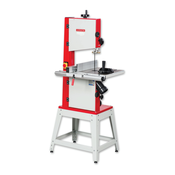
- Page 1 Code 508205 AXMINSTER Hobby SERIES HBS310N 12” Bandsaw...
-
Page 2: Declaration Of Conformity
Index of Contents Page No Index of Contents Declaration of Conformity What’s Included General Instructions for 230V Machines 04-05 Specification Unpacking Stand Assembly Mounting the Bandsaw to the Stand Assembly 08-09 Illustration and Parts Description 10-11-12-13-14-15 Setting Up the Saw 16-17-18-19 Operating Instructions 19-20... -
Page 3: What's Included
What’s Included Quantity Item Model Number MJ343B 1 No. HBS310N 12" Bandsaw (Code: 508205) 1 No. Bandsaw Blade 2,270mm long 4 TPI blade assembled in the saw but not tensioned 1 No. Saw Table 1 No. Fence Guide and Extension 1 No. -
Page 4: General Instructions For 230 V Machines
General Instructions for 230 V Machines Keep the machines clean; it will enable you to more Good Working Practices/Safety easily see any damage that may have occurred. The following suggestions will enable you to Clean the machine with a damp soapy cloth if needs observe good working practices, keep yourself and be, do not use any solvents or cleaners as these may fellow workers safe and maintain your tools and... -
Page 5: Specification
USE YOUR COMMON THIS IS NOT ONE OF THEM. SENSE. Specification Code 508205 Model HBS310N Rating Hobby Power 550W 230V Blade Speed 360 & 720 m/min Blade Length... -
Page 6: Stand Assembly
Unpacking Your saw is packed in the box partially assembled. Take all the easily removable items out of the box, This is to ensure that the components are inserted tip the box up so that the base of the saw is to the in the correct positions. -
Page 7: Mounting The Bandsaw To The Stand
Mounting the Bandsaw to the Stand Lift the saw on to the cabinet, and secure using the 4 M8x40 bolts nuts and washers. ( Insert the bolts through the base of the saw, through the floor cabinet and fit the washers and nuts on the underside). WHEN MOUNTING THE UNIT, WE STRONGLY ADVISE YOU GET THE ASSISTANCE OF ANOTHER PERSON BECAUSE OF THE WEIGHT OF THE MACHINE. - Page 8 Assembly Mounting the saw table The saw table can be fitted without removing the blade, however, if you would feel more comfortable not having to manoeuvre the table around the blade (the table is quite heavy), remove the blade by opening the top and bottom covers and release the tension on the blade by backing off the tensioning wheel.
- Page 9 Assembly Fitting the guide fence Fit the guide fence by clipping the rear clamp over 4 butterfly bolts that secure the blade of the guide the back rail first and dropping the front clamp over fence to the clamping body, adjust and re-tighten. the fence rail, see fig 6 Push down on the lock lever, Larger discrepancies may require that the fence rail and ensure the fence clamps up correctly.
-
Page 10: Illustration And Parts Description
Illustration and Parts Description Blade tensioning wheel Upper door locking knob Upper wheel door Upper blade guide clamp Mitre fence Upper blade guide & guard Guide fence Saw table ‘T’ slot for mitre fence ON/OFF button and switch shroud Fence guide rail Main saw frame Idler wheel adjusting knob Lower wheel door... - Page 11 Illustration and Parts Description Table insert plate Stabilising bolt Mitre fence holder Fore and aft clamping nut (A) Rear thrust bearing (A), Upper bearing blade guides (B) Lateral adjustment clamping grub screws (B) Blade guide bearing adjusting knobs (C) Index marker ON/OFF NVR switch assembly (A) Magnifying glass with index marker Mitre fence assembly (A)
- Page 12 Illustration and Parts Description Micro door switch Upper saw wheel Upper wheel mounting Table insert Saw table Locking lever Lower saw wheel Drive pulley...
- Page 13 Illustration and Parts Description Micro door switch Upper blade guide and guard (A) Idler wheel adjusting knob (A) Upper blade guide drive (B) Lower door lock (B) Lower bearing blade guides (A) Drive pulley (A), Drive belt tensioning idler wheel (B), Drive belt (C) Lower rear thrust bearing (B) Belt tensioning wheel (A), Blade tensioning assembly (C) Upper door lock (A)
- Page 14 Illustration and Parts Description Tracking control knob Upper blade height adjusting wheel Fixing holes for fence extension (NOT SHOWN) Mitre fence Power lead Rear guide rail Table clamping handle Idler wheel adjusting knob 100mm Dust extraction Motor...
- Page 15 Illustration and Parts Description Upper door lock (A), Upper blade guide height clamp (B) Table levelling stop bolt Upper blade guide height adjusting wheel (C), Tracking control knob (D) Tilt quadrant (A), Tilt scale (B) Table clamping handle (D) Tilt scale pointer and adjusting screw (C) 100mm Dust extraction outlet Fence guide bearing assembly...
-
Page 16: Setting Up The Saw
Setting Up the Saw Fig 08 DISCONNECT THE SAW FROM THE MAINS SUPPLY! Blade Tensioning and tracking the blade Make sure both top and bottom blade guides are Tyre well clear of the blade. Open the front covers fully, giving good access to the top compartment of the saw and good visibility into the bottom compartment (see page 12). - Page 17 Setting Up the Saw see fig 14. Retighten the table clamping handle. DISCONNECT THE SAW Fig 14 FROM THE MAINS SUPPLY! Checking the table is square Loosen the clamping handle beneath the table clamping the tilt mechanism, and turn the table hard against its stop.
- Page 18 Setting Up the Saw Fig 16 DISCONNECT THE SAW FROM THE MAINS SUPPLY! Setting the Blade Guides Lower the upper blade guide to approximately 1 1/2”(38mm) above the table. Clamp in place. Loosen the nut (A) holding the guide assembly in place and adjust thefore and aft position so that the leading edges of the side guide bearings are Fig 17...
- Page 19 Setting Up the Saw Fig 19 Fig 20 Rear thrust bearing Lower guide bearing Cap head nut have been made, recheck that when the blade is pressed back against the thrust bearing, both the upper and lower side guides are still behind the teeth of the saw, replace the safety cover. When all adjustments are complete re-connect the power, switch the saw on, allow to run for several minutes, check that the blade is still tracking correctly, there is no excessive vibration, etc.
-
Page 20: Changing The Saw Blade
Operating Instructions 11. If you have to cut very small pieces of material, removed because the machine is to be ‘mothballed’ arrange or manufacture some form of ‘shoe’ to carry for a lengthy time period. (The blade in tension over the timber. - Page 21 Changing the Saw Blade wheel by hand. When you are sure that the blade is Fig 24 “ON” and stable, re-fit the fence guide rail (see fig 24) re-fit the stabilising bolt and re-fit the table insert (see 25-26). Fig 21-22 Fitting the blade Fig 25-26 Stabilising bolt...
-
Page 22: Changing The Blade Speed
Changing the Blade Speed , see figs 29-30. With the drive belt idler wheel back tension removed, very carefully reposition the drive DISCONNECT THE SAW belt (see fig 31). NOTE: Make sure the belt is seated FROM THE MAINS SUPPLY! correctly in one of the drive pulley grooves. - Page 23 Optional Wheel Mobility Kit Optional Wheel Mobility Kit (508207) Fig 34-35 The optional wheel kit provides mobility for the Hobby bandsaw. To assemble follow the instructions below: Step 1 Locate the wheel mobility assembly (J), four M6 bolt, nuts, washers and lifting handle bracket (K).
-
Page 24: Routine Maintenance
Routine Maintenance Daily Monthly • Keep the machine clean. • Open the lower and upper door and check the condition of the tyres and the drive belt (see figs • Check the saw blade for missing teeth and 36-37). cracks (see fig 36). •... -
Page 25: Parts Drawing/List
Parts Drawing/List Continues Over... - Page 26 Parts Drawing/List Description Q’TY Blade Column cover Axis elastic ring Saw body Lower saw wheel Bush Semicircle head screw M4×12 Magnetic switch Lower wheel axle Hexagon head screw M6×16 Hexagon nut M16 Motor Hexagon nut M12 Dust cover Motor wheel Upper door Washer ø16 Lower door...
- Page 27 Parts Drawing/List Description Q’TY Side insert Fixing plate Bearing bar Lower blade guard Bearing 80027 Lower guide base Sliding base Small handle Shaft Hand wheel Locking handle Eccentric shaft Locking block Eccentric bush Plate Washer ø22 Spring piece Hexagon nut M22 Convex window Gear Upper guide board...
- Page 28 Parts Drawing/List Description Q’TY Hex bolt M8X16 Support parts Nut M8 Washer ø8 Rubber legs M8X15 Connected plate (1) Connected plate (2)
-
Page 29: Wiring Diagram
Wiring Diagram... - Page 30 Blades/Accessories Standard Axcaliber Bandsaw Blades Axminster Hobby Series HBS310 & 350N Wheel Kit 2,270mm(89”) x 0.025” An optional wheel kit to provide mobility for the Axminster Hobby Series HBS310N and HBS350N Axminster HBS310N Bandsaw bandsaws. Includes a bolt-on handle for the bandsaw...
- Page 31 Notes...
- Page 32 Hobby, Trade, Industrial, Engineer, Air Tool & CNC Technology Series machines It’s probably the most comprehensive FREE guarantee ever- buy with confidence from Axminster! So sure are we of the quality, we cover all parts and labour free of charge for three years! •...
Need help?
Do you have a question about the HBS310N and is the answer not in the manual?
Questions and answers