Table of Contents
Advertisement
Advertisement
Table of Contents

Related Manuals for Audio Precision APx555


Summary of Contents for Audio Precision APx555
- Page 3 APx555 audio analyzer Installation Instructions and Specifications model APx555 January, 2016...
- Page 4 AUDIO PRECISION, the AUDIO PRECISION logo and the AP logo are trademarks of Audio Precision and are regis- tered in the U.S. Patent and Trademark Office and in other countries. Windows™ is a trademark of Microsoft Corpora- tion.
- Page 5 APx500 measurement software, and in the APx500 User’s Manual, included with the analyzer. The user’s manual is also available as a PDF on the APx500 Application Disc and on the Web at ap.com; additional copies can be ordered from Audio Precision or your local distributor.
-
Page 7: Table Of Contents
APx555 analog I/O specifications ........ - Page 8 Chapter 1: Table of Contents APx555 Audio Analyzer: Table of Contents...
-
Page 9: Safety
3 of qualified. Servicing should be performed only by a quali- this manual. fied technician or an authorized Audio Precision distributor. The International Electrotechnical Commission Do NOT defeat the safety ground connection. This equip-... -
Page 10: Safety Symbols
Do NOT substitute parts or make any modifications with- out the written approval of Audio Precision. Doing so may create safety hazards. Using this product in a manner not specified by Audio Precision can result in a safety hazard. - Page 11 Chapter 1: Safety APx555 Audio Analyzer: Safety Information...
- Page 12 APx555 Audio Analyzer: Installation...
-
Page 13: Installation
PC with these minimum • A color monitor and a video card with at least VGA specifications: capabilities. Video resolution of 1024 x 768 or greater • Operating system: Microsoft Windows 8, Windows 7 or is recommended. Windows Vista. APx555 Audio Analyzer: Installation... - Page 14 From the Instrument Type menu, select an instrument to be The APx555, in particular, can place very high demands on emulated in Demo Mode. the PC system when used in high bandwidth testing.
- Page 15 Hardware Update Wizard to search for the correct software driver. Select “Install the software automatically.” Win- dows will find the Audio Precision driver software installed with APx500 and connect to the instrument. Launch APx500 by double-clicking on the installed short- cut.
- Page 16 Chapter 2: Installation APx555 Audio Analyzer: Installation...
-
Page 17: Abbreviations, Terms And Symbols
Abbreviations, Terms and Symbols used in the following specifications ADC or A/D ..Analog to Digital converter or conversion. BW ....Bandwidth or Measurement Bandwidth, nominally at –3 dB; a single number indicates only the upper limit. - Page 18 Abbreviations, Terms and Symbols...
-
Page 19: Apx555 Analog I/O Specifications
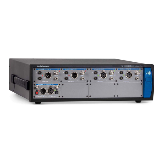
APx555 audio analyzer with APx500 v4.2 or higher measurement software October 2015 NP0020.00022 r002 This illustration shows an APx555 in its standard configuration, with an ADIO module installed. These specifications cover the analog input and output functions of the Audio Precision APx555. - Page 20 20 kHz to 50 kHz ±0.015 dB 50 kHz to 100 kHz ±0.060 dB 100 kHz to 204 kHz ±0.15 dB Settling Time Typically <(40 cycles + 100 ms) to within 0.001 dB of final value APx555 Audio Analyzer: Analog I/O Specifications...
- Page 21 0-21.22 Vrms [60.0 Vpp] bal; 0-10.61 Vrms [30.0 Vpp] unbal & CMT Amplitude Accuracy, 1 kHz ±0.030 dB [±0.35%] +15°C to +30°C ±0.040 dB [±0.46%] 0°C to +45°C Amplitude Setting Resolution Typically <0.001 dB or 0.05 µVrms APx555 Audio Analyzer: Analog I/O Specifications...
- Page 22 Amplitude Flatness 10 Hz to 50 kHz Typically <0.03 dB 50 kHz to 80 kHz Typically <0.10 dB High Cycles (Duration) 1 to 16,777,214 Total Cycles (Interval) 2 to 16,777,215 >4.6 hours at 1 kHz APx555 Audio Analyzer: Analog I/O Specifications...
- Page 23 4:1 based on Vpp Ratio accuracy typically <1.5% 0 to 75.4 Vpp, bal; Amplitude Range 0 to 37.7 Vpp, unbal Amplitude Accuracy ±0.09 dB [±1.0%] –95 dB [0.0018%] 2,3,6 DIM-100 or DIM-30 Residual IMD APx555 Audio Analyzer: Analog I/O Specifications...
- Page 24 Typically <0.015 dB to 20 kHz SR = 8 kS/s to 108 kS/sec Typically <0.010 dB to 20 kHz or 0.45 • SR, whichever is lower Spurious Content Typically <(–100 dB + 0.2 µV) APx555 Audio Analyzer: Analog I/O Specifications...
- Page 25 BNC shield to ground ≈500 Ω || 1 µF 600 ±0.5%, 1.5 W max Terminations automatically open in the Input Terminations 300 ±0.5%, 3.0 W max 80 V and higher input ranges APx555 Audio Analyzer: Analog I/O Specifications...
- Page 26 5 Hz to 200 kHz Tuning Control Generator tracking, Signal must be ≥100 μVrms for input Input tracking, or tracking; F must be within ±0.5% of Fixed (directly entered value) the entered value for fixed tuning. APx555 Audio Analyzer: Analog I/O Specifications...
- Page 27 Typically <–125 dB 40 Hz to 5 kHz Typically <–130 dB 5 kHz to 20 kHz Typically <–120 dB 20 kHz to 50 kHz Typically <–110 dB 50 kHz to 100 kHz Typically <–102 dB APx555 Audio Analyzer: Analog I/O Specifications...
- Page 28 = |F2 - F1| DFD & CCIF diff frequency of 250 Hz–60 kHz and a dif- = (F1 + F2)/2. mean ference frequency of 80 Hz–2.0 kHz [see note 7} ) must be ≥6 mean diff APx555 Audio Analyzer: Analog I/O Specifications...
- Page 29 –90 to +270, ±180, or 0 to 360 deg Accuracy 5 Hz to 5 kHz ±0.15 deg 5 kHz to 20 kHz ±0.6 deg 20 kHz to 50 kHz ±1.5 deg Minimum Input 3 mV APx555 Audio Analyzer: Analog I/O Specifications...
- Page 30 Valid only with DC coupling, both channels. High-pass filters may significantly degrade performance at low fre- quencies. Filter response is relative to “no filter” selection; overall system performance will also include analog flatness imperfections. DSP warping may significantly increase roll-off rate and lower ENBW. APx555 Audio Analyzer: Analog I/O Specifications...
-
Page 31: Adio Specifications
NP0020.00021 rev 003 January, 2016 This illustration shows an APx ADIO module, model 219. These specifications cover the digital input and output functions of the Audio Precision Advanced Digital Input/Output (ADIO). The ADIO is available as a stand-alone module (model 219). - Page 32 Characteristic Specifications Supplemental Information ADVANCED DIGITAL I/O DIGITAL OUTPUT RELATED: Formats Electrical, unbalanced SPDIF-EIAJ per IEC60958 Electrical, balanced AES-EBU per AES3-1992 Optical Toslink® or equivalent Sample Rate (SR) Range Electrical 27 kS/s to 200 kS/s Usable over the extended range of 16 kS/s to 216 kS/s with degraded waveform fidelity, accuracy, and jitter Optical...
- Page 33 Characteristic Specifications Supplemental Information Residual Jitter Unbalanced, Balanced 700 Hz-100 kHz BW ≤600 ps Peak detection 50 Hz-100 kHz BW ≤1.0 ns Peak detection Optical Typically <2.5 ns, SR ≤96 kS/s INTERFACE SIGNAL IMPAIRMENTS Variable Rise/Fall Time Range 12 ns to 100 ns 1 ns typical resolution Accuracy ±(10% + 2 ns)
- Page 34 Characteristic Specifications Supplemental Information Common Mode Signal (Bal only) Waveform Sine Frequency Range 20 Hz to 100 kHz Amplitude Range 0 to 20.0 Vpp, 20 mV steps: ±(10% + 50 mV) EMBEDDED OUTPUT SIGNAL RELATED: Sine, sine split frequency, sine split 8–24 bit word width, triangular PDF Waveforms phase, sine+DC offset, continuously...
- Page 35 Characteristic Specifications Supplemental Information Difference Frequency (Fdiff) 80 Hz to 2.0 kHz = |F2-F1|; diff must be 6 • Fdiff mean Mean Frequency (Fmean) 2.5 kHz to (0.499 • SR – F / 2) or = (F1 + F2)/2 diff mean 60 kHz, whichever is lower...
- Page 36 Characteristic Specifications Supplemental Information Bandwidth Limiting Filters (jitter signals) High-pass 700 Hz (AES3) Special filter conforming with AES3 Butterworth (–3 dB) = 50 Hz to 150 kHz, 4-pole Elliptic (–0.01 dB) = 50 Hz to 150 kHz, 5- pole; 0.01 dB pass-band ripple; ≤–60 dB stop-band Low-pass Butterworth...
- Page 37 Characteristic Specifications Supplemental Information EMBEDDED INPUT SIGNAL RELATED: Level (Amplitude) Measurement Measurement Range < –120 dBFS to +3 dBFS Accuracy (1 kHz) Typically < 0.001 dB Typically < 0.001 dB Flatness Typically < –140 dBFS Residual Noise THD+N Measurement Fundamental Range 5 Hz to 0.49 •...
- Page 38 Characteristic Specifications Supplemental Information IMD Measurement Test Signal Compatibility HF tone must be 6 • LF tone SMPTE & MOD Any combination of 40 Hz–1 kHz (LF) and 1 kHz–60 kHz (HF), mixed in any ratio from 1:1 to 10:1 (LF:HF) Any two-tone combination with mean = (F1 + F2)/2 mean...
- Page 39 Characteristic Specifications Supplemental Information NOTES to SPECIFICATIONS: 1 System specification including contributions from both generator and analyzer subject to the following conditions: (A) SR = 27 kS/s to 200 kS/s, (B) interface signal ≥1.5 Vpp Bal or ≥300 mVpp Unbal, (C) rise-time ≤20 ns, and (D) no impairments.
- Page 40 APx Advanced Digital I/O Module: Specifications...
-
Page 41: Dsio Specifications
October 2015 This illustration shows an APx DSIO module, model 216. These specifications cover the digital serial input and output functions of the Audio Precision DSIO. The DSIO is available as a stand-alone module (model 216), and in a combination mod- ule, combined with DIO (models 111 or 211). - Page 42 Characteristic Specifications Supplemental Information Functional characteristics Channels 1 data line, TDM 1, 2, 4, 6, 8 or 16 Time division multiplexing (TDM) Multiple data lines 1, 2, 4, 6 or 8 up to 4 data lines; 2 channels on each line by TDM S, DSP, custom (left/right justified, Data formats...
- Page 43 Characteristic Specifications Supplemental Information DC characteristics, no load 1.8 volt setting High level input Minimum 1.0 V Low level input Maximum 0.8 V High level output Minimum 1.6 V Low level output Maximum 0.1 V Absolute range Minimum –0.5 V Maximum 5.5 V 2.5 volt setting...
- Page 44 Characteristic Specifications Supplemental Information 3.3 volt setting High level input Minimum 1.8 V Low level input Maximum 1.5 V High level output Minimum 3.0 V Low level output Maximum 0.1 V Absolute range Minimum –0.5 V Maximum 5.5 V Input/Output impedance 50 Ω, nominal All Outputs 10 kΩ, nominal...
- Page 45 Characteristic Specifications Supplemental Information Clock Jitter (Advanced Master Clock required) Jitter Measurement Range 0 to 650 ns Detection Peak, RMS, or Average “Average” detection is recommended for jitter response measurements. Bandwidth Low Limit 50 Hz or 700 Hz High Limit Variable from 1 kHz to 150 kHz in 0.1 kHz steps, Butterworth or Elliptic response...
- Page 46 Characteristic Specifications Supplemental Information NOTES to SPECIFICATIONS 1 System specification including contributions from both generator and analyzer subject to the following condition: Bit Clock 192 kHz. 2 In TDM, channel count can limit the bit clock rate. 3 For Digital Serial (DSIO), the Unit Interval (UI) is defined as 1/fb, where fb is the bitclock rate in hertz. APx Digital Serial I/O Module: Specifications...
-
Page 47: Hdmi+Arc Specifications
October, 2015 This illustration shows the HDMI+ARC module, model 214. These specifications cover the input and output functions of the Audio Precision HDMI+ARC (High Definition Multimedia Interface plus Audio Return Channel) I/O module. HDMI+ARC is available as a stand-alone module (models 114 or 214). - Page 48 Characteristic Specifications Supplemental Information 1.3a + ARC. ARC (Audio Return Channel) imple- Revision mented per HDMI 1.4a Device Connections SOURCE Typically connects to the sink input of The video is an internally generated sin- a DUT. gle color screen or the signal applied to the AUX IN connector.
- Page 49 Characteristic Specifications Supplemental Information HDMI ARC Tx configuration: ARC ARC link can be negotiated or forced on. CEC (ARC connectors) CEC implementation per HDMI 1.4a. User can manually send a CEC ping HDMI ARC Rx configuration: ARC or arbitrary CEC message to any of CEC implementation per HDMI 1.4a.
- Page 50 Characteristic Specifications Supplemental Information EMBEDDED OUTPUT SIGNAL RELATED: Sine, sine split frequency, sine split 8–24 bit word width, triangular PDF Waveforms phase, sine+DC offset, continuously dither. swept-sine, square-wave, noise, IMD signals, multi-tone, constant value, walking ones/zeros, bittest random, wave file playback. Sine Characteristics Frequency Range 5 Hz to 0.499 •...
- Page 51 Characteristic Specifications Supplemental Information DIGITAL INPUT RELATED: Formats Single mode ≤1.5 Vpp Input R is nominally 55 Ω Dual mode ≤1.5 Vpp Input R is nominally 30 Ω 22 kS/s–216 kS/s Typically locks down to 16 kS/s Sample Rate Range EMBEDDED INPUT SIGNAL RELATED: Level (Amplitude) Measurement Measurement Range...
- Page 52 Characteristic Specifications Supplemental Information Elliptic (–0.01 dB) = 10 Hz to 100 kHz, ENBW ≈ (1.012–1.062) • F (varies 8-pole; 0.01 dB pass-band ripple; due to warping) ≤ –60 dB stop-band. Weighting A-wt, B-wt, C-wt, CCIR-1k, CCIR-2k, Weighting filter is cascaded with the CCITT, C-message, 50 μs or 75 μs high-pass and low-pass bandwidth limit- de-emph (with and without A-wt), or...
- Page 53 Characteristic Specifications Supplemental Information Phase Measurement Ranges –90 to +270, ±180, or 0 to 360 deg Typically < 0.001 deg Accuracy Resolution 0.001 deg Notes to Specifications System specification including contributions from both generator and analyzer. Generator-only and analyzer-only contributions are typically less. Sample rate (SR) must be ...
- Page 54 Characteristic Specifications Supplemental Information APx HDMI+ARC I/O Module: Specifications...
-
Page 55: Bluetooth Specifications
NP0020.00015 rev 003 November 2012 This illustration shows the Bluetooth module, model 213. These specifications cover the digital input and output functions of the Audio Precision Blue- tooth interface. Bluetooth is a short-distance (a few meters) control, data, and audio communications wireless technology. - Page 56 Characteristic Specifications Supplemental Information Bluetooth Core Version 2.1+EDR Profiles/Roles Supported A2DP Source With APx-BT-WB hardware module, there is a potential +/- 1 sample inter- channel phase error in A2DP Source or Sink operation. A2DP Sink See note above. HFP Audio Gateway HFP Hands-Free HSP Audio Gateway HSP Headset...
-
Page 57: Pdm Specifications
Decimated Rate. The input bitstream can also be analyzed directly (before decimation) in the Signal Analyzer to view out-of-band components. These specifications cover the digital input and output functions of the Audio Precision PDM interface for the current version, model 228. The PDM module hardware and firmware in model 228 has been changed to provide jitter capabilities and lower logic family voltages. -
Page 58: Technical Specifications
Technical Specifications Parameter Symbol Test Conditions Unit TRANSMITTER Decimated Rate Bit Clock Rate Master or slave mode 0.128 24.576 INTERPOLATION FILTER 16, 16.67, 21.33, 24, 25, 32, 33.33, 37.5, 42.67, 48, 50, 62.5, 64, 66.67, Interpolation Ratio (F INTR 75, 85.33, 96, 100, 125, 128, 150, 192, 200, 250, 256, 300, 384, 400, 500, 512, 600, 768, 800 Passband Frequency Range... - Page 59 Parameter Symbol Test Conditions Unit @OLP; BW = 0.45 F Signal-to-Noise Ratio @MIL; F = 48 kHz; per AES17 Dynamic Range MODULATOR: ORDER 5, 64x OSR Overload Point 1 kHz –9.4 dBFS @OLP; BW = 0.45 F Total Harm. Dist. + Noise –116 @OLP;...
- Page 60 Parameter Symbol Test Conditions Unit MODULATOR: ORDER 4, 512x OSR Overload Point 1 kHz –8.2 dBFS @OLP; BW = 0.45 F Total Harm. Dist. + Noise –130 @OLP; BW = 0.45 F Signal-to-Noise Ratio @MIL; F = 48 kHz; per AES17 Dynamic Range MODULATOR: ORDER 5, 512x OSR Overload Point...
- Page 61 Parameter Symbol Test Conditions Unit LOGIC LEVEL Interface Voltage 0.80 3.30 Resolution 0.01 Accuracy ±0.05 OUTPUT CHARACTERISTICS = 0.5 mA 0.7 • V Output Voltage High LOAD = 0.5 mA 0.3 • V Output Voltage Low LOAD VDD OUTPUT DC Voltage 0.80 3.60 Resolution...
- Page 62 Parameter Symbol Test Conditions Unit Timing Characteristics PDM TRANSMITTER Clock period (master or slave 7813 CLKTX mode) Data hold time / 2-30 Data setup time CLKTX Logic Level = 0.8 V Clock to out Rise Time Fall Time Output Impedance ohms Maximum Clock Frequency 3.072...
- Page 63 Parameter Symbol Test Conditions Unit Logic Level ≥ 2.0 V Clock to out Rise Time Fall Time Output Impedance ohms Maximum Clock Frequency 24.576 PDM RECEIVER Clock period (master or slave 7813 CLKRX mode) Data hold time, rising edge Data hold time, falling edge Data setup time BITCLK DATA TX...
- Page 64 Parameter Symbol Test Conditions Unit Clock Jitter (Advanced Master Clock required) Jitter Measurement Range 0 to 650 ns Detection Peak, RMS or Average Bandwidth Low Limit 50 Hz or 700 Hz Variable in 0.1 kHz steps, High Limit 1 kHz 150 kHz Butterworth or Elliptic response Accuracy (1 kHz)
- Page 65 Parameter Symbol Test Conditions Unit Sine Wave Jitter Frequency Range (f 2 Hz 200 kHz Referenced to bit clock rate, 3.5 UI or 1591 ns Amplitude Range subject to linear derating which ever is less at jitter frequencies >20kHz Amplitude Resolution 100 ps Accuracy (1 kHz) ±0.01%...
- Page 66 APx PDM I/O Module: Specifications...
-
Page 67: Amc Specifications
AMC Advanced Master Clock Rear Panel Sync, Trigger and Ref I/O specifications with APx500 v4.1 or higher measurement software as fitted in APx52x, 555, and 58x audio analyzers NP0020.00023 rev 001 January 2015 This illustration shows a section of the APx rear panel, focusing on the Auxiliary I/O and the Sync, Trigger and DARS reference connections for the AMC. - Page 68 Characteristic Specifications Supplemental Information REAR PANEL I/O Auxiliary Digital Control Output 8 bits Typically 0-5V, 9-pin male D-sub Input 8 bits Internal pull-up, 9-pin female D-sub Sync Input Signal Compatibility Square or Sine Voltage Range 0.8 Vpp to 5.0 Vpp >10 kΩ, AC coupled Frequency Range 4 kHz to 50 MHz, square;...
- Page 69 Characteristic Specifications Supplemental Information Trigger Input Voltage Range –0.5 V to +5.5 V Threshold Level +0.8 to +3.6 V, 0.1 V steps ≈10 kΩ, DC coupled, + or – edge selectable Minimum Pulse Width Typically 20 ns Trigger Output Trigger Sources Analog Sine Generator, Audio Gener- ator, and Jitter Generator Amplitude (V...
- Page 70 APx AMC Sync, Trigger and Ref Input/Output Specifications...
-
Page 71: General And Environmental Specifications
Max Operating Altitude 20 minutes Allow up to 1 hour per 10°C if unit has Stabilization Time been exposed to a significant change in temperature. Allow 24–48 hours to recover if condensation has occurred. APx555 Audio Analyzer: General and Environmental... - Page 72 Dimensions (W, H, D) 17.0 in, 5.08 in, 18.7 in 10.8 kg [23.8 lbs] with no digital inter- Add ≈ 0.2 kg [0.4 lbs] for each digital Weight face options installed interface option installed. APx555 Audio Analyzer: General and Environmental...
Need help?
Do you have a question about the APx555 and is the answer not in the manual?
Questions and answers