Themis RES-22XR3 Installation Manual
2ru 19” rack-mount rugged enterprise server with x8dtn+ motherboard configuration /two quad/dual-core 5500 or quad/six-core 5600 xeon cpus
Hide thumbs
Also See for RES-22XR3:
- Installation manual (144 pages) ,
- Installation manual (162 pages) ,
- Installation manual (142 pages)
Table of Contents
Advertisement
Quick Links
Download this manual
See also:
Installation Manual
Advertisement
Table of Contents

Related Manuals for Themis RES-22XR3


Summary of Contents for Themis RES-22XR3
- Page 1 User Manual User Manual Installation Installation Manual Manual 2RU 19” Rack-Mount Rugged Enterprise Server with X8DTN+ Motherboard Configuration / Two Quad/Dual-Core 5500 or Quad/Six-Core 5600 Xeon CPUs ®...
- Page 3 RES-22XR3 Installation Manual - Configuration 4* Version 1.1— March 2012 * SuperMicro Motherboard X8DTN+ Themis Computer—Americas and Pacific Rim Themis Computer—Rest of World 47200 Bayside Parkway 5 Rue Irene Joliot-Curie Fremont, CA 94538 38320 Eybens, France Phone (510) 252-0870 Phone +33 476 14 77 80...
-
Page 4: Safety Precautions
Themis Computer ass umes no resp onsibility for inaccuraci es. Themis Computer retains the right to make changes to this publication at any time wit hout prior notice. Themis Computer does not assume any liability arising from the application or use of this publication or the product(s) described herein. - Page 5 • Corrected all instances within the text referring to the RES-22X R3 Configuration 4 as bei ng 3RU in height. • added caution to Appendix F, “Re-packaging for Shipment” regarding shipping the RES-22XR3 Configuration 4 in o riginal Themis Packaging.
-
Page 6: Safety Instructions
In these cases, the device must be shut down and secured against unintentional operation. • Repairs may only be carried out by a person authorized by Themis Computer. • The device may only be opened for the installation and removal of extension... -
Page 7: Grounding Methods
4. Store electrostatic-sensitive boards in protective packaging or on conductive foam. Grounding Methods Guard against electrostatic damage at workstations by following these steps: 1. Cover workstations with approved anti-static materi al. Provide a wrist strap connected to a work surface and properly grounded tools and equipment. Themis Computer... - Page 8 RES-22XR3 Installation Manual - Configuration 4 Version 1.1 2. Use anti-static mats, heel straps, or air ionizers to give added protection. 3. Handle electrostatic-sensitive components, boards, and assemblies by the case or the PCB edge. 4. Avoid contact with pins, leads, or circuitry.
-
Page 9: Table Of Contents
1.8.2.1 System Power ................1-16 1.8.2.2 Output Voltage ................1-17 1.8.3 Environmental ..................1-17 1.8.3.1 Shock ..................1-17 1.8.3.2 Electrostatic Discharge ............. 1-17 1.8.3.3 Noise ..................1-17 1.9 Packaging and Shipping ..................1-19 1.9.1 Accessory Kit ................... 1-19 Themis Computer... - Page 10 RES-22XR3 Installation Manual - Configuration 4 Version 1.1 1.9.2 Rack-Mount Slides (Optional) ..............1-20 2. Installation and Operation ................... 2-1 2.1 Installation Procedures ................... 2-1 2.1.1 Remove Protective Top Cover ..............2-1 2.1.2 Memory Modules ..................2-3 2.1.2.1 Installation .................. 2-4 2.1.3 PCI Cards ....................
- Page 11 3.3.3.12 Intel® C-STATE Tech ..............3-9 3.3.3.13 C3 State ..................3-9 3.3.3.14 C6 State ..................3-9 3.3.3.15 C-State package limit setting ............3-9 3.3.3.16 C1 Auto Demotion ..............3-9 3.3.3.17 C3 Auto Demotion ..............3-10 3.3.3.18 Clock Spread Spectrum ............3-10 Themis Computer...
- Page 12 RES-22XR3 Installation Manual - Configuration 4 Version 1.1 3.3.4 Advanced Chipset Control ............... 3-10 3.3.4.1 QPI (Quick Path Interconnect) Links Speed ......3-10 3.3.4.2 QPI Frequency ................3-10 3.3.4.3 QPI L0s and L1 ................. 3-10 3.3.4.4 Memory Frequency ..............3-10 3.3.4.5 Memory Mode ................
- Page 13 3.3.13.3 ACPI APIC Support ..............3-24 3.3.13.4 APIC ACPI SCI IRQ ..............3-24 3.3.13.5 Headless Mode ................3-25 3.3.13.6 NUMA Support ................. 3-25 3.3.13.7 ACPI SLIT Table ..............3-25 3.3.13.8 High Performance Event Timer ..........3-25 3.3.13.9 WHEA Support ................. 3-25 Themis Computer...
- Page 14 RES-22XR3 Installation Manual - Configuration 4 Version 1.1 3.3.14 Trusted Computing .................. 3-25 3.3.14.1 TCG/TPM (Trusted Platform Module) Support ....... 3-25 3.3.15 Event Log Configuration ................. 3-26 3.3.15.1 View Event Log ................ 3-26 3.3.15.2 Mark all Events as Read ............3-26 3.3.15.3 Clear Event Log ................
- Page 15 E.1 Ordering the RES Audio/USB/Serial Port Custom Module ........E-7 Appendix F. Re-packaging Instructions ................. F-1 F.1 Re-packaging for Shipment ................... F-1 F.2 Packaging Components ..................F-2 F.3 Instructions for Re-packaging ................F-3 Index ..........................Index-1 Reader Comment Card xiii Themis Computer...
- Page 16 RES-22XR3 Installation Manual - Configuration 4 Version 1.1 Themis Computer...
- Page 17 X8DTN+ Motherboard Block Diagram............1-3 Figure 1-2 External Features of the RES-22XR3 (Front and Rear) ........1-4 Figure 1-3 Major Components of RES-22XR3 Configuration 4 (Open Top View) ..1-5 Figure 1-4 RES-22XR3 System LEDs and I/O Connectors (X8DTN+ Motherboard) ..1-6 Figure 1-5 RES-22XR3 with Front Sound Baffle Installed (Front View) ......
- Page 18 RES-22XR3 Installation Manual - Configuration 4 Version 1.1 AC Power Socket and LED on the RES-22XR3 Rear........2-18 Figure 2-15 System Power Button and LED on the RES-22XR3 Front ......2-18 Figure 2-16 Main BIOS Setup Screen ................. 3-3 Figure 3-1 BIOS Setup Utility Screen ................
- Page 19 Front I/O 16”-Deep Chassis Manual Matrix........... xxii Table 3 RES-22XR3 Configuration 4 Motherboard Options ........1-2 Table 1-1 Major Features of RES-22XR3 Configuration 4 ..........1-2 Table 1-2 System LEDs ....................1-7 Table 1-3 Power Supply LED Behavior ................. 1-8...
- Page 20 RES-22XR3 Installation Manual - Configuration 4 Version 1.1 Rear-Panel I/O Connectors ................1-9 Table 1-5 RES-22XR3 General Specifications ............. 1-15 Table 1-6 RES-22XR3 Configuration 4 Electrical Specifications........ 1-16 Table 1-7 Approximate Weights of the RES Series............1-20 Table 1-8 RES-22XR3 Memory Capacity ..............2-3 Table 2-1 RES-22XR3 Memory Population ..............
-
Page 21: Preface
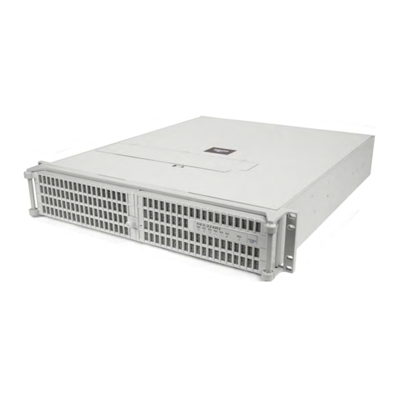
Preface This document, entitled RES-22XR3 Installation Manual—Configuration 4, pro- vides instructions on how to install, configure, power up, and boot the Themis Rug- ged Enterprise Server RES- 22XR3 Configuration 4 (see Figure 1), which is based on two Intel ®... -
Page 22: Table 1 Res-X2Xr3 20"-Deep Chassis Manual Matrix
RES-22XR3 Installation Manual - Configuration 4 Version 1.1 Table 1. RES-x2XR3 20”-Deep Chassis Manual Matrix RES-22XR3 RES-32XR3 RES-22XR3 RES-12XR3 with Riser Category Motherboard Manual Manual Manual Manual kets Part Number Part Number Part Number Part Number X8DTH-iF Configuration 1 116790-024... -
Page 23: Table 2 Res-X2Xr3S / Res-X1Xr3 17"-Deep Chassis Manual Matrix
LN4 = Extra gigabit Ethernet controller for two extra ports z: F = IPMI blank = No IPMI a—The 17”-deep RES XR3 chassis actually measures 17.07” deep, but for simplicity will continue to be referred to as being 17” deep through- out these manuals. Themis Computer... -
Page 24: Figure 2 Front View Of A Standard Rear-I/O Res-22 Chassis (Doors Removed)
RES-22XR3 Installation Manual - Configuration 4 Version 1.1 A matrix describing RES chassis configur ed for front-I/O c onnector and front-PCI card access in a 16”-deep chassis is given in Table 3. This chassis design makes it more convenient to install cables to the system and demands no access to the rear of the chassis except to replace a fan. -
Page 25: Figure 3 Rear View Of A Standard Rear-I/O Res-22 Chassis
Preface Figure 3. Rear View of a Standard Rear-I/O RES-22 Chassis Figure 4. Front View of a Front-I/O RES-32 Chassis Figure 5. Rear View of a Front-I/O RES-32 Chassis xxiii Themis Computer... - Page 26 RES-22XR3 Installation Manual - Configuration 4 Version 1.1 The 2RU-high (3.5”) RES-22XR3 Configuration 4 has been designed to fit into a standard 19” rack and is provided wi th rack-mount brackets with handles. Optional rack-mount slides are also available. The RES-22XR3 Configuration 4 is rugged enough to withstand extreme shock (up to 35G), temperature (up to 55°C operating),...
- Page 27 To reduce the risk of elec- trical shock and danger, follow the instructions accompanying this symbol. Sidebar: A “sidebar” adds detail to th e section within which it is placed, but is not absolutely vital to the description or procedure of the section. Themis Computer...
- Page 28 RES-22XR3 Installation Manual - Configuration 4 Version 1.1 xxvi Themis Computer...
-
Page 29: Overview And Specifications
Overview and Specifications Overview The RES-22XR3 Configuration 4 (see Figure 1-1 below; a block diagram is given in Figure 1-2 on page 1-3) is a rack-mounted system designed specifically for above-average shock and vi bration environments. The RES-22XR3 supports dual Intel ®... -
Page 30: Table 1-1 Res-22Xr3 Configuration 4 Motherboard Options
64-bit, 133-MHz PCI-X slot (3), and two 64-bit, 133/100-MHz PCI-X slots. f—One PCI-e 2.0 x8 in a UIO slot. The RES-22XR3 Configuration 4 is designed within a 2RU-high (3.5”) form-factor 20” (50.8 cm) deep and 17” (43.2 cm) wide (which, with mounting brackets, fits a 19”- wide rack). -
Page 31: Figure 1-2 X8Dtn+ Motherboard Block Diagram
RJ45 Intel 5520 Ports Ports Ports 9,10 CLINK Chnl A SST25 VF016 Chnl B CLINK JMB368 ICH10R SATA #1 83627 SATA #2 SATA #3 SATA #4 SATA #5 ES1000 Floppy SATA #6 Figure 1-2. X8DTN+ Motherboard Block Diagram Themis Computer... -
Page 32: Figure 1-3 External Features Of The Res-22Xr3 (Front And Rear)
PCI-Express 2.0 x8 slot Figure 1-3. External Features of the RES-22XR3 (Front and Rear) The RES-22XR3 front panel houses eight storage drive bays to accommodate up to eight removable storage drives. The motherboard supports up to 6 SATA2 devices— both storage drives and the DVD-ROM combo drive—but more devices may be added by installing an optional SATA or SAS controller card in an available PCI slot of the system. -
Page 33: Figure 1-4 Major Components Of Res-22Xr3 Configuration 4 (Open Top View)
1—Overview and Specifications Overview Major features of the RES-22XR3 are described in Table 1-2, page 1-2. Major inter- nal components can be seen in the open top view (cover removed) of Figure 1-4. Power Supply (1 of 2) Air-Flow Deflector... -
Page 34: System Leds And I/O Connectors
Version 1.1 System LEDs and I/O Connectors All RES-22XR3 system LEDs are located on the front panel (see A, Figure 1-5); all I/O connectors are located on the rear panel (see B, Figure 1-5). LEDs are described in Table 1-3 on page 1-7; I/O connectors are described in Table 1-5, page 1-9. -
Page 35: Table 1-3 System Leds
The color of the left LED (when facing the port) indicates the LAN connection speed: - Off = 10 MHz LAN1 and LAN2 - Green = 100 MHz - Amber = 1 GHz The right LED, when lit, indicates LAN activity. a—NIC = Network Interface Controller. Themis Computer... -
Page 36: Table 1-4 Power Supply Led Behavior
RES-22XR3 Installation Manual - Configuration 4 Version 1.1 Table 1-4. Power Supply LED Behavior Symbol LED Power System LED Description If system is powered on, Power Fail LED warns that the upper power (Left Power Supply) (red LED) supply has failed or has Note: system is powered on lost AC input. -
Page 37: Table 1-5 Rear-Panel I/O Connectors
Note: A second serial port—COM2—can be accessed directly from the motherboard. One DE-15 3x5 (15-pin) Video Graphics Array connector to attach a VGA Port VGA display. Two Gigabit Ethernet Standard RJ45 connectors to attach one or two gigabit Ethernet LAN LAN Ports line(s)—LAN1 and LAN2. Themis Computer... -
Page 38: Chipset Overview
Chipset Overview Built upon the functionality and the capability of the Intel 5500/5600 CPU platform, RES-22XR3 Configuration 4 motherboards provide the performance and feature sets required for dual processor-based high-end systems, including optimal configuration options for communications, high-end CAD systems, presentation, storage, compu- tation or database applications. -
Page 39: Special Features
CPU temperature is too high, it will automatically turn on the thermal fan control to prevent any overh eat damage to the CPU. The on board chassis thermal circuitry can monitor the overall system temperature and alert users when the chassis temperature is too high. 1-11 Themis Computer... -
Page 40: System Resource Alert
RES-22XR3 Installation Manual - Configuration 4 Version 1.1 Caution: To avoid possible system overheating, please be sure to provide adequate airflow to your system. 1.5.3 System Resource Alert This feature is available when used with Supero Doctor III in the Windows OS envi- ronment or used with the Supero Doctor II in Linux. -
Page 41: Main Switch Override Mechanism
3-pin header on a Network Interface Card (NIC) that has WOL capa- bility. In addition, an onboard LAN contro ller can also suppor t WOL without any connection to the WOL header . The 3-pin WO L header is to be used with a LAN add-on card only. 1-13 Themis Computer... -
Page 42: Super I/O Controller
RES-22XR3 Installation Manual - Configuration 4 Version 1.1 Super I/O Controller The Super I/O chip storage-drive adapter functions include: • a floppy storage drive controller (industry standard 82077/765 compatible) • a data separator • write pre-compensation circuitry • decode logic •... -
Page 43: Specifications
1—Overview and Specifications Specifications 1.8.1 General Table 1-6 lists general specifications for the RES-22XR3. Table 1-6. RES-22XR3 General Specifications Parameter Description Dimensions 3.5” (2RU) high 17” (43.2 cm) wide (19” rack-mountable) 20” (50.8 cm) deep Weight ... -
Page 44: Electrical
(SVS5-4 or equivalent) a—These are “typical” results from a RES system. Please contact Themis for information regarding your exact system configuration. b—Tested using a watt meter with a SuperMicro X8DA3 Motherboard, with a nVidia GeForce 9600 GT graphics card, Intel Dual/Quad- Core X5550 CPU @ 2.66GHz, and 32GB of RAM. -
Page 45: Output Voltage
(muffler) on both the front (see Figure 1-6) and the rear (see Figure 1-7 on page 1-18) of the RES-22XR3 chassis. Call your Themis representative for additional information. ( Figure 1-6 and Figure 1-7 on page 1-18 illustrate sound baffles installed on a RES-22XR3 chassis.) -
Page 46: Figure 1-7 Res-22Xr3 With Rear Sound Baffle Installed (Rear View)
Version 1.1 Note: All RES systems are shipped with BIOS fan speed set to the quietest mode. The default fan speed control mode of the RES-22XR3 Configuration 4 is Energy Saving/ES. Front Access—Opening the two front doors of the RES-22XR3 requires removing the front sound baffle. -
Page 47: Packaging And Shipping
A. Two AC Power Cords B. Two Front-Bezel (Door) Barrel Keys When you unpack the RES-22XR3 Configurati on 4, please verify that all of these items are included. If any of these items ar e missing, please call Themis Technical Support at 510-252-0870, or send an email to support@themis.com. -
Page 48: Rack-Mount Slides (Optional)
1.9.2 Rack-Mount Slides (Optional) Rack-Mount Slides can be mounted on each side of the RES-22XR3 Configuration 4 for the purpose of sliding the unit in and out of a rack. Mounting slides are optional and can be ordered at the time of purchase. -
Page 49: Installation And Operation
• How to install a memory module, st orage drive, PCI card, 80-mm-fan, power supply, and lithium battery. • Rack-mount brackets and slides • How to turn the RES-22XR3 Configuration 4 on and off Installation Procedures Caution: Use industry-standard ESD groundi ng techniques when handling all components. -
Page 50: Figure 2-1 Remove The Res-22Xr3 Protective Access Cover
1. Loosen the two captive Phillips scre ws holding the protective top access cover to the rear of the RES-22XR3 chassis (see A, Figure 2-1). 2. Both the front and sides of the cover have flat hooks or tabs underneath that fit under slots on the chassis top edges (see B, Figure 2-1). -
Page 51: Memory Modules
2—Installation and Operation Installation Procedures 2.1.2 Memory Modules The RES-22XR3 Configuration 4 supports memory according to Table 2-1 and dis- tributed according to Table 2-2. Table 2-1. RES-22XR3 Memory Capacity Memory Parameters DDR3 Motherboard Number Pins per Capacity Registered Speed (MHz) -
Page 52: Installation
1. Loosen and remove the eight screws securing the air-flow deflector (see Fig- ure 2-2). 2. Select the memory slot that you wish to install a new Memory Module (see Figure 2-3 on page 2-5). Figure 2-2. Remove RES-22XR3 Air-Flow Deflector (X8DTN+ Motherboard) Themis Computer... -
Page 53: Figure 2-3 Memory Module Slot Locations (X8Dtn+ Motherboard)
(see Figure 2-4 on page 2-6), then pulling the old module directly up from the slot until it is free of the connector. Themis Computer... -
Page 54: Figure 2-4 Memory Module Removal
RES-22XR3 Installation Manual - Configuration 4 Version 1.1 Press latch downward & outward at each end Figure 2-4. Memory Module Removal 4. Before inserting a new memory module in to the vacant slot, make sure that the two latches—one at each end—are pulled outward away from the center of the slot (see Figure 2-4). -
Page 55: Pci Cards
Installation Procedures 2.1.3 PCI Cards The RES-22XR3 Configuration 4 supports the PCI slots indicated in Figure 2-5. All slots support cards up to 12.28- inches long. Remember that slots 0 and 7 cannot be accessed through the rear I/O panel. -
Page 56: Lithium Battery
Latch To release, squeeze battery latch together… … and remove battery from socket Figure 2-6. The RES-22XR3 Lithium Battery and Socket 2.1.4.2 Installing a Lithium Battery Perform the following steps to insert a new lithium battery: 1. Tilt the replacement battery into the empty socket so that it is angled under the battery latch (see B, Figure 2-6). -
Page 57: Storage Drives
To access the removable storage drives, you must first open the two front doors (see Figure 2-7). The knurled captive screw on the fr ont of the RES-22XR3 allows the doors to lock without a key . To unlock the doors, turn the screw counterclockwise and pull both doors away from the chassis. -
Page 58: Storage-Drive Removal
Version 1.1 2.1.5.2 Storage-Drive Removal The accessory kit shipped with your RES-22XR3 Configuration 4 contains two bar- rel lock keys. This provides you the option of unlocking/locking the storage drives. After opening the front doors, perform the following step s to remove and install a... -
Page 59: Storage-Drive Installation
The handle will swing closed when it comes into contact with the RES-22XR3 chassis. 4. When the drive is fully inserted in its slot, insert the key into the barrel lock and turn it 45 degrees counter-clockwise. -
Page 60: Removable 80-Mm Fan
The RES-22XR3 contains three high-speed 80-mm fans. All fans are hot-swappable in case of a fan failure. Note: Since RES-22XR3 Configuration 4 fans are “hot-swappable”, it is not nec- essary to turn off system power in order to remove and replace a fan. -
Page 61: Figure 2-11 Fan Lid Lock
With the right hand index finger , press on the right hand side of the fan and pull the fan directly upward from the RES-22XR3 chassis. 3. When the fan is removed, its 4-wire connector will be disconnected from the chassis. -
Page 62: Power Supply
RES-22XR3 Installation Manual - Configuration 4 Version 1.1 Figure 2-11, page 2-13) to engage the Locking contact area (see Figure 2-12 below) onto the locking stud. Locking Contact Area Rear of System Font of System Figure 2-12. Locking Contact area 2.1.7... -
Page 63: Figure 2-13 The Res-22Xr3 Power Supply Locking Mechanism
(for knurled captive screw Power Supply on power supply bracket) System Power LED Locking Lever Phillips Screw Hole (for knurled captive screw on power supply bracket) AC Outlet Extraction Handle Figure 2-13. The RES-22XR3 Power Supply Locking Mechanism 2-15 Themis Computer... -
Page 64: Installing A Power Supply
RES-22XR3 Installation Manual - Configuration 4 Version 1.1 2.1.7.2 Installing a Power Supply Perform the following steps to install a power supply: 1. Insert the replacement power supply into an empty slot with the extraction handle facing to the left (see Figure 2-13 on page 2-15). -
Page 65: Rack Mounts
To learn how to install r ack-mount slides, refer to A ppendix B, “Rack-Mount Slide Installation”. Caution: Any screws used to mount a slide to a RES-22XR3 chassis must not ex- ceed a length of 3/8” to prevent excessive penetration of the chassis. -
Page 66: Operation
Before powering on the RES-22XR3, plug in the AC power cords as follows: 1. On the rear of the RES-22XR3, plug an AC power cord (shipped with unit) into the AC power socket on each power supply (see Figure 2-15). -
Page 67: Getting Started
1. To turn the RES-22XR3 power of f, press and hold the system power on/of f button (see Figure 2-16, page 2-18) for at least four (4) seconds. This will shut down the system and turn of f the POWER LED as well as the rear power supply LED. -
Page 68: Res-22Xr3 Installation Manual - Configuration 4 Version
RES-22XR3 Installation Manual - Configuration 4 Version 1.1 2-20 Themis Computer... -
Page 69: Bios Setup Utility
BIOS Setup Utility Introduction This chapter describes the AMI BIOS Setup Utility for the RES-22XR3 Configura- tion 4 motherboard. The AMI ROM BIOS is stored in a Flash EEPROM and can be easily updated. This chapter describes the basic navigation of the AMI BIOS Setup Utility setup screens. -
Page 70: How To Change The Configuration Data
Flashing the wrong BIOS can cause irreparable damage to the system. In no event shall Themis Computer be liable for direct , indirect, special, incidental, or conse- quential damages arising from a BIOS update. If you have to update the BIOS, do not shut down or reset the system while the BIOS is updating. -
Page 71: Main Bios Setup
<Enter>. Press the <Tab> key to move betw een fields. The date must be entered in Day MM/DD/YY format. The time is entered in HH:MM:SS format. Note: The time is in the 24-hour format. For example, 5:30 P.M. appears as 17:30:00.). Themis Computer... -
Page 72: Super Micro X8Dtn
RES-22XR3 Installation Manual - Configuration 4 Version 1.1 3.2.1.2 Super micro X8DTN+ • BIOS Build Version: This item displays the BIOS revision used in your sys- tem. • BIOS Build Date: This item displays the date when this BIOS was completed. -
Page 73: Advanced Setup Configurations
This option allows the bootup screen options to be m odified between POST mes- sages or the OEM logo. Sel ect Disabled to display the POST messages. Select Enabled to display the OEM logo inst ead of the normal PO ST messages. The options are Enabled (default) and Disabled. Themis Computer... -
Page 74: Addon Rom Display Mode
RES-22XR3 Installation Manual - Configuration 4 Version 1.1 3.3.1.3 AddOn ROM Display Mode This sets the display mode for the Option ROM. Select Keep Current to use the cur- rent AddOn ROM Display se tting. Select Force BIOS to use the Option ROM dis- play mode set by the system BIOS. -
Page 75: Restore On Ac Power Loss
3.3.3.4 Adjacent Cache Line Prefetch (Available when supported by the CPU) The CPU prefetches the cache line for 64 bytes if this option is set to Disabled. The CPU prefetches both cache lines for 128 bytes as comprised if Enabled (default). Themis Computer... -
Page 76: Mps And Acpi Madt Ordering
RES-22XR3 Installation Manual - Configuration 4 Version 1.1 3.3.3.5 MPS and ACPI MADT Ordering This feature allows the user to confi gure the MPS (Multi-Processor Specification) and ACPI settings for your motherboard. Select modern ordering if Windows XP or a newer version of Windows OS is used in the motherboard. Select Legacy Ordering if Windows 2000 or an earlier version of Windows OS is used. -
Page 77: Intel® Eist Technology
The options are Auto (default), C1, C3, C6 and C7. 3.3.3.16 C1 Auto Demotion When this feature is enabled, the CPU will conditionally de mote C3, C6 or C7 requests to C1 based on un-core auto-dem ote information. The options are Disabled and Enabled (default). Themis Computer... -
Page 78: C3 Auto Demotion
RES-22XR3 Installation Manual - Configuration 4 Version 1.1 3.3.3.17 C3 Auto Demotion When this feature is enabled, the CPU will conditionally demote C6 or C7 requests to C3 based on un-core auto-demote in formation. The options are Disabled and Enabled (default). -
Page 79: Memory Mode
C increment. The default is [006]. Press “+” or “- ” on your keyboard to change this value. Inlet Temperature This is the temperature detected at the chassis inlet. Each step is in 0.5 C increment. The default is [070]. Press “+” or “-” on your keyboard to change this value. 3-11 Themis Computer... -
Page 80: Air Flow
RES-22XR3 Installation Manual - Configuration 4 Version 1.1 Temperature Rise This is the temperature rise to the DI MM thermal zone. Each step is in 0.5 C incre- ment. The default is [020]. Press “+” or “-” on your keyboard to change this value. -
Page 81: Dca (Direct Cache Access)
Please refer to your add-on card user guide fo r the desired setting. The options are 256B (default) and 128B. 3.3.6 Southbridge Configuration This feature allows the user to configure the settings for the Intel ICH Southbridge chipset. 3-13 Themis Computer... -
Page 82: Usb Functions
RES-22XR3 Installation Manual - Configuration 4 Version 1.1 3.3.6.1 USB Functions Select the number of onboard USB ports to be enabled. The Options are: Disabled and Enabled (default). (If this item is se t to Enabled, the USB 2.0 Controller will be enabled.) -
Page 83: I/O Port Decode
Select Intel to enable Intel’s SATA RAID firmware to configure Intel’s SATA RAID settings. Select Adaptec to enable Adaptec’s SATA RAID firmware to conf igure Adaptec’s SATA RAID settings. The options are Intel (default) and Adaptec. 3-15 Themis Computer... -
Page 84: Sata#2 Configuration
RES-22XR3 Installation Manual - Configuration 4 Version 1.1 3.3.8.2 SATA#2 Configuration (This feature is available when IDE is se- lected) Selecting Enhanced will set SA TA#2 to native SATA mode. The options are Dis- abled, and Enhanced (default). 3.3.8.3 Primary IDE Master/Slave, Secondary IDE Master/Slave, Third... -
Page 85: Dma Mode
4.2 MB/s MWDMA 1 Multi-Word DMA 1 13.3 MB/s MWDMA 2 Multi-Word DMA 2 16.6 MB/s UDMA 0 Ultra DMA 0 16.6 MB/s UDMA 1 Ultra DMA 1 25 MB/s UDMA 2 Ultra DMA 2 33.3 MB/s 3-17 Themis Computer... -
Page 86: Ide Detect Timeout (Sec)
RES-22XR3 Installation Manual - Configuration 4 Version 1.1 Table 3-2. DMA Mode Select Options (Continued) Option Selected DMA Mode Max. Transfer Rate UDMA 3 Ultra DMA 3 44.4 MB/s UDMA 4 Ultra DMA 4 66.6 MB/s UDMA 5 Ultra DMA 5... -
Page 87: Pci Latency Timer
This feature allows the user to sel ect the onboard LAN opt ion ROM type. The options are iSCSI and PXE (default). 3.3.9.9 Boot Graphics Adapter Priority This feature allows the user to select the priority gra phics adapter for system boot. The options are Onboard VGA and Offboard VGA (default). 3-19 Themis Computer... -
Page 88: Super Io Device Configuration
RES-22XR3 Installation Manual - Configuration 4 Version 1.1 3.3.10 Super IO Device Configuration 3.3.10.1 Onboard Floppy Controller Select Enable to enable the onboa rd Floppy Controller. The options are Enabled (default) and Disabled. 3.3.10.2 Serial Port1 Address/ Serial Port2 Address This option specifies the ba se I/O port address and the Interrupt Request address of Serial Port 1 and Serial Port 2. -
Page 89: Serial Port Mode
The options are No Delay (default), Delay 1 Sec, Delay 2 Sec, and Delay 4 Sec. 3.3.12 Hardware Health Configuration This feature allows the user to monitor system health and review the status of each item as displayed. 3-21 Themis Computer... -
Page 90: Cpu Overheat Alarm
RES-22XR3 Installation Manual - Configuration 4 Version 1.1 3.3.12.1 CPU Overheat Alarm This option allows the user to select the CPU Overheat Alarm setting which deter - mines when the CPU OH alarm will be act ivated to provide warning of possible CPU overheat. -
Page 91: System Temperature
3.3.12.3 System Temperature The system temperature will be displayed (in degrees in Celsius and Fahrenheit) as it is detected by the BIOS. 3.3.12.4 Fan Speed Readings This feature displays the fan speed readings from Fan1 through Fan8. 3-23 Themis Computer... -
Page 92: Fan Speed Control Monitor
RES-22XR3 Installation Manual - Configuration 4 Version 1.1 3.3.12.5 Fan Speed Control Monitor This feature allows the user to decide how the system controls the speeds of the onboard fans. The CPU temperature and the fan speed are correlative. When the CPU on-die temperature increases, the fan speed will also increase for effective system cool- ing. -
Page 93: Headless Mode
Select Yes on this item and enable the TPM ju mper on the motherboard to enable TCG (TPM 1.1/1.2)/TPM support in order to improve data inte grity and network security. The options are No (default) and Yes. If this feature is set to Yes, the fol- lowing items will display: 3-25 Themis Computer... -
Page 94: Tpm Owner Status
RES-22XR3 Installation Manual - Configuration 4 Version 1.1 Execute TPM Command Select Enabled to execute TPM command s you’ve selected. Select Don’t change to keep the current TPM commands without making any changes. Select Disabled to abandon the changes you have made on TP M commands. The options are Enabled, Disabled and Don’t Change (default). -
Page 95: Security Settings
This item indicates if a user passwor d has been entered for the system. “Not Installed” means that a user password has not been used. 3.4.3 Change Supervisor Password Select this feature and press <Enter> to enter a new Supervisor Password. 3-27 Themis Computer... -
Page 96: Change User Password
RES-22XR3 Installation Manual - Configuration 4 Version 1.1 3.4.4 Change User Password Select this feature and press <Enter> to access the submenu, and then en ter a new User Password. 3.4.5 Clear User Password (Available only if User Pass- word has been set) This item allows you to clear a user password after it has been entered. -
Page 97: Boot Configuration
This feature allows the user to specify the boot sequence from available Removable Drives. The settings are 1st boot device, 2nd boot device, and Disabled. • 1st Drive - [1st Floppy Drive] • 2nd Drive - [USB: XXXXXXXXX] 3-29 Themis Computer... -
Page 98: Storage Drives
RES-22XR3 Installation Manual - Configuration 4 Version 1.1 3.5.3 Storage Drives This feature allows the user to s pecify the boot sequence from all available storage drives. The settings are Dis abled and a lis t of all storage drives that have been detected (i.e., 1st Drive, 2nd Drive, 3rd Drive, etc). -
Page 99: Exit Options
Discard Changes and Exit Select this option to quit the BIOS Set up without making any permanent changes to the system configuration, and reboot the computer. Select Discard Changes and Exit from the Exit menu and press <Enter>. 3-31 Themis Computer... -
Page 100: Discard Changes
RES-22XR3 Installation Manual - Configuration 4 Version 1.1 3.6.3 Discard Changes Select this option and press <Enter> to discard all the changes and return to the AMI BIOS Utility Program. 3.6.4 Load Optimal Defaults To set this f eature, select Load Optima l Defaults from the Exit menu a nd press <Enter>. -
Page 101: Bios Recovery
Insert the USB device that contains the new BIOS image (the ROM files) saved in a root directory into your USB drive. While turning the power on, press and hold <Ctrl> and <Home> at the same time until the USB Access LED Indicator comes on. This might take a few seconds. 3-33 Themis Computer... -
Page 102: Boot Sector Recovery From An Ide Cd-Rom
RES-22XR3 Installation Manual - Configuration 4 Version 1.1 Once the USB drive LED is on, release th e <Ctrl> and <Home> keys. AMIBIOS will issue beep codes to indicate that the BIOS ROM file is being updated. Note: When BIOS flashing is completed, the computer will reboot. Do not inter- rupt the flashing process until it is completed. - Page 103 Note: Be sure to complete S teps a~c above quickly because you have a second or less to do so. 6. Once you've completed the instructions gi v en, a screen will display to indicate that remote flashing is starting and the new BIOS file is being uploaded. 3-35 Themis Computer...
-
Page 104: Figure 3-6 Ami_Flsh Hyperterminal
RES-22XR3 Installation Manual - Configuration 4 Version 1.1 7. To use Hyper Terminal to transfer the XModem protocol by using the “Send File” dialog under the “Transfer” menu, follow the instructions below to com- plete XModem transfers. a. Select the “Transfer” menu and enter <Send>. -
Page 105: Figure 3-8 Flash Recovery
VT-100 and XModem protocols, including protocols designed for GNU/LINUX & BSD operating systems such as minicom. It is recommended that the terminal program be configured to use the “CR/LF” style of line termina- tion. 3-37 Themis Computer... - Page 106 RES-22XR3 Installation Manual - Configuration 4 Version 1.1 3-38 Themis Computer...
-
Page 107: Appendix A. Connector Pinouts
I/O panel of RES-22XR3 Configuration 4. PS/2 Keyboard and Mouse The RES-22XR3 Configuration 4 provides a 6-pin female mini-DIN connector for the PS/2 keyboard, and another for the PS/ 2 mouse. Pinouts and signal definitions for both connectors are defined in Table A-1. -
Page 108: Usb Ports
USB Connector Pinouts, USB 0 and USB 1 Signal Name Signal Name PO– Serial Ports The RES-22XR3 supports one male DB9 serial port connectors on the rear I/O panel (see Figure A-2 for pinouts)—TTYA (COM1). COM1 pinouts are listed in Table A-3. Figure A-2. COM1 Serial Connector Table A-3. -
Page 109: Vga Display Port
A—Connector Pinouts VGA Display Port The RES-22XR3 supports a single 15-pin (three 5-pin rows) female VGA graphics display port connector on the rear I/O panel (see Figure A-3 for a connector pinout). Pinout signal descriptions are listed in Table A-4. -
Page 110: Figure A-4 Ethernet Connector, Type Rj45
RES-22XR3 Installation Manual - Configuraton 4 Version 1.1 Gigabit Ethernet LAN Ports The RES-22XR3 supports two RJ45 Gigabit Ethernet LAN port connectors—LAN 1 and LAN 2—with two embedded LEDs (see Figure A-4). Pinout signal descriptions are listed in Table A-5. -
Page 111: Appendix B. Rack-Mount Slide Installation
Note: All measurements are in mm and made starting from the base of the server. Figure B-1. Screw Locations for Rack-Mount Slides Dimensions of the screw-hol e patterns on the sides of the RES-22XR3 chassis for installing rack-mount slides are shown in Figure B-1. Themis Computer... - Page 112 Push the system into the rack until the mounting brackets on the front of the chassis are flush with the front of the rack. 6. Secure the RES-22XR3 system to the 19” rack with two bolts on each side. Themis Computer...
-
Page 113: Figure B-2 Res-22Xr3 (Optional) Rack-Mount Slide Installation
(included in slide kit) Attach both inside slide sections to the left and right sides of the RES-22XR3 chassis with #8-32 screws (included in slide kit) Figure B-2. RES-22XR3 (Optional) Rack-Mount Slide Installation Themis Computer... - Page 114 RES-22XR3 Installation Manual - Configuration 4 Version 1.1 Themis Computer...
-
Page 115: Appendix C. Red Hat Enterprise Linux 5 Installation
Step 1: Insert the Redhat Enterprise Linux 5 DVD and Power on the system; you will see the first installation screen wi th a boot prompt, pres s “ENTER” to begin installation (see Figure C-1 on page C-2). Themis Computer... -
Page 116: Figure C-1 Power On After Linux Dvd Is Inserted Into Drive
RES-22XR3 Installation Manual - Configuration 4 Version 1.1 Figure C-1. Power On after Linux DVD is Inserted into Drive Step 2: Press the “tab” key to move focus to the “Skip” key, then press “Enter” key to Continue (see Figure C-2 on page C-2). -
Page 117: Figure C-3 Welcome Screen
Selecting the appropr iate language also helps tar get your time zone configuration later in the installati on. The installation program tries to define the appropriate time zone based on what you specify on this screen (see Figure C-4 on page C-4). Themis Computer... -
Page 118: Figure C-4 Language Selection
RES-22XR3 Installation Manual - Configuration 4 Version 1.1 Figure C-4. Language Selection Once you select the appropriate language, click Next to continue. Step 5: Using your mouse, select the correct layout type (for example, U.S. English) for the keyboard you would prefer to use for the installation and as the system default (see Figure C-5 on page C-5). -
Page 119: Figure C-5 Selecting Layout Type
Step 6: Enter the installation number, if you don’ t have an installation number; select the Skip Entering Installation Number Radio Button. Click OK, and if you did not enter an installation number , you’ll be given a warning. Click Skip to continue (see Figure C-6 on page C-6). Themis Computer... -
Page 120: Figure C-6 Enter Installation Number
RES-22XR3 Installation Manual - Configuration 4 Version 1.1 Figure C-6. Enter Installation Number Click Next to continue. Step 7: Partitioning allows you to divide your storage drive into isolated sections, where each section behaves as its own storage drive. Partitioning is particularly use- ful if you run multiple operating systems. -
Page 121: Figure C-7 Partitioning
Using your mouse, choose the storage dr ive(s) on which you want Red Hat Enter - prise Linux to be installe d. If you have two or more drives, you can choose which drive(s) should contain this installation. Unselected drives, and any data on them, are not touched. Themis Computer... -
Page 122: Figure C-8 Reviewing Option
RES-22XR3 Installation Manual - Configuration 4 Version 1.1 To review and make any ne cessary changes to the part itions created by automatic partitioning, select the Revi ew option. After se lecting Review and clicking Next to move forward, the partitions created for you in Disk Druid appear . You can make modifications to these partitions if they do not meet your needs (see Figure C-8 on page C-8). -
Page 123: Figure C-9 Creating A Custom Layout
“No” Boot Loader will be Installed, you’ll need to use a third-party boot loader such as Partition Magic or Microsoft’s TLDR. Unless you want to set up a Boot Loader Password or Configure Advanced Boot Loader Options (see Figure C-10 on page C-10). Themis Computer... -
Page 124: Figure C-10 Setting Up Boot Loader
RES-22XR3 Installation Manual - Configuration 4 Version 1.1 Figure C-10. Setting Up Boot Loader To configure more advanced boot loader options, such as changing the drive order or passing options to the kernel, be sure Configure advanced boot loader options is selected before clicking Next. -
Page 125: Figure C-11 Master Boot Record (Mbr
SCSI device. Click Next. Step 12: The installation program automatically detects any network devices you have and displays them in the Network Devices list (see Figure C-12 on page C-12). C-11 Themis Computer... -
Page 126: Figure C-12 Network Devices List
RES-22XR3 Installation Manual - Configuration 4 Version 1.1 Figure C-12. Network Devices List Step 13: Once you have selected a network device, click Edit. From the Edit Inter- face pop-up screen, you can choose to con figure the IP address and Netmask (for... - Page 127 A red X appears indicating your selection. • You can also scroll through the list at the bottom of the screen to select your time zone. Using your mouse, click on a location to highlight your selection. C-13 Themis Computer...
- Page 128 RES-22XR3 Installation Manual - Configuration 4 Version 1.1 Figure C-14. Selecting Time Zone Click Next. Step 15: Setting up a root account and password is one of the most important steps during your installation. • Your root account is similar to the administrator account used on Windows NT machines.
- Page 129 You can select package groups, which group components together according to func- tion (for example, X Window System and Editors), individual packages, or a combi- nation of the two. To select a component, click on the checkbox beside it. C-15 Themis Computer...
- Page 130 RES-22XR3 Installation Manual - Configuration 4 Version 1.1 Figure C-16. Package Installation Default Screen Step 17: Select each component you wish to install. Once a package group has been selected, if optional components are available you can click on Optional Packages to view which pack ages are installed by default, and to add or remove optional packages from that group (see Figure C-17 on page C-17).
- Page 131 Step 18: Once you have selected the packag e groups of your choice, you get one last chance to go back before starting the inst allation process. Click Next if you’re happy with your choices, or click Back to make changes (see Figure C-18 on page C-18). C-17 Themis Computer...
- Page 132 RES-22XR3 Installation Manual - Configuration 4 Version 1.1 Figure C-18. Option to Review or Continue Click Next. Step 19: Installation starts (see Figure C-19) Figure C-19. Installation Begins C-18 Themis Computer...
- Page 133 Step 21: Eventually, a login: prompt or a GUI login scr een (if you installed the X- Window System and chose to star t X automatically) appears (see Figure C-21 on page C-20. C-19 Themis Computer...
- Page 134 RES-22XR3 Installation Manual - Configuration 4 Version 1.1 Figure C-21. Login Screen Step 22: Once logged in, you are ready to use the desktop (see Figure C-22). Figure C-22. Ready to use the Desktop C-20 Themis Computer...
-
Page 135: Appendix D. Optional Remote On/Off Switch
Customers interested in installing an optional switch f rom which to remotely turn the RES-22XR3 Configuration 4 on or off are able to order a Remote On/Off Switch module that is easily installed in an available storage-drive bay (see Figure D-1, which shows the Remote On/Off Switch installed in an RES-32XR3/FIO system). -
Page 136: Remote On-Only Configuration
The Remote On/Off Switch module is installed after first removing one of the exist- ing RES-22XR3 storage drives (any except the boot drive), then installing a cable with a standard male DB9 connector at one end and an On/Of f switch (an LED is optional) at the other end. -
Page 137: Appendix E. Optional Res Audio/Usb/Serial Port Module
Customers interested in adding audio, USB, and serial port capa bilities to the front of any RES system can easily order an optional RES Audio/USB/Serial Port Custom Module (see Figure E-1) that is installed at the Themis factory into an available stor- age-drive bay (see following Caution). - Page 138 Module to the RES motherboard, the RES Custom Module must be installed at the Themis factory before being shipped to the customer. Do not attempt to remove the RES Custom Module from its drive slot unl e ss you have some hardware experience (see the following paragraph, Figure E-2, and Figure E-3 on page E-3.
-
Page 139: Attach I/O Cables
PCB (Printed Circuit Board) Attach the appropriate I/O Cables from the RES Custom Module to external devices. Port A Port B Stereo Audio Out Jack (Optional) USB Ports A and B DB9 Serial Port Figure E-3. Attach the Appropriate I/O Cables Themis Computer... -
Page 140: Figure
RES-22XR3 Installation Manual - Configuration 4 Version 1.1 If the RES Audio/USB/Serial Port Custom Module is removed from its drive slot, it is recommended that the end of the moth erboard I/O cable attached to the Module header be appropriately tagge d so that it can be corr ectly reconnected when the Module is re installed. -
Page 141: Serial Port Com1
Serial Port COM1 Header Figure E-5. COM1 Serial Connector Pinout Table E-2. COM1 Serial Connector Pinout Signal Descriptions (J8 and J9) Signal Connected Signal Connected Signal Connected Name to J9 Pin Name to J9 Pin Name to J9 Pin Themis Computer... -
Page 142: Stereo Audio Ports (Optional
RES-22XR3 Installation Manual - Configuration 4 Version 1.1 E.0.2.3 Stereo Audio Ports (Optional) The RES Custom Module supports one optional Stereo Audio Out jack on the front I/O panel (see Figure E-6). The Stereo Audio Out pinout is listed in Figure E-6; header J1 pinout signal descrip- tions are described in Table E-3. -
Page 143: Ordering The Res Audio/Usb/Serial Port Custom Module
Ordering the RES Audio/USB/Serial Port Custom Module Because internal modifications must be made to the RES chassis in order to support the RES Audio/USB/Serial Port Custom Module, the Custom Module must be spec- ified on the purchase order for your RES system. Themis Computer... - Page 144 RES-22XR3 Installation Manual - Configuration 4 Version 1.1 Themis Computer...
-
Page 145: Appendix F. Re-Packaging Instructions
Re-packaging Instructions Re-packaging for Shipment If it becomes necessary to return equipment to Themis Computer, it is very important that the equip- ment be shipped in the original packaging which provides adequate protection against crushing and moisture invasion. Failure to use original packaging materials, exactly as described in this appendix may invalidate the warranty. -
Page 146: Packaging Components
RES-22XR3 Installation Manual - Configuration 6 Version 1.1 Packaging Components The original packaging components are shown in Figure F-1. They comprise a packaging box, bottom crush-resistant layer, and top crush-resistant layer. The bottom and top crush-resistant layers are identi- cal components, each layer formed of two pieces of material fitted together as shown in Figure F-1. -
Page 147: Instructions For Re-Packaging
• Seal the top of the box with strong packaging tape, wrapping the tape completely around the box, both lengthwise, and crosswise. • Prepare for shipment in accordance with the instructions received from Themis Computer. Figure F-2. Order of Assembly... - Page 148 RES-22XR3 Installation Manual - Configuration 6 Version 1.1 Themis Computer...
-
Page 149: Index
Boot Sector Recovery from a USB Device Patrol Scrubbing 3-11 QPI Frequency 3-10 3-33 Boot Sector Recovery from an IDE QPI L0s and L1 3-10 ROM 3-34 QPI Links Speed 3-10 Recover the AMIBIOS Image 3-33 Throttling - Closed Loop/Throttling - Index-1 Themis Computer... - Page 150 RES-22XR3 Installation Manual - Configuration 4 Version 1.1 BIOS Setup Utility 3-1 User Password 3-27 Advanced Setup Configurations 3-5 Starting the Setup Utility 3-2 ACPI Configuration 3-24 System Overview 3-3 Advanced Chipset Control 3-10 Processor 3-4 BOOT Features 3-5 Super micro X8DTN+ 3-4...
- Page 151 B-1 graphics card 2-19 memory modules 2-4 Graphics Port Connector Pinout Descriptions PCI cards 2-7 Intel 5520 (Tylersburg) chipset xxiv Intel 5520 Chipset 1-10 Intel 5520 chipset 1-2 Hardware Health Configuration Intel PCI-X Hub Configuration Index-3 Themis Computer...
- Page 152 RES-22XR3 Installation Manual - Configuration 4 Version 1.1 I/O Port Decode 3-15 Welcome Screen C-3 PCI Bus A0/B0 Frequency 3-14 Linux Installation 2-19 RAS Sticky Error Handling 3-15 lithium battery 2-1 VGA 16-Bit Decode 3-15 installation 2-8 Intel Xeon CPU, 1366-pin 1-1...
- Page 153 Red Hat Enterprise Linux 5 Installation C-1 Power Supply Module 1-8 Remote Access PSM LED (Off) 1-8 Serial Port Number 3-20 PSM LED (On) 1-8 Remote Access Configuration Power-On Self-Test 3-21 Flow Control 3-21 Processor and Clock Options Redirection After BIOS POST 3-21 Index-5 Themis Computer...
- Page 154 RES-22XR3 Installation Manual - Configuration 4 Version 1.1 Remote Access 3-20 Sound Baffle Installed Serial Port Mode 3-21 front 1-17 Sredir Memory Display Delay 3-21 rear 1-18 Terminal Type 3-21 Southbridge 1-2 VT-UTF8 Combo Key Support 3-21 Southbridge Configuration Remote On/Off Switch module D-1...
- Page 155 DIMM Pitch 3-12 Guardband Temperature 3-11 Hysteresis Temperature 3-11 Inlet Temperature 3-11 Temperature Rise 3-12 TOE device 3-12 Trusted Computing TCG/TPM 3-25 TTYA (COM1) A-2 Turning the System Off 2-19 Turning the System On 2-18 UARTs 1-14 Index-7 Themis Computer...
- Page 156 RES-22XR3 Installation Manual - Configuration 4 Version 1.1 Index-8 Themis Computer...
- Page 157 Place Stamp Here Themis Computer 47200 Bayside Parkway Fremont, CA 94538 Attn: Publications Department Fold here; tape at top to seal...
-
Page 158: Reader Comment Card
Reader Comment Card We welcome your comments and suggestions to help improve the RES-22XR3 Installation Manual— Configuration 4 (PN: 117019-024). Please take time to let us know what you think about this manual. • Information provided in the manual was complete.
Need help?
Do you have a question about the RES-22XR3 and is the answer not in the manual?
Questions and answers