
Related Manuals for Clarke CDP152B


Summary of Contents for Clarke CDP152B
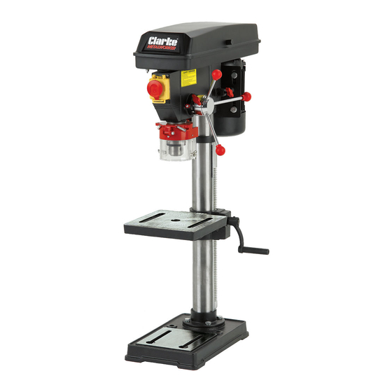
- Page 1 12-SPEED DRILL PRESS MODEL NO: CDP152B PART NO: 6505522 OPERATION & MAINTENANCE INSTRUCTIONS GC1115...
-
Page 2: Environmental Protection
INTRODUCTION Thank you for purchasing this CLARKE Drill Press. Before attempting to use this product, please read this manual thoroughly and follow the instructions carefully. In doing so you will ensure the safety of yourself and that of others around you, and you can look forward to your purchase giving you long and satisfactory service. -
Page 3: General Safety Rules
2. Always keep guards in place and in working order. A guard or other part that is damaged should be properly repaired or replaced by your Clarke service department, unless otherwise indicated in this instruction manual. -
Page 4: Additional Safety Rules For Drill Presses
Check for alignment of moving parts, binding of moving parts, breakage of parts, mounting or other condition that may affect its operation. 7. Have defective switches repaired by your Clarke service department. Do not use a power tool if the switch does not turn it on and off. -
Page 5: Protective Clothing
3. Always use clamps or a drill vice bolted to the table, to hold the work. It should never be held with bare hands. 4. Always shut off the power & remove drill bit before leaving the machine. 5. Always make all adjustments with the power off. 6. -
Page 6: Safety Symbols
SAFETY SYMBOLS The following symbols are shown on the product or it’s packaging. Read instruction CE Mark manual before use Do not wear gloves Falls within Waste Electrical Equipment (WEEE) Directive Wear eye protection Parts & Service: 020 8988 7400 / E-mail: Parts@clarkeinternational.com or Service@clarkeinternational.com... -
Page 7: Electrical Connections
ELECTRICAL CONNECTIONS WARNING! READ THESE ELECTRICAL SAFETY INSTRUCTIONS THOROUGHLY BEFORE CONNECTING THE PRODUCT TO THE MAINS SUPPLY. Before switching the product on, make sure that the voltage of your electricity supply is the same as that indicated on the rating plate. This product is designed to operate on 230VAC 50Hz. -
Page 8: Parts Inventory
PARTS INVENTORY Chuck Guard assembly Base Head assembly Table with worm drive Feed handles (x 3) Chuck with key Hex Keys (3mm/4mm) Column collar Column Crank handle Rack Bolts & washers Parts & Service: 020 8988 7400 / E-mail: Parts@clarkeinternational.com or Service@clarkeinternational.com... -
Page 9: Column To Base
The drill press is delivered with the components shown on page 8. Check the parts against the list. Should there be any deficiencies or damage, you should contact your CLARKE dealer immediately where the product was originally purchased. Do not discard the packaging until the machine is assembled. - Page 10 2. Position the rack in the slot in the table support, so that the rack teeth engage with the worm gear. Position the centre of the rack close to the worm gear as shown in Fig 2, with the long, smooth end uppermost.
-
Page 11: Head To Column
HEAD TO COLUMN NOTE: It may be necessary to unscrew the set-screws (shown in fig.4) to ensure they do not protrude internally and foul the column, as this would prevent the head from sliding fully into position. 1. With the help of an assistant, lift up the head assembly and locate it on the column, ensuring it slides fully home. -
Page 12: Installing The Chuck
INSTALLING THE CHUCK 1. Open the jaws of the chuck as far as possible using the chuck key supplied. Ensure the tapered hole in the chuck is clean and fit the chuck onto the tapered end of the drive spindle with a firm pressure. -
Page 13: Settings And Adjustments
SETTINGS AND ADJUSTMENTS TABLE The table may be raised, lowered or swivelled around the column by slackening the table support locking handle shown in Fig 10, and adjusting the table position accordingly and retightening the locking handle. It may also be tilted by loosening the bolt which secures the table to its mounting, tilting the table to the required position and retightening... -
Page 14: Spindle Depth Stop
SPINDLE DEPTH STOP Located on the spindle feed shaft is a depth stop collar, carrying a graduated scale (A, in Fig.13). The collar can rotate around the shaft and may be locked in place by the locking screw B. The graduations represent the hole depth in mm. -
Page 15: Drill Operating Speeds
4. When the belt has been correctly positioned, re-tension by levering the motor away from the head until the belt deflects by approx 10 mm at its centre when using reasonable thumb pressure. 5. Lock the motor in this position with the belt tension locking knob. DRILL OPERATING SPEEDS The table below gives the belt arrangement for given drilling speeds. -
Page 16: Operation
OPERATION 1. Insert the drill bit into the jaws of the chuck by approx 1". Before tightening the chuck, ensure that the drill bit is centred within the jaws. 2. Ensure the table height and position is set, so that drill travel is sufficient for the job in hand. - Page 17 8. When completely satisfied that the setup is correct, lower the chuck guard into position and switch the machine ON. • Switch on by pushing the ‘I’ button. • To switch OFF, push the ‘O’ button, see Fig 16. 9. During use, the emergency stop button will drop down over the other buttons.
-
Page 18: Drilling Speeds
12.5 Steel DRILL VICES In order to secure the workpiece to the table, a complete range of drill vices, cross vices and clamps is available from your Clarke dealer. Parts & Service: 020 8988 7400 / E-mail: Parts@clarkeinternational.com or Service@clarkeinternational.com... -
Page 19: Maintenance
Always unplug from the power supply before carrying out any adjustment, servicing or maintenance. Please refer to the Troubleshooting chart on page 20. If you are unable to rectify any faults, please contact your local dealer or Clarke International for assistance. MONTHLY (IF IN CONSTANT USE) 1. -
Page 20: Troubleshooting
Close pulley cover. g. Micro switch on cover g. Check operation of micro not operating. switch, and renew/adjust as necessary. (Consult your Clarke dealer for advice). Drill binds in work- a. Excessive feed a. Apply less pressure. piece. pressure. - Page 21 Drill bit burns or a. Incorrect speed. a. Refer to Cutting Speed chart smokes. & adjust drill speed accordingly. b. Swarf is not discharging b. Clean drill. c. Dull drill or not proper c. Check sharpness & taper. clearance for material. d.
-
Page 22: Suitable Accessories
SUITABLE ACCESSORIES Drill Press Vices available from your Clarke dealer include: Model Jaw Width Max Opening Depth Weight Part No CDV30C 76 mm 78 mm 19 mm 2 kg 6504019 CDV40C 102 mm 97 mm 28 mm 3 kg 6504020... -
Page 23: Specification
SPECIFICATION Overall Height 830 mm Table Dimensions 203 x 195 mm Base Dimensions 207 x 338 mm Chuck Capacity 3-16 mm Max Chuck to Table Distance 355 mm Max Chuck to Base Distance 460 mm Spindle Speed Range 300-2250 rpm No of Speeds Spindle Taper Max Spindle Travel... -
Page 24: Component Parts
COMPONENT PARTS Parts & Service: 020 8988 7400 / E-mail: Parts@clarkeinternational.com or Service@clarkeinternational.com... - Page 25 COMPONENT PARTS No Description No Description Base Washer Column Flange Motor Connection Plate Flat Washer Motor Spring Washer Hex Bolt M8x25 Hex Socket Set Screw Hex Bolt M6x12 Motor Pulley Crank Handle Damping Washer Circlip 14mm Worm Flat Washer Worm Pin Spring Washer Worm Gear Pulley Cover...
- Page 26 Plug and Cable Washer Screw M8x15 Circlip 12mm Housing Main Spindle Cross Head Self-tapping screw Chuck Switch Chuck Guard Cross Head screw Hex Wrench Switch Box Hex Wrench Cross Head screw Drive Belt Earth Connection Middle Pulley Tooth Lock Washer Eccentric Shaft Bearing Cross Pan Head Screw...
-
Page 27: Declaration Of Conformity
DECLARATION OF CONFORMITY Parts & Service: 020 8988 7400 / E-mail: Parts@clarkeinternational.com or Service@clarkeinternational.com...
Need help?
Do you have a question about the CDP152B and is the answer not in the manual?
Questions and answers